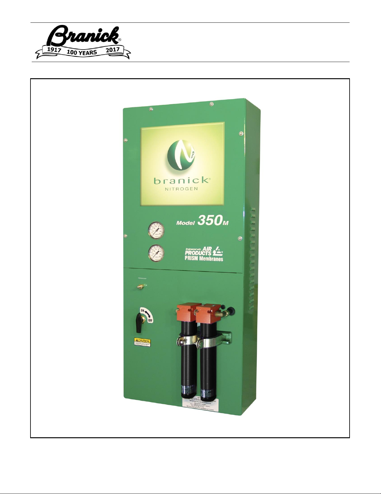
Branick Industries, Inc.
Nitrogen Products
COMMERCIAL WARRANTY
(Non-Transferrable)
This product is warranted by BRANICK INDUSTRIES, INC. to the original user-owner against defective
materials or workmanship. During the warranty period, if Branick determines the product or components
to be defective, it will be repaired or replaced (at Branick’s option).
___________________________________________________________________________________________
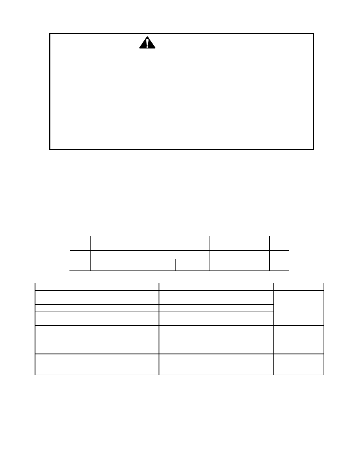
Warranty Period
Labor: 12 months from the date of delivery.
Parts: 12 months from the date of delivery.
Nitrogen Membranes: 60 month warranty from the date of delivery. Proper pre-filter maintenance must
be followed as stated in this manual including changing filters every six (6)
months, and using ONLY filters purchased through Branick. Not doing so will void
the five year warranty. Contamination in the membrane including water, oil,
solvents, particles, and other contaminants will void the warranty. Connecting to
an airline with an oiler, or an unmaintained compressor will void the five
year warranty. In order for a membrane to be considered for warranty
replacement, it must be returned for inspection.
Service or Repair: Warranty service or repairs must be performed by a Branick designated service
company. Membranes replaced under warranty will remain under warranty for
the remaining portion of the original warranty period.
This warranty does not cover damage to the product caused by abuse, misuse, overloading, accident (including
shipping damage), improper maintenance, alteration, or any other cause not the result of defective materials or
workmanship.
Replacement is the exclusive remedy for defective product under this warranty. This warranty is expressly in lieu
of all other warranties, including any implied warranty of merchantability or any implied warranty of fitness for a
particular purpose of this product. Branick industries, inc. Shall not be liable for any consequential or incidental
damages.
BRANICK INDUSTRIES, INC. reserves the right to make changes in the design or construction of our products
without obligation to incorporate such changes in products already sold and without notice.
Service parts, warranty, and regular repair service for Nitrogen products are available Monday through Friday,
7:30am to 4:30pm CST.
BRANICK INDUSTRIES, INC.
4245 Main Ave.
Fargo, North Dakota 58103
1-877-N2-HOTLINE
© Copyright 2018 by Branick Industries, Inc. Printed in U.S.A.