Bras B-cream HD Series User manual

29
This Service Manual is intended solely for internal use by the manufacturer and his technical support team or other simi-
larly qualified persons, in order to prevent any risks.
This manual describes the procedures for adjustment, maintenance and repair of the dispenser. For information regarding
ordinary usage by the operator, please refer to the Instruction Manual provided with each dispenser.
1 APPLIANCE’S DESCRIPTION
This dispenser is designed for the production of iced or frozen drinks such as crushed ice drinks, ice creams and sorbets. The lower
half of the dispenser contains the cooling system, which consists of a compressor (1), a condenser (3), the related fans (2) and a
solenoid valve to open and close the cooling circuit. The lower half of the dispenser also contains the circuit boards designed to
control operation (14) and (16) and the power supply transformer (15) for both the circuit boards and the geared motor to drive the
mixers.
The upper half of the dispenser contains the transparent tank (8) designed for the food product, which in turn contains the mixer (7)
and the evaporator cylinder (5) which is the unit that chills the product. In addition, the rear of the dispenser houses the electric motor
(4) and the geared motor which drives the mixer, the tank defrosting fan (10) and any LED lamps.
figure 1
The dispenser also features a main ON/OFF switch situated on the left-hand side of the frame underside. In addition, each tank is
fitted with a control panel, situated under the dispenser tap, the functions of which are described below.
BCREAM HD 1/2/3
The model BCream HD, in production starting from year 2014, has the following differences from the previous model:
More powerful mixing system
Cup sensor for ease of dispensing
Graphic display showing a larger number of messages
Improved software for better product handling
Timer for operation programming
B-Cream & B-cream HD
30
ENGLISH
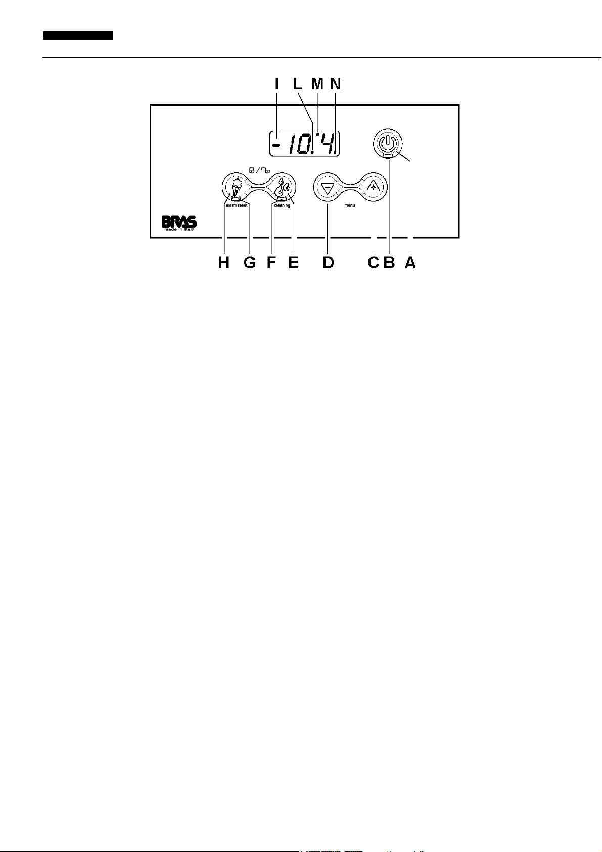
BCREAM 1/2/3
figura 2
(A) ON / OFF key (on dispensers with more than one tank, this key is only present on the right-hand tank control panel): press
it for one second to turn the dispenser on or off. When the appliance is in use, press it briefly to turn the lights on or off, where
featured.
(B) Status indicator light (on dispensers with more than one tank, this indicator light is only present on the right-hand tank control
panel): if it is on, this means the main switch situated under the dispenser is turned on and the appliance is powered and
ready for use.
(C) Plus key: in ice cream production mode, this key increases the density of the product.
(D) Minus key: in ice cream production mode, this key decreases the density of the product.
(E) Conservation key: allows you to select the product conservation operating mode. On dispensers with more than one tank, if
you hold this key down while the tank is in product conservation mode, the corresponding tank will be turned off. If you press
it for two seconds, the dispenser switches to "Cleaning" mode: the mixer is on but the cooling is off.
(F) Conservation indicator light: flashing light => product conservation mode selected, conservation temperature not reached.
Indicator light permanently on => product conservation mode selected, temperature reached.
(G) Ice cream production indicator light: flashing light => ice cream production mode selected, product not ready. Indicator light
permanently on => ice cream production mode selected, product ready.
(H) Ice cream production key: allows you to select the ice cream production operating mode. On dispensers with more than one
tank, if you hold this key down while the tank is in ice cream production mode, the corresponding tank will be turned off.
(I) Product temperature.
(L) Decimal point.
(M) Solenoid valve indicator light: indicator light on => solenoid valve open. Indicator light off => solenoid valve closed. Flashing
indicator light => solenoid valve opening delay under way (factory set to 15 seconds).
(N) Compressor indicator light: indicator light on => compressor on. Indicator light off => compressor off. Flashing indicator light
=> compressor start delay under way (factory set to 120 seconds).
31
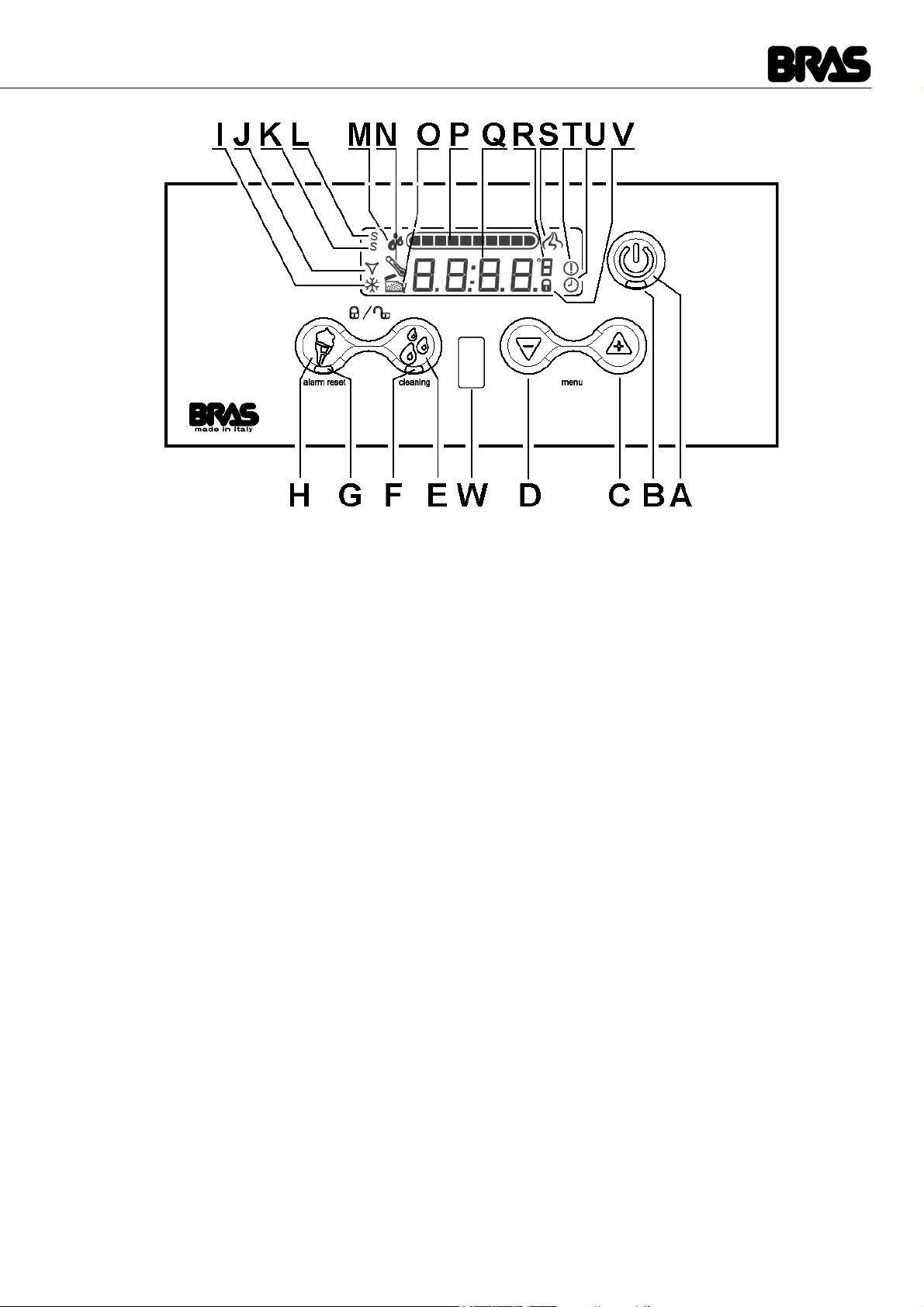
BCREAM HD 1/2/3
figura 3
(A) ON / OFF key (on dispensers with more than one tank, this key is only present on the right-hand tank control panel): press
it for one second to turn the dispenser on or off. When the appliance is in use, press it briefly to turn the lights on or off, where
featured.
(B) Status indicator light (on dispensers with more than one tank, this indicator light is only present on the right-hand tank control
panel): if it is on, this means the main switch situated under the dispenser is turned on and the appliance is powered and
ready for use.
(C) Plus key: in ice cream production mode, this key increases the density of the product.
(D) Minus key: in ice cream production mode, this key decreases the density of the product.
(E) Conservation key: allows you to select the product conservation operating mode. On dispensers with more than one tank, if
you hold this key down while the tank is in product conservation mode, the corresponding tank will be turned off. If you press
it for two seconds, the dispenser switches to "Cleaning" mode: the mixer is on but the cooling is off.
(F) Conservation indicator light: flashing light => product conservation mode selected, conservation temperature not reached.
Indicator light permanently on => product conservation mode selected, temperature reached.
(G) Ice cream production indicator light: flashing light => ice cream production mode selected, product not ready. Indicator light
permanently on => ice cream production mode selected, product ready.
(H) Ice cream production key: allows you to select the ice cream production operating mode. On dispensers with more than one
tank, if you hold this key down while the tank is in ice cream production mode, the corresponding tank will be turned off.
(I) Compressor icon: icon ON => compressor ON. Icon OFF => compressor OFF. Icon blinking => compressor OFF delay in
progress (factory default PA14=180 seconds)
(J) Solenoid valve icon: icon ON => solenoid valve open. Icon OFF => solenoid valve closed . Icon blinking => solenoid valve
closed time in progress (factory default PA15=20 seconds)
(K) Service Mode Icon: icon ON => the machine has been started in Service Mode (main switch + key A) and it is possible to set
the working parameters.
(L) Super Service Mode Icon: this icon and icon (K) ON => the machine has been started in Super Service Mode (main switch
+ key A) and it is possible to set the factory parameters.
(M) Liquid product icon: actualy not implemented
(N) Temperature Alarm Icon: icon ON => the temperature of the product raised over the warning temperature (PA21= 4°C set
as factory default)
(O) Open top cover icon: icon ON => the top cover is open and the machine can’t work (in case of machines with multiple con-
tainers, only the one with the open top cover is stopped).
(P) Viscosity setting: graphical representation of the set value of the viscosity of the product
(Q) Temperature of the product into the bowl
(R) Temperature scale: temperature scale as set by parameter PA08
(S) Dispensing Icon: icon ON => the cup sensor has detected the presence of a cup and the speed of rotation of the mixer is
increased to the value of the parameter PA03
(T) Alarm Icon: icon ON => an alarm is active
B-Cream & B-cream HD
32
ENGLISH
2 OPERATING PRINCIPLE
The operating principle of this dispenser is based on cooling and concurrently mixing the product inside the transparent tank. When
the product reaches negative temperatures, it begins to freeze, thereby increasing in density and therefore the effort required by the
geared motor to mix it. Using the electricity consumption value, the electronic control system is able to determine this effort and when
it reaches a set level, the solenoid valve is closed, thereby shutting off the supply of refrigerant gas to the evaporator cylinder. Since
the product is no longer cooled, it tends to melt, thereby decreasing in density and therefore the effort required by the geared motor
to mix it. When the effort drops below a set level, the solenoid valve re-opens, the refrigerant gas resumes its passage through the
evaporator cylinder and the product cools down and increases in density again. This regulation system ensures the density of the
product is kept at a set level.
Setting the density of the product to between 1 and 10 makes it possible to obtain a product with the required level of density. By
default, the maximum setting, i.e. when the density is set to 10, corresponds to consumption of electrical power of 65 watts, which
can be increased to 100 watts by starting up the machine in Service Mode and adjusting the PA02 parameter (see relative para-
graph). Each density setting value corresponds to 1/10 of the value of the PA02 parameter. In addition to this, the machine checks
that the product temperature does not drop below a minimum operating temperature defined by the PA03 parameter, whose default
setting is -14 °C. This setting is useful to prevent the remaining product gradually reaching ever lower temperatures as the container
is progressively drained.
Again starting up the machine in Service Mode, it is also possible to set the rotation speed of the mixer when the product is being
prepared (PA03 parameter), when the product is ready (PA04 parameter) and when the machine is in product storage mode (PA05
parameter).
As well as the operating modes described in the Instruction Manual, the dispenser may be started up in other modes which can be
used for technical support. These modes are summarised in the table below:
(U) Defrost timer Icon: icon ON => Defrost timer active, the switching between conservation and ice cream mode is operated
automatically following the timer settings and can’t be performed manually.
(V) Locked Keyboard Icon: icon ON => keyboard is locked and it is impossible to adjust the machine unless the keyboard is un-
locked (key E + key H pressed for 2 seconds)
(W) Cup sensor: the cup sensor detects the presence of a cup up to a distance of approx 15 cm and increases the rotation speed
of the mixer to the value of the parameter PA03
IMPORTANT
On dispensers with more than one tank, the ON/OFF key (A) and related indica-
tor light (B) are only present on the control panel of the right-hand tank but their
operation affects the entire appliance. Therefore pressing key (A) will turn all the
tanks on or off and, where featured, it will also turn all the lights on or off.
IMPORTANT
On dispensers with more than one tank, should you wish to turn off a single
tank, you will have to press the key for the operating mode currently in use on
the related control panel. Both the cooling and the mixer will stop and the corre-
sponding display will show the message: OFF.
IMPORTANT
When the ice cream production operating mode is selected, the compressor is
always on. When the dispenser is turned on, after the 120-second safety delay,
the compressor starts up and always stays on.
When the product conservation operating mode is selected, the compressor is
only on if at least one of the solenoid valves is open and therefore if at least one
of the tanks requires cooling. Every time the compressor is turned off, a safety
time lapse of 120 seconds must pass before it can be restarted.
Mode Description Activation key
Operation Parameters Mode In this mode, the machine functions normally but it is pos-
sible to modify the Operation Parameters. Master switch + key A
Production Parameters Mode In this mode, the machine functions normally but it is pos-
sible to modify all Parameters, concerning both Operation
and Production.
Master switch + key A + key H

33
3 SERVICE MODE – ADJUSTING THE OPERATION PARAMETERS
By switching on the dispenser using the master switch and holding down key A simultaneously, the machine can be started up in
service mode and make adjusting the Operation Parameters. The dispenser will function normally, but it will be possible to modify
the operation parameters and any modifications carried out will be stored in the memory for the next time the dispenser is switched
on in normal mode.
When the machine is in use, to adjust the operation parameters, hold down keys C and D simultaneously. The display will show the
code PA01 to indicate the first parameter which may be modified. Pressing keys C and D enables the selection of the parameter to
be modified. Pressing key A will then make it possible to activate the modification of the chosen parameter. The display will show
the current value of the parameter. This value can be modified using keys C and D. Pressing key A once more or waiting three se-
conds without pressing any keys confirms the new value and the display will return to the list of parameters. To exit the parameter
adjustment, hold down keys C and D simultaneously or do not press any key for three seconds.
LIST OF PRODUCTION PARAMETERS B-CREAM 1/2/3
LIST OF PRODUCTION PARAMETERS B-CREAM HD 1/2/3
Test Mode In this mode, the machine does not function and it is possi-
ble to manually activate individual components to check
that they are functioning correctly.
Master switch + key E
Production Test Mode In this mode, the machine does not function and it is possi-
ble to activate individual components in sequence to check
that they are functioning correctly.
Master switch + key H
IMPORTANT
On dispensers with more than one tank, the operating parameters, from PA01 to
PA10, must be set separately for each tank.
NAME DESCRIPTION ADJUSTMENT INTERVAL DEFAULT VALUE
PA01 Minimum temperature in Ice Cream Production Mode: This is the
minimum possible temperature of the product when the density is
adjusted to a value of 10.
0...-18 °C -14
PA02 Maximum density in Ice Cream Production Mode: this is the ab-
sorption value of the motor corresponding to the adjustment of the
density to a value of 10.
0...100 W 60
PA03 Motor rotation speed in Ice Cream Production Mode with an unfi-
nished product. 500…6000 giri/min 3500
PA04 Motor rotation speed in Ice Cream Production Mode with a finished
product. 500…6000 giri/min 3500
PA05 Motor rotation speed in Conservation Mode. 500…6000 giri/min 1000
PA06 Temperature produced in Conservation Mode. - 25 ÷ + 10 °C 2 °C
PA07 Lock Keypad. 0 / 1 / 2 0
PA08 Scale representation of temperature. C…F C
PA09 Firmware version display circuit board. Visualisation only
PA10 Firmware version power circuit board. Visualisation only
NAME DESCRIPTION ADJUSTMENT INTERVAL DEFAULT VALUE
PA01 Minimum temperature in Ice Cream Production Mode: This is the
minimum possible temperature of the product when the density is
adjusted to a value of 10.
0...-18 °C -14
PA02 Maximum density in Ice Cream Production Mode: this is the ab-
sorption value of the motor corresponding to the adjustment of the
density to a value of 10.
45...90 W 75
PA03 Motor rotation speed in Ice Cream Production Mode with an unfi-
nished product. 2000…6000 giri/min 4000
PA04 Motor rotation speed in Ice Cream Production Mode with a finished
product. 2000…6000 giri/min 2000
PA05 Motor rotation speed in Conservation Mode. 1000…6000 giri/min 1000
PA06 Temperature produced in Conservation Mode. - 5 ÷ + 10 °C 2 °C
B-Cream & B-cream HD
34
ENGLISH
4 SUPER SERVICE MODE – ADJUSTING THE MANUFACTORY PARAMETERS
By switching on the dispenser using the master switch and holding down keys A and H simultaneously, the machine can be started
up in Super Service Mode and make adjusting the manufactory parameters. The dispenser will function normally, but it will be pos-
sible to modify the production parameters and any modifications carried out will be stored in the memory for the next time the dispen-
ser is switched on in normal mode.
For information on how to adjust the production parameters, please refer to the instructions for the operation parameters.
LIST OF PRODUCTION PARAMETERS B-CREAM 1/2/3
LIST OF PRODUCTION PARAMETERS B-CREAM HD 1/2/3
PA07 Lock Keypad. 0 / 1 / 2 0
PA08 Scale representation of temperature. C…F C
PA09 Firmware version display circuit board.
2015 version : enabling defrost timer. Visualisation only
ON / OFF OFF
PA10 Firmware version power circuit board.
2015 version : counter machine life Visualisation only
Days 0
IMPORTANT
Incorrect adjustment of the Production Parameters may compromise the opera-
tion of the machine.
IMPORTANT
Distributors in more containers from the factory parameters PA11 to PA 27 are
common to all the distributor and therefore can only be adjusted by the control
panel on the right container.
NAME DESCRIPTION ADJUSTMENT INTERVAL DEFAULT VALUE
PA11 Ice Cream Production Mode Density 1…10 8
PA12 Ice Cream Production Mode Density Hysteresis 0...4,0 0,2
PA13 Ice Cream Production Mode Temperature Hysteresis 0…5 °C 0,5
PA14 Compressor lockout time OFF 0…600 s 180
PA15 Electrovalve lockout time OFF 0…600 s 180
PA16 Time for which the density must remain above the reference value 0…60 s 1
PA17 Conservation Mode Temperature Hysteresis 0…5 °C 0,5
PA18 Maximum motor absorption 0…100 W 90
PA19 Motor cooling time 0…600 s 90
PA20 Motor protection intervention delay 0…60 s 5
PA21 Product conservation alarm temperature 0…10 °C 4
PA22 Tap sensor entry activation ON…OFF OFF
PA23 Temperature probe offset ? 0
PA24 Number of motor poles 0…1000 300
PA25 Motor control proportional P constant 0…1000 4
PA26 Motor control integral I constant 0…1000 0
PA27 Motor control derivative D constant YES…NO NO
NAME DESCRIPTION ADJUSTMENT INTERVAL DEFAULT VALUE
PA11 Ice Cream Production Mode Density 1…10 8
PA12 Ice Cream Production Mode Density Hysteresis 0...4,0 0,2
PA13 Ice Cream Production Mode Temperature Hysteresis 0…5 °C 0,5
PA14 Compressor lockout time OFF 0…600 s 180

35
5 PARAMETER RESET
To reset the parameters to the default values it is necessary to switch on the machine, using the main switch located under the unit,
holding down keys C and D simultaneosly, selecting YES value pressing key C and then confirming it, pressing key A.
It is also possible to reset the parameters to the default values starting the machine in Super Service Mode, selecting parameters
PA27, selecting YES value pressing key C and then confirming it, pressing key A.
6 FUNCTIONAL TEST OF THE MACHINE
The following procedure allows to test the complete functionality of the unit:
1Switch On the machine.
2If in Standby set the machine in Working Mode.
3Set all the bowls in Ice Cream Mode: the gear motors must turn regularly. The icon J flashes on the right display. The icons I
flash on all the displays.
4After 15 seconds, when the time set by parameter PA15 is expired (delay timer of the solenoid valves, factory default 15 sec.)
the solenoid valves open (the sound "click" must be heard one time for each bowl in a short time). The icon J, on all the display,
stop flashing becoming still.
5After 180 seconds, when the time set by parameter PA14 is expired (delay timer of the compressor, factory default 180 sec) the
compressor and the fan motor start. Now the cooling system of the machine is working and after some ten of seconds the
evaporators must begin to freeze in the front lower part. The icon I, on the right display, stops flashing becoming still.
6If it is possible to complete this procedure with success it means that the machine works properly.
This test takes approx. 5 minutes and allows to verify the proper working of the gear motors, of the compressor, of the fan motor, of
the solenoid valves and of the electronic boards all together.
The only thing that this procedure can't allow to verify is the efficiency of the cooling system which can be reduced for example due
to a leak of refrigerant gas. In order to execute such a check, a test with product, 90 minutes long, is required.
7 PROTECTION AGAINST EXCESSIVE DENSITY
In the case of excessive product density, in order to avoid damage to the dispenser, both the freezer and the mixer will be stopped
for three minutes and one of the following messages will appear on the display: “AL03”, “AL06” or “AL08”. After three minutes, both
mixing and freezing will be reactivated and the previous density setting will be decreased by one level.
To reset the alarm message and return to the fixed display, hold down the B key for three seconds.
From serial number 1184, with the introduction of firmware versions 025 and 018, the alarm display has been replaced by the symbol
---- shown on the display.
The alarm display is possible in Service Mode or Super Service (see paragraph 3 and 4) or, during normal operation, by simultane-
ously pressing the + and -.
8 ALARMS
The table below summarises the machine’s alarm codes:
PA15 Electrovalve lockout time OFF 0…600 s 20
PA16 Time for which the density must remain above the reference value 0…60 s 1
PA17 Conservation Mode Temperature Hysteresis 0…5 °C 0,5
PA18 Maximum motor absorption YES…NO 120
PA19 Motor cooling time 0…600 s 90
PA20 Motor protection intervention delay 0…60 s 5
PA21 Product conservation alarm temperature 0…10 °C 4
PA22 Tap sensor entry activation ON / OFF OFF
PA23 Available for future implementations
2015 version : locking density 0...25
YES / NO 0
NO
PA24 Mixer rotation inversion when in conservation mode YES…NO YES
PA25 Mixer rotation inversion delay 0…3600 900
PA26 Minimum time of rotation speed increasing when cup is detected 0…60 10
PA27 Reset of the parameters to default values YES…NO NO
Code Title alarm Note
COV Cover opened It warns the operator that the machine can not operate if the
lid is not closed
AL02 Product temperature alarm This alarm stops the operation of the machine

B-Cream & B-cream HD
36
ENGLISH
If one of these alarm codes appears on the display, please refer to Appendix 1: Possible Problems and their Solutions.
9 FIRMWARE VERSIONS CHRONOLOGY
Control display
Power board
AL03 Excessive motor absorption Alarm displayed when the machine is operating in Service
Mode Service Mode or Super
AL04 Temperature probe damaged This alarm stops the operation of the machine
AL05 Circuit board transmission error This alarm stops the operation of the machine
AL06 Unplanned motor stop Alarm displayed when the machine is operating in Service
Mode Service Mode or Super
AL07 24V power supply missing This alarm stops the operation of the machine
AL08 Excess current, hardware protection intervention Alarm displayed when the machine is operating in Service
Mode Service Mode or Super
AL09 Error Hall probes This alarm stops the operation of the machine
AL10 Lack of communication between master and slave card 1 This alarm stops the operation of the machine
AL11 Lack of communication between master and slave card 2 This alarm stops the operation of the machine
AL12 Alarm low voltage motor This alarm don’t stops the operation of the machine
AL13 System clock out of order System clock out of order. The machine can work but the de-
frost timer can’t be used.
AL14 Clock battery out of order Clock battery expired or out of order. The machine can work
but current time is reset when the machine is powered off.
Version Notes
0.22 First production version.
0.23 Updates 2013.
1.01 Updates 2014.
First produtcion version with LCD display.
1.08 Updates 2015.
Version Notes
0.06 First production version.
0.10 Updates 2013.
0.27 Updates 2014.
Compatible version with new LCD display.
0.35 Updates 2015.
37
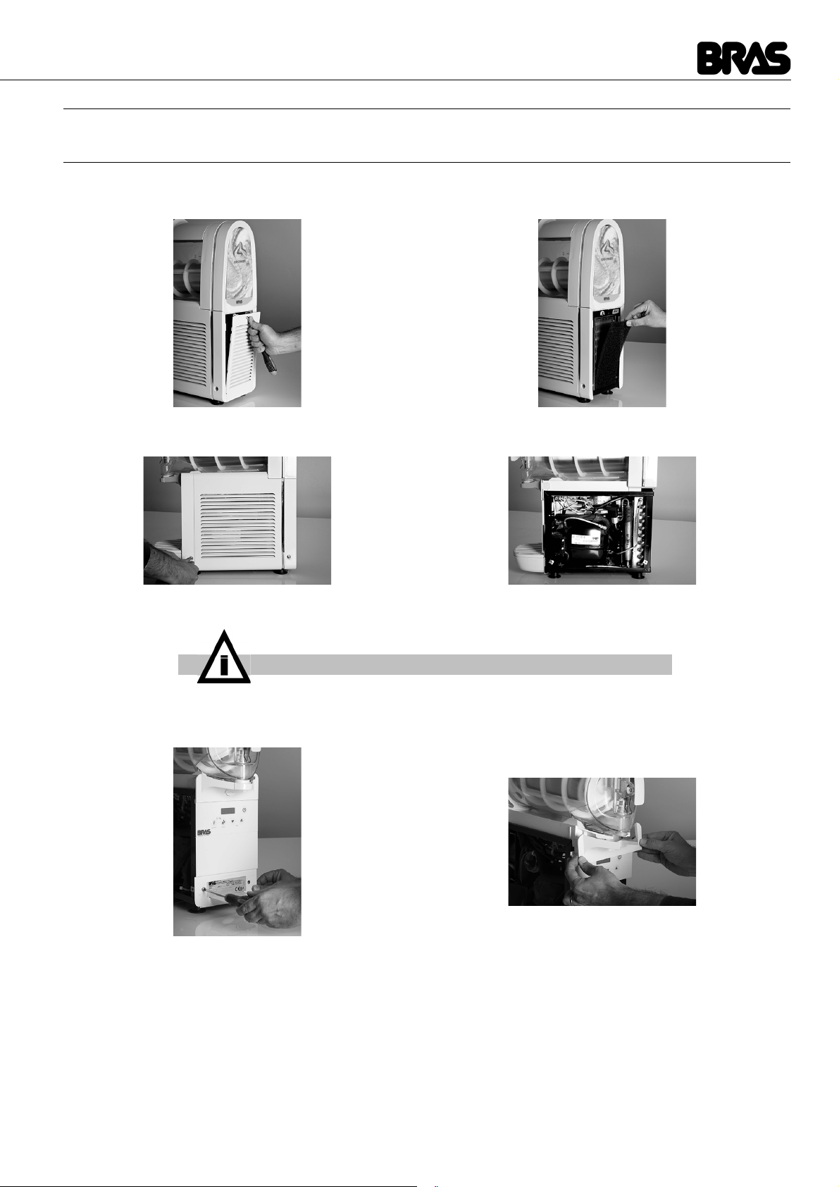
10 DISASSEMBLING THE DISPENSER
10. 1 OPENING THE DISPENSER
1Remove the rear panel, prising it open with a screwdriver inserted in the purpose-designed slot, then remove the condenser
filter.
2Loosen the fastening screws and remove the side panels.
3Loosen the screws and remove the front panel. Then remove the condensation water drain cover.
4Once you have removed the cover, the tank and mixer, loosen the fastening screws on the condensation water collection tray
IMPORTANT
The side panels cannot be removed if the rear panel has not previously been
disassembled.
B-Cream & B-cream HD
38
ENGLISH
and remove it by pulling it out from the front.
10. 2 DISASSEMBLING THE CIRCUIT BOARDS
1Remove the control board housing by pushing it down.
2Disconnect all connectors at the rear of the board. Loosen all the housing securing screws and then remove the board itself.
3To remove the power board, you need to disconnect all the connectors then pull down the two side anchor tabs and pull out the
board.
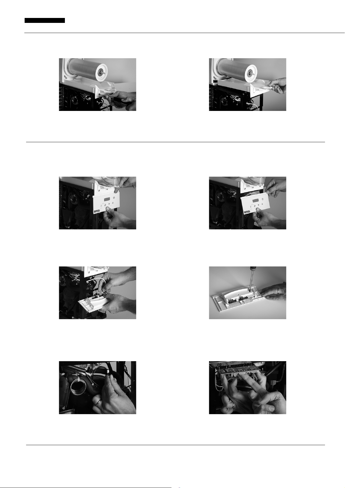
10. 3 DISASSEMBLING THE WATER COLLECTION TRAY
1Remove the advertising picture at the rear by prising it off with a screwdriver inserted in the purpose-provided slot. Loosen the

39
fastening screw and pull the water collection tray out.
10. 4 DISASSEMBLING THE GEARED MOTOR
1Remove the rear cover after loosening its fastening screws.
2Loosen the fastening nuts on the geared motor and remove the latter from its seat.
10. 5 DISASSEMBLING THE DEFROSTING FAN AND THE LID PRESENCE SENSORS
1Remove the air conveyor by pressing on either side. Pull the defrosting fan out of its seat in the conveyor. The lid presence
detectors are situated at the rear of the conveyor and can be removed from their seat with the help of a small screwdriver.
10. 6 DISASSEMBLING THE TEMPERATURE SENSOR
1The temperature sensor is situated inside the front evaporator cylinder cap. To replace it, first loosen the fastening nuts, then,

B-Cream & B-cream HD
40
ENGLISH
with the help of a rubber hammer, push the tie rods and then pull the front cap out.
2Lastly, loosen the temperature sensor fastening screw situated inside the cap. If necessary, pull out the mixer drive shaft from
its seat.
11 UPDATING THE FIRMWARE
The dispenser firmware can be updated by uploading the correct update files to the circuit board memory. Each board, control board,
master power board and slave power board has its own firmware which can be updated individually. To do this, you need the special
programmer supplied by the manufacturer shown in the figure below. This is supplied with an adapter which is used or not according
to the connector on the circuit boards.
In addition to the programmer, the update files supplied by the manufacturer named as shown in the table below are required:
The files must be saved to a Personal Computer (PC) with a USB port.
11. 1 UPDATING THE CONTROL BOARD FIRMWARE
To update the control board firmware, perform the steps described below.
1Collect the programmer to the USB port on the PC where the firmware update files are stored. The programmer will be
recognised by the PC as a normal USB storage device (memory stick). Delete any files on the programmer and copy the file
Brushless_Front_XXX.mot onto it making sure that when you have finished, this is the only file on the programmer.
2While the machine is disconnected from the mains, access the control board following the steps described above without
disconnecting the board from the connectors.
3Connect the programmer to the MC3 connector shown in the figure. Connect the machine to the mains and switch on the
master switch. The green PROGRAMMING light on the programmer will come on to confirm that it is connected to the board
correctly and that the board is powered. Press the programming button on the programmer. The green PROGRAMMING light will
Brushless_Front_XXX.mot
Brushless_M_S_MASTER_vXXX.mot
Brushless_M_S_SLAVE_vXXX.mot
Version XXX front board firmware
Version XXX master power board firmware
Version XXX slave power board firmware

41
flash for a few seconds; when it remains permanently lit, programming has been terminated correctly.
4Switch off the master switch and disconnect the machine from the mains.
5Disconnect the programmer and put the control board back into its housing.
11. 2 UPDATING THE MASTER POWER BOARD FIRMWARE
To update the master power board firmware, perform the steps described below.
1Collect the programmer to the USB port on the PC where the firmware update files are stored. The programmer will be
recognised by the PC as a normal USB storage device (memory stick). Delete any files on the programmer and copy the file
Brushless_M_S_MASTER_vXXX.mot onto it making sure that when you have finished, this is the only file on the programmer.
2While the machine is disconnected from the mains, access the master power board following the steps described above without
disconnecting the board from the connectors.
3Connect the programmer to the MC1 connector shown in the figure. Connect the machine to the mains and switch on the
master switch. The green PROGRAMMING light on the programmer will come on to confirm that it is connected to the board
correctly and that the board is powered. Press the programming button on the programmer. The green PROGRAMMING light will
flash for a few seconds and when it remains permanently lit, programming has been terminated correctly.
4Switch off the master switch and disconnect the machine from the mains.
5Disconnect the programmer.
11. 3 UPDATING THE SLAVE POWER BOARD FIRMWARE
To update the master power board firmware, perform the steps described below.
1Collect the programmer to the USB port on the PC where the firmware update files are stored. The programmer will be
recognised by the PC as a normal USB storage device (memory stick). Delete any files on the programmer and copy the file
Brushless_M_S_SLAVE_vXXX.mot onto it making sure that when you have finished, this is the only file on the programmer.
2While the machine is disconnected from the mains, access the master power board following the steps described above without
disconnecting the board from the connectors.
3Connect the programmer to the MC1 connector shown in the figure. Connect the machine to the mains and switch on the
master switch. The green PROGRAMMING light on the programmer will come on to confirm that it is connected to the board
IMPORTANT
If updating has not been successful, the red ERROR light will come on.
You will have to repeat the entire procedure making sure you do not make any
mistakes.
IMPORTANT
If updating has not been successful, the red ERROR light will come on.
You will have to repeat the entire procedure making sure you do not make any
mistakes.

B-Cream & B-cream HD
42
ENGLISH
correctly and that the board is powered. Press the programming button on the programmer. The green PROGRAMMING light will
flash for a few seconds and when it remains permanently lit, programming has been terminated correctly.
4Switch off the master switch and disconnect the machine from the mains.
5Disconnect the programmer.
12 REFRIGERATOR CIRCUIT MAINTENANCE
12. 1 LOCATING GAS LEAKS
The following is the recommended method for the systematic inspection of the refrigerator circuit when trying to identify the source
of a gas leak.
Where the copper tube is protected by an insulation grip, the leak can be detected from both ends of each individual grip.
figure 4
Referring to figure 3, proceed as follows:
1Begin the inspection at the “High Pressure” zone (discharge) of the compressor. Check around the seals.
2Follow the copper pipes to the condenser and check the sealed connections at the condenser entrance and exit.
3Also check the curves of the pipes on both sides of the condenser.
4Follow the copper pipes to the evaporator, checking around the sealed connections on the dehydrator filter and the
electrovalves.
5Disassemble the geared motors and check the evaporator capillary tube entry and the suction line outlet.
6Check the copper pipes up to the compressor.
IMPORTANT
When using the leak detector, always direct the sensor towards the bottom of
the copper tubes. The refrigerant gas is heavier than air.
A High pressure (discharge)
B Low pressure (suction)
1 Compressor
2 Condenser
3 Fan
4 Filter
5 Evaporator
6 Accumulator
7 Solenoid valve
43
7Inspect the “Low Pressure” zone of the compressor, checking the connections on the suction and inlet pipes.
8Once the leak has been identified, seal it and charge with gas according to the instructions below.
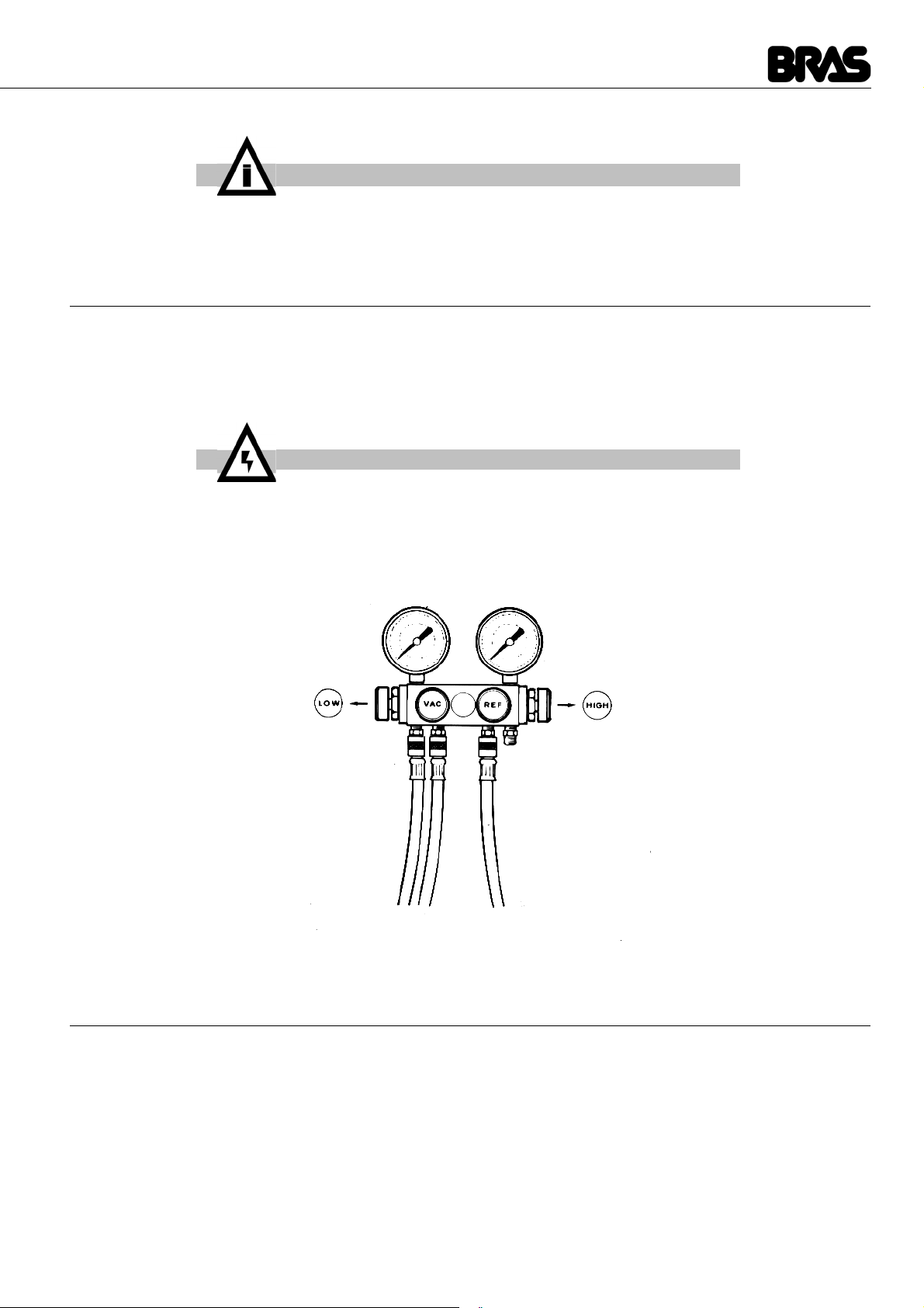
12. 2 HOW TO EMPTY THE CIRCUIT
1Remove all the machine’s panels.
2Remove the cap from the “Charge” pipe valve on the compressor.
3Connect the compressor “Charge” tube to the “Low” filling unit on the “pressure Gauge” (see figure).
4Connect the "VAC” filling unit on the pressure gauge to an appropriate and approved gas collection device.
5Open the “Low” and “VAC” valves and collect the gas.
6Once the discharge operation is complete, close the "Low" and "VAC" valves and disconnect the collection equipment.
figure 5
12. 3 HOW TO EMPTY THE SYSTEM
Before emptying the system, always replace the dehydrator filter with a new one.
1Connect the "REF" filling unit on the pressure gauge to the charging unit.
2Connect the “VAC” filling unit to the vacuum pump and open the “VAC” valve.
3Open the valve on the charging unit and, for a moment, also open the “REF” valve on the pressure gauge, to remove air from
the “REF” pipe.
4In machines with more containers, disconnect the electrovalves from the machine's internal cabling and supply power to them
directly using an auxiliary power supply. This way, the electrovalves are open and the whole circuit is ready to be evacuated.
5Open the “Low” valve on the pressure gauge and run the vacuum pump for approximately thirty minutes.
6While the pump is operating, close the “VAC” valve on the pressure gauge once the preset level of emptying has been reached.
7Switch off the vacuum pump.
8Disconnect the electrovalves from the auxiliary power supply and reconnect the machine's original cabling.
IMPORTANT
Incorrect adjustment of the Production Parameters may compromise the opera-
tion of the machine.
WARNING
The refrigerant gas may be highly acidic and toxic.

B-Cream & B-cream HD
44
ENGLISH
12. 4 HOW TO CHARGE THE MACHINE WITH GAS
The “pressure gauge” shown in figure 5 is the type with 4 filling units (and 4 valves) because this type is most widely available on the
market, and it allows charging with gas both through the “High” and “Low Pressure” zones of the refrigerator circuit.
The refrigerator circuit on our machines is built so that the charging of gas may only be carried out through the compressor charging
tube ("Low Pressure" area): for this reason, the “HI” filling unit is not mentioned or used in our procedures and the “HI” valve should
therefore remain closed at all times.
1Verify how many grams of gas should be decanted. This data, along with the type of gas, is indicated on the machine's
information plate.
2Remove any containers and mixers from the machine.
3Connect the machine’s plug to a power supply and switch the master switch to the "I" position.
4Switch all the “Mixer and Refrigeration” switches to the “I” position and wait until all electrovalves are open (only in multiple
machines) and the compressor starts up.
5Open the valve on the charging unit.
6Open the “REF” valve on the pressure gauge slowly and gently, so that the refrigerant is pushed into the circuit in gas form.
7When the quantity of gas indicated on the Information Plate has been decanted, the refrigerator circuit is charged. Close the
“REF” valve and the valve on the charging unit, keeping the compressor running for a further few minutes.
8Make sure that all the evaporator cylinders are covered with frost.
9Close the “LOW” valve, disconnect the “LOW” pipe from the compressor charging pipe and screw the cap onto the bottom of the
charging pipe.
As an indication, the temperatures and corresponding evaporation and condensation pressures at which the machines must operate
are indicated below.
These temperatures and pressures must be verified under the following operating conditions:
Ambient temperature: 32 °C
Temperature produced in the tank: 0 °C
In these conditions, the evaporation temperature should be approximately -10 °C and the condensation temperature approximately
50°C.
These temperatures should correspond with the temperatures indicated in the table below, depending on the refrigerant gas used:
13 COMPRESSOR FAULTS
To establish if a malfunction has occurred, proceed as follows:
1Disconnect the machine’s plug from the power supply.
2Disconnect the conductors from the compressor terminals.
3Using an ohmmeter, measure the isolation between the terminals and the compressor housing. If the instrument indicates
continuity, the compressor has short-circuited.
4In this situation, the compressor must be replaced using the following method:
5Collect the gas as described in the paragraph "Discharging the gas".
6Remove the faulty compressor.
7Eliminate the cause of the compressor fault (check the conditions of the condenser both when the machine is started up and
when it is operating, and also the condition of the starter relay as possible sources and causes of the fault).
8Install a new compressor and a new dehydrator filter.
9Empty and charge the circuit as described above.
Refrigerant gas Evaporation Pressure Condensation Pressure
R134a 1,00 bar 12,00 bar
R404a 3,20 bar 22,00 bar
45
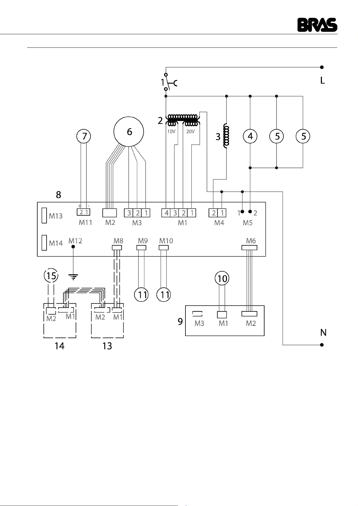
14 WIRING DIAGRAM (1 BOWL)
KEY
1Master Switch 8Power supply circuit board
2Transformer 9Display circuit board
3Electrovalve 10 Temperature probe
4Compressor 11 Reed safety switches
5Fan 13 LED board hat (optional)
6Geared motor 14 LED Board cop. shoulder (optional)
7Defrost fan 15 LED Strip cop. shoulder (optional)
B-Cream & B-cream HD
46
ENGLISH
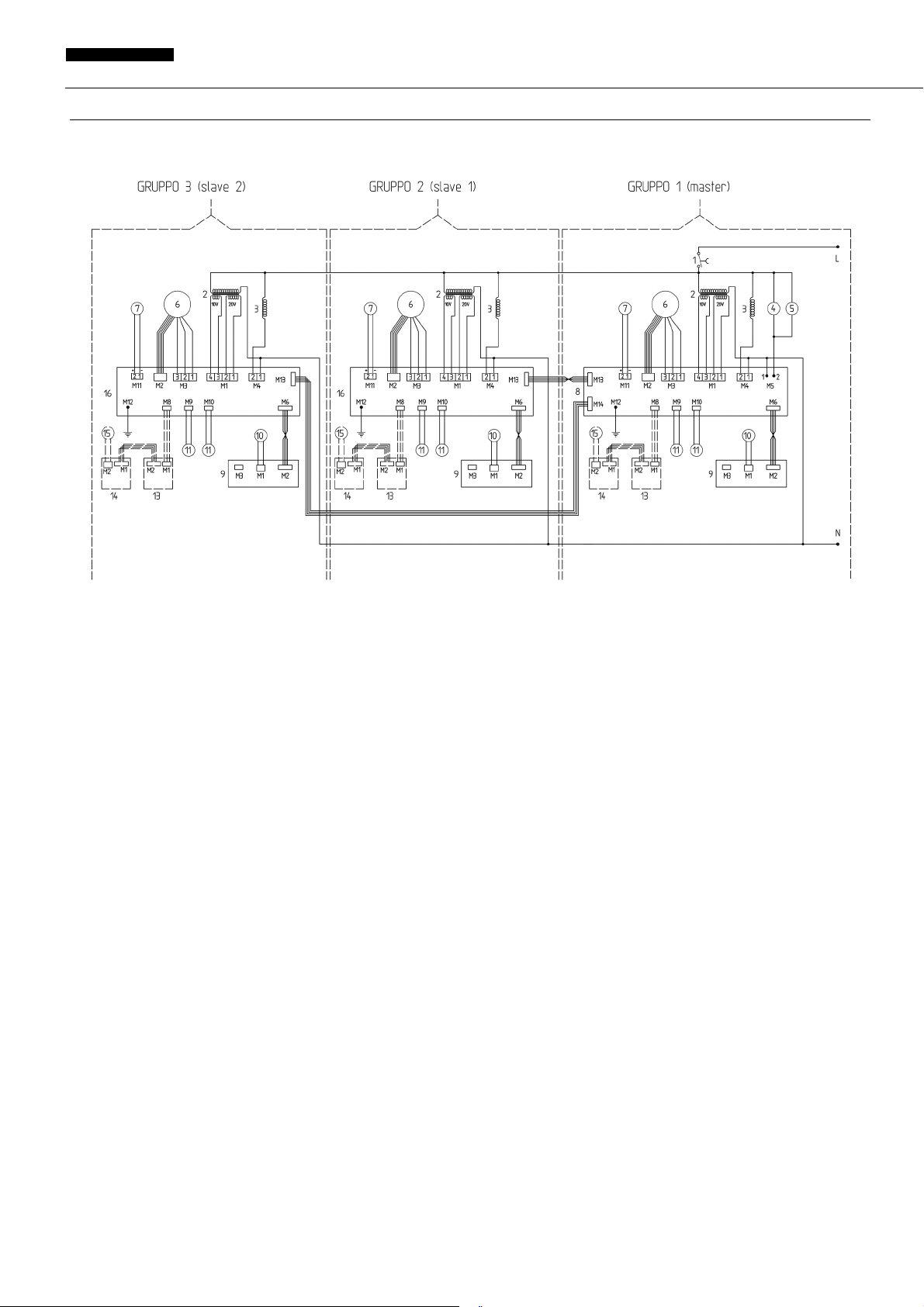
15 WIRING DIAGRAM (2 / 3 BOWLS)
KEY
1Master Switch 9Display circuit board
2Transformer 10 Temperature probe
3Electrovalve 11 Reed safety switches
4Compressor 13 LED board hat (optional)
5Fan 14 LED Board cop. shoulder (optional)
6Geared motor 15 LED Strip cop. shoulder (optional)
7Defrost fan 16 Slave power supply circuit board
8Master power supply circuit board
47
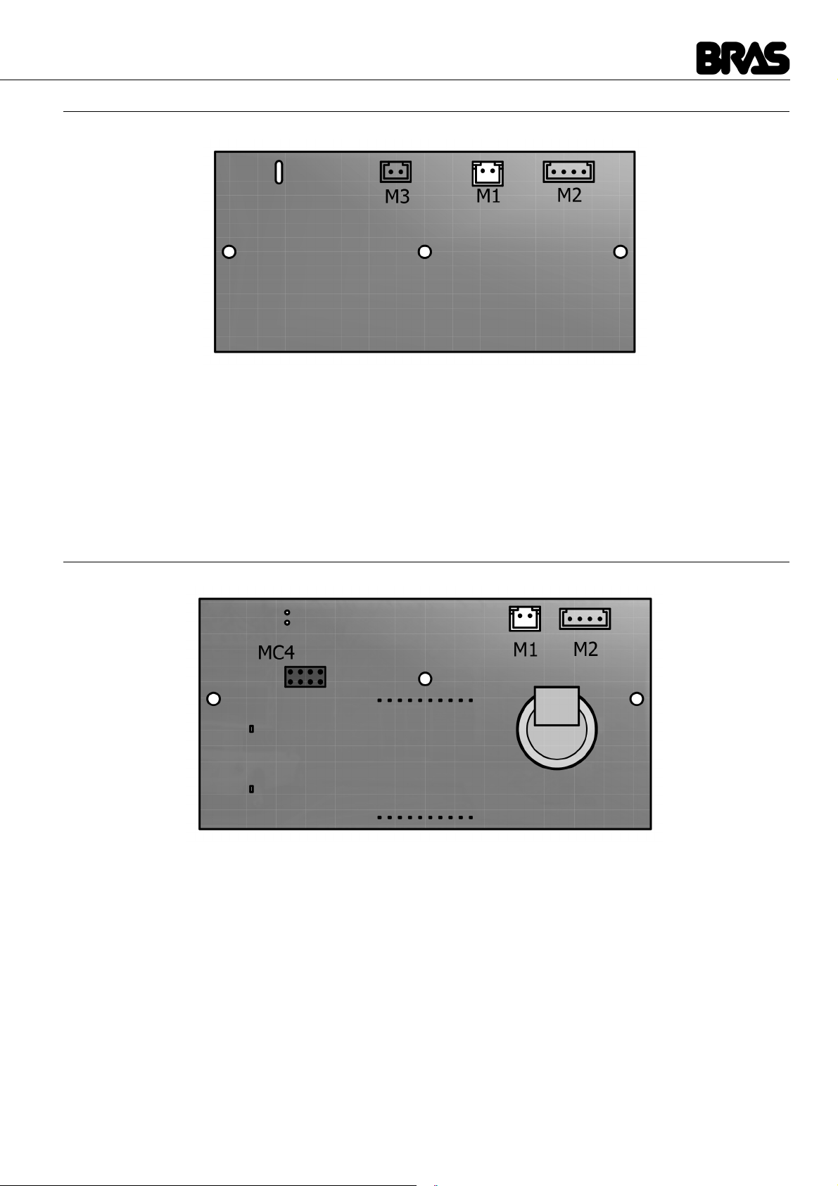
16 TOPOGRAFIC DIAGRAM POWER SUPPLY (DISPLAY MINIGEL)
17 TOPOGRAFIC DIAGRAM POWER SUPPLY (DISPLAY MINIGEL PLUS)
KEY
M1 Temperature probe
M2 MASTER board
M3 Faucet Reed switch (opt)
KEY
M1 Temperature probe
M2 MASTER board
MC4 Programming
B-Cream & B-cream HD
48
ENGLISH
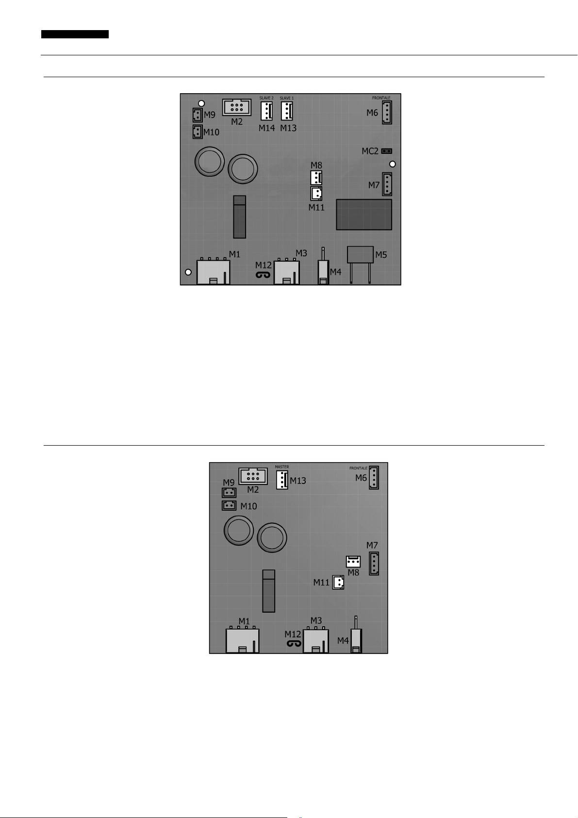
18 TOPOGRAFIC DIAGRAM POWER BOARD (MASTER MINIGEL PLUS)
19 TOPOGRAFIC DIAGRAM POWER BOARD (SLAVE MINIGEL PLUS)
KEY
M1 Power supply 20 Vac pin1-2 / 10 Vac pin 3-4 M9 Safety Reed switch 1
M2 Gearmotor Hall probe signals M10 Safety Reed switch 2
M3 Gearmotor power supply M11 Defrost fan
M4 Solenoid valve M12 Earthing
M5 Compressor M13 Slave 1 board
M6 Display board M14 Slave 2 board
M7 Not connected M15 Closed : machine without solenoid valve
M8 Top cover LED board M16 Open : machine with solenoid valve
KEY
M1 Power supply 20 Vac pin1-2 / 10 Vac pin 3-4 M8 Top cover LED board
M2 Gearmotor Hall probe signals M9 Safety Reed switch 1
M3 Gearmotor power supply M10 Safety Reed switch 2
M4 Solenoid valve M11 Defrost fan
M6 Display board M12 Earthing
M7 Not connected M13 Master board
This manual suits for next models
7
Table of contents
Other Bras Ice Cream Maker manuals


Popular Ice Cream Maker manuals by other brands


Aroma
Aroma AIC-305EM Instruction manual & recipe guide

Hamilton Beach
Hamilton Beach 68320 - Gel Ice Cream Maker Use & care guide

Vollrath
Vollrath Stoelting F212 Operator's manual

Sunbeam
Sunbeam SNOWY GL5400 Instruction booklet

Westfalia
Westfalia ESM 41107 operating instructions

Linea 2000
Linea 2000 DOMO DO9243I Instruction booklet


