Braun Millennium 06 Series Supplement

See inside cover
for warranty and
registration information.
For ADA COMPLIANCE
For ADA COMPLIANCE
TM
Braun Millennium Series
•L915IB
•L915FIB
•L916IB
•L916FIB
•L917IB
•L917FIB
•L918IB
•L918FIB
•L919IB
•L919FIB
Braun Millennium Series 06 Wheelchair Lifts
TM
Series 06
and
L915 Series Lift Models
Special Order
•L915
•L915F
•L916
•L916F
•L917
•L917F
•L918
•L918F
•L919
•L919F
Including Models:
Commercial
Wheelchair Lifts
Installation/Service Manual for:
Americans With
Disabilities Act
Americans With
Disabilities Act
ADA
complying with
complying with ADA
W
ARNING
Read manual
before installing
or servicing lift.
Failuretodoso
may result in
serious bodily
injury and/or
property damage.
ual
M
an
"Providing Access to the World"
International Corporate Hdqrs: P.O. Box 310 Winamac, IN 46996 USA
1-800-THE LIFT (574) 946-6153 FAX: (574) 946-4670
®
®
Patent #5,261,779
Patent #5,806,632
Patent #5,261,779
Patent #5,806,632
25522-06
July 2002
Patent #6,065,924
Patent #6,238,169
Patents Pending
Patent #6,065,924
Patent #6,238,169
Patents Pending

Page 1Supplement 29376
Series A6 andInstallationSupplement 29376
Series A6 &InstallationSupplement 29376
BraunCorporationProductBulletin
Published: January 2003
Subject: Supplement 29376 addresses various lift
installation updates as well as Series A6 technical
information. Further details are outlined below.
The Braun Serial No./Series No. Identification Tag is
posted on the opposite pump side tower. Note the
lift model number and the series number.
If you have a Series A6 or later lift model, read this
supplement as well as all information contained
in L915 Millennium Series™ 06 Installation/Service
manual 25522-06 (and additional supplements),
before installing the lift, servicing the lift or ordering
replacement parts.
Lift Installation Updates:
Lift Ground: Two ground cables are provided with
each lift. One ground cable is pump mounted
(standard - no change). An additional external
battery-to-frame ground cable is now supplied
(effective September 2002). Both cables must be
mounted to a common vehicle framing member to
provide optimum ground. Details are provided in
this supplement.
Compact Circuit Sentry: Effective September
2002, compact Circuit Sentry Kit 28910KS is
supplied with 12 volt lift models to provide greater
installation versatility (less space required). Two
types of mounting brackets are supplied (a flush
mount bracket and an offset mount bracket).
Choose the mounting bracket most suitable for your
application (installation details are provided).
Lift Installation Package: The Installation Parts
List appearing on page 8 of this manual does not
address the additional ground cable, the compact
Circuit Sentry or the associated small parts. These
and other installation parts list changes are ad-
dressed in this supplement.
Service:
Series A6 (Up Solenoid): Series A6 (and later) lift
models are equipped with Prestolite Up solenoid
28308 (effective April 2002). Refer to this supple-
ment for Series A6 technical information. An
electrical schematic, a wiring diagram and pump
module exploded views (with part numbers)
applicable for Series A6 are provided.
Platform Side Plate Modification: Effective
September 2002, the right (front) side plate of 30"
wide platforms was modified (L915, L916, L925
and L926 lift models). This modification is not
depicted in the Lift Terminology Illustration on page
2 of this manual or addressed in the Repair Parts
section. The modified platform and associated
components are addressed in this supplement.
Contact The Braun Corporation at 1-800-THE LIFT
if you have any questions regarding this bulletin.
All illustrations, descriptions and specifications
in this supplement are based on the latest
product information available at the time of
publication. The Braun Corporation reserves
the right to make changes at any time without
notice.
Series A6 andInstallationSupplement Contents
Lift Installation
Installation Parts ..................................................................................................................................... 2
Lift Ground .......................................................................................................................................... 2, 3
Compact Circuit Sentry ....................................................................................................................... 4, 5
Troubleshooting
Series A6 Electrical Schematic ................................................................................................................ 6
Series A6 Wiring Diagram ....................................................................................................................... 7
Repair Parts
Series A6 Rear Pump Module ............................................................................................................. 8, 9
Series A6 Front Pump Module ......................................................................................................... 10, 11
Platform Side Plate Modification ............................................................................................................12

Page 2 Supplement 29376
Series A6 andInstallationSupplement 29376
Series A6 &InstallationSupplement 29376
Installation Parts
Lift Installation Package: The Installation Parts
List appearing on page 8 of this manual does not
address the additional ground cable, the compact
Circuit Sentry or the associated small parts. Refer
to the updates below regarding these changes and
other unrelated part number corrections.
Installation Parts (reference manual page 8)
Part Number Updates
Item 1: The current part number for the underfloor
reinforcement brackets is 25915-04.
Item 4: Two 3/8-16 x 1" hex bolts are now supplied.
The second bolt is supplied for installation of the
battery-to-frame ground cable (if applicable).
Item 17: Two 13/32" I.D. x 1/2" spacers are now
supplied. The second spacer is supplied for installa-
tion of the battery-to-frame ground cable (if appli-
cable).
Item 18: Compact Circuit Sentry Kit 28910KS is
supplied with 12 volt lift models (in Parts Package
25853A-A4). Circuit Sentry assembly 18190A is
being supplied with 24 volt lifts (in Parts Package
26155A-A4).
Item 19: The 1/8" x 4" x 4" flat plastic insulator is no
longer supplied in Parts Package 25853A-A4. The
plastic insulator is not used with Compact Circuit
Sentry Kit 28910KS.
Item 25: The current part number for the Lift
Operating Instructions decal is 27204.
Item 27: The current part number for the Lift
Operation video is 28332.
Item 28: The current part number of the Lift Installa-
tion/Service manual is 25522-06.
Additional (Nonlisted) Parts
Battery-to-frame ground cable 22166A is supplied
with all lifts (12 volt and 24 volt).
Two 5/16-18 x 3/4" thread cutting screws (part
number 21735) are supplied for mounting both
ground cables to the frame (one per cable).
Two 5/16" external tooth star washers (part number
16368) are supplied for mounting both ground
cables to the frame (one per cable).
Lift Ground
Power Cable and Ground Cable Installation
(reference page 17)
Two ground cables are provided with each lift. One
ground cable is pump mounted (standard - no
change). An additional external battery-to-frame
ground cable is now supplied. Both cables must be
mounted to a common vehicle framing member to
provide optimum ground. Refer to following details
and Figure 1.
Note: When mounting ground cables, remove
undercoating, dirt, rust, etc. from the framing
member around the mounting holes (minimum 5/8"
diameter area). Apply a protective coating of
grease to mounting holes to prevent corrosion.
Apply grease to ground cable terminals and
mounting screws also. Failure to do so will void
warranty of certain electrical components.

Page 3Supplement 29376
Series A6 andInstallationSupplement 29376
Series A6 &InstallationSupplement 29376
DOOR OPENING
Lift Base Plate
NEG.
POS.
Pump
Module
Battery
Chassis
Pump Mounted Ground Cable:
Route the pump ground cable through the plastic
floor grommet (shown in Figure 1 and the photo on
manual page 17). Position and secure the ground
cable clear of lift operation. Secure the cable to a
main vehicle framing member. Drill a 9/32" diameter
pilot hole in the frame. Mount the cable using a 5/16-
18 x 3/4" thread cutting screw. Position a 5/16"
external tooth star washer between the cable eye
terminal and the frame. Prepare the cable mounting
surface and apply grease to frame and hardware as
previously detailed (see Note on page 2).
Power Cable
Route, secure and connect the power cable as
detailed on pages 17 and 18 of this manual.
Vehicle Battery Ground Cable:
The external battery-to-frame ground cable supplied
with the lift must be connected to the same vehicle
framing member that the pump ground cable is
attached to. Connect the cable to the negative (-)
battery post. Note: A 3/8-16 x 1" bolt and a 13/32"
I.D. x 1/2" tubing spacer are provided for side
terminal mount batteries.
Secure the opposite end of the cable to the vehicle
framing member. Drill a 9/32" diameter pilot hole in
the frame. Mount the cable using a 5/16-18 x 3/4"
thread cutting screw. Position a 5/16" external tooth
star washer between the cable eye terminal and the
frame. Prepare the cable mounting surface and
apply grease to frame and hardware as previously
detailed (see Note on page 2).
Pump-Mounted Ground Cable
Battery-to-Frame
Ground Cable
Grommet
5/16-18 x 3/4"
Thread Cutting
Screw
5/16"
External
Tooth
Star
Washer
Connect battery-to-frame ground
cable to negative (-) battery post.
Figure 1
Lift Ground (continued)
Power Cable and Ground Cable Installation
(reference page 17)
5/16" External
Tooth Star Washer
5/16-18 x 3/4"
Thread Cutting Screw
Note: The pump
ground cable and
battery-to-frame
ground cable must
be mounted to a
common vehicle
framing member to
provide optimum
ground.

Page 4Supplement 29376
Series A6 andInstallationSupplement 29376
Series A6 &InstallationSupplement 29376
Item Qty. Description Part No.
1 1 Bracket, Flush Mount (Dodge) 28755
2 1 Bracket, Offset Mount (Ford/Chevy) 28498
3 1 Circuit Breaker, 100 Amp. 28704
4 4 Screw, 1/4-14 x 1", Self Drilling, Hex 14145
5 4 Screw, #8-18 x 3/4", Self Drilling, Wafer. Hd. 18790
6 1 Decal, 100 Amp. Circuit Sentry 18181
Compact Circuit Sentry Kit 28910KS
Compact Circuit Sentry
Circuit Sentry Installation and Power Connection (reference page 19)
Bat.
Flush
Mount
Offset
OR
Aux.
Lead Cable to Side Post Mount
Lead Cable
Lift Power Cable
Buss 184100F-03-1
42VDC
3000A INTERRUPT
100A H45
WATERTIGHTENCLOSURE
Side
Post
Mount
Top Post
Mount
Positive (+)
12 Volt
Battery
Post
Lead Cable to Top Post Mount
Flush Mount
Bracket 28755
Offset Mount Bracket 28498
Note: Photos of the compact
Circuit Sentry installed in
Dodge and Ford vans appear
in Service Bulletin 28911
(supplied with each Compact
Circuit Sentry Kit 28910KS).
Circuit Breaker
4
5
Figure 2
Note: Compact Circuit Sentry
Kit 28910KS is supplied with 12
volt lift models only (in Parts
Package 25853A-A4). Circuit
Sentry assembly 18190A is
supplied with 24 volt lifts (in
Parts Package 26155A-A4).
Install 24 volt Circuit Sentry
assembly 18190A as detailed
on page 19 of this manual.
3/8-16 x 1"
Hex Bolt Spacer

Page 5Supplement 29376
Series A6 andInstallationSupplement 29376
Series A6 &InstallationSupplement 29376
1/4-14 x 1" Washer Hex Head Self-Drilling Screws
Flush Mount
Bracket 28755
100 Amp. Circuit
Breaker 28704
A
Circuit Sentry Kit 28910KS is
supplied to provide greater
installation versatility (less space
required). Two types of mount-
ing brackets are supplied (shown
in Figure 2). Bracket 28755 is a
flush mount bracket (without
offset). Bracket 28498 is an
offset mount bracket. Either
bracket can be used as desired.
Select an appropriate mounting
surface in the engine compart-
ment or vehicle battery location.
Select the appropriate mounting
bracket based on the available
mounting surface and other
variables. Mounting brackets can
be oriented as needed.
The Circuit Sentry must be
positioned such that the lead
cable will reach the vehicle
battery. Locate the Circuit Sentry
within 24" of the positive (+)
battery terminal.
Note: Photos of the compact
Circuit Sentry installed in Dodge
and Ford vans appear in Service
Bulletin 28911 (supplied with
each Compact Circuit Sentry Kit).
Mount Circuit Breaker
Mount the circuit breaker to the
mounting bracket. See Figure B
and Photo A. Four .191" diameter
holes spaced 1" apart are pro-
vided in each mounting bracket.
The holes match the pattern of
circuit breaker mounting holes.
Place the bracket securely in a
vice gripping the edge that does
not obstruct positioning of the
circuit breaker (see Photo A).
Mount the breaker to the bracket
using two 1/4-14 x 1" washer hex
head self-drilling screws.
#8-18 x 3/4" wafer head self-
drilling screws are supplied to
mount the circuit breaker and
mounting bracket assembly.
Note: Optional (OEM) mounting
hardware can be utilized in some
applications. Mount the bracket
as needed.
Check for obstructions such as
fuel lines, coolant lines, wires,
exhaust, etc. before drilling.
Cable Connections
Remove the rubber caps
attached to the circuit breaker
terminals. Attach the lift power
cable to the Auxiliary terminal
of the Circuit Sentry. Attach one
end of the battery lead cable to
the Circuit Sentry Battery
terminal. Tighten securely.
Reposition the rubber caps onto
the breaker terminals to prevent
electrical short circuits. Care-
fully connect the opposite end
of the battery lead cable to the
Positive (+) post of the battery.
Decal 18181
Post decal 18181 adjacent to
the Circuit Sentry assembly
(provides circuit breaker reset
instructions).
Note: Clean the surface with
isopropyl alcohol before decal
application. Use a clean cloth
or paper towels. DO NOT use
oily shop rags. Wipe surface
free of residue with dry portion
of cleaning cloth.
Compact Circuit Sentry
Circuit Sentry Installation and Power Connection (reference page 19)
W
ARNING
Risk of electrical
shock! Use extra
care when making
electrical connec-
tions.

Page 6 Supplement 29376
Series A6 andInstallationSupplement 29376
Series A6 &InstallationSupplement 29376
8
7
6
2
1
4
3
5
9
8
7
6
2
1
4
3
5
9
J1 P1
INTERLOCK
PUMP HOUSING
R(6)B(2)
BU
R (16)
R (16)
R (16)
R (16)
BU
GN
BK
BK
YY
BK
BU
BK
W
W
Y
BN
W
GY
BN
BN
GN
GY
R
R (16)
GY
PK
Y
Y (16)
Y (16)
BK (16)
BK (16)
W (16)
W (16)
BN (16)
GN (16)
BK
Y
Y
GN
W/BK (16)
UNFOLD SOLENOID
UP/FOLD
SOLENOID
BRIDGE
SOLENOID
BRIDGE
RELAY
PRESSURE
SWITCH
R(2)
PUMP
R (14)
R
R
100 AMP
CIRCUIT
SENTRY
5 amp
CIRCUIT
BREAKER
R(2) R(2)
R(16)
R(16)
UNFOLD
FOLD
UP
DN
SWITCH BOX
W (16)
BK (16)
BN (16)
Y (16)
GN (16)
GN (16)
LIFT
HYDRAULIC
(UP)
M
GROUND
BAT.
AUX.
12 V.
BATTERY
GY
BK (16) BK (16)
R
R
DOWN
SOLENOID
M
BATTERY
CHASSIS GROUND
CIRCUIT BREAKER
CONNECTORS
JUNCTION
MOTOR
MICROSWITCH
PRESSURE SWITCH
RELAY
SWITCH
SOLENOID
SYMBOLDESCRIPTION
SOLENOID
NC
NO
C
NOTE: ALL WIRES 20 GA. UNLESS
OTHERWISE NOTED.
85 86
30 87
87A
R
R
R
PK
85 86
30 87
87A
BU
BU
BK
BK
W
BU (16)
BN
GY
BK (16)
BU (16)
BN
BK
BU
MICROSWITCH
STATION
UP / FOLD
MICROSWITCH
NC
NO
C
BRIDGE
MICROSWITCH
NC
BU
W (16)
NO
C
GY
W
Y
UNFOLD / DOWN
MICROSWITCH
NC
NO
C
Y
Y
Series A6 LiftElectrical Schematic
Note:Shownwith lift in stowed position.

Page 7Supplement 29376
Series A6 andInstallationSupplement 29376
Series A6 &InstallationSupplement 29376
BK
Y
GN
PIN #1
W/BK
GN
GN
BK
BK
BU
BK
BK
BK
W
GY
GY
Bridge
Down
Unfold
BK
BU
W
R
R
R
R
R
R
R
R
R
Y
Y
GY
PK
PK
PK
Y
Y
R
Pump Ground
R
Interlock
Jumper
Ground
Fold/Unfold
Switch
S
Unfold / Down
Microswitch
Pump Mounted
Platform Sensor
Pressure Switch
C-H
COM
NO
NC
N.O.
N.C.
COM.
S
Up / Fold
Microswitch
C-H
COM
NO
NC
N.O.
N.C.
COM.
PIN #2
BU BU
GY
GY
Y
Y
GY
GY
GY
GN
BK
WBN
Up/Down
Switch
BU
W
W
Y
GY
GY
Y
Y
BU
W
BU
GY
BU
BK
BN
Note: Shown with lift in stowed position.
NOT USED
GREEN - 6 COND.
WHITE - 6 COND.
BROWN - 6 COND.
YELLOW - 6 COND.
BLACK - 6 COND.
NOT USED
NOT USED
NOT USED
6
5
4
3
2
1
COLORNO.
9-COND WIRE CODE
7
8
9
NOT USED
GREEN
WHITE
BROWN
YELLOW
BLACK
NOT USED
NOT USED
NOT USED
6
5
4
3
2
1
COLORNO.
9-COND WIRE CODE
7
8
9
Bridge
Microswitch
Pump
Mounting
Plate
Switch Box
(As Viewed From Terminal
Side of Switch)
123
456
789
321
654
987
N.O.
N.C.
COM.
(Side view of solenoids
removed from pump.)
Bridge
Relay
COM
NO
NC
Hydraulic
Pump
Bridge
Down
Unfold
100 Amp
Circuit Sentry
Bat.
Aux.
Lift
Power Cable
Pump Module
Power Feed
Connects to
Vehicle Battery
(+) Positive Post
#13362A
Lead Wire
BU
or
Note polarity of diode. It
must be oriented as shown.
Detail at left shows two different
styles of diode identification.
R
R
R
R
Up/Fold
Solenoid
Motor Power Feed Wire
Circuit
Breaker
(5 Amp)
B
A
T
A
U
X
Series A6 LiftWiring Diagram
Note:Shownwith lift in stowed position.

Page 8 Supplement 29376
Series A6 andInstallationSupplement 29376
Series A6 &InstallationSupplement 29376
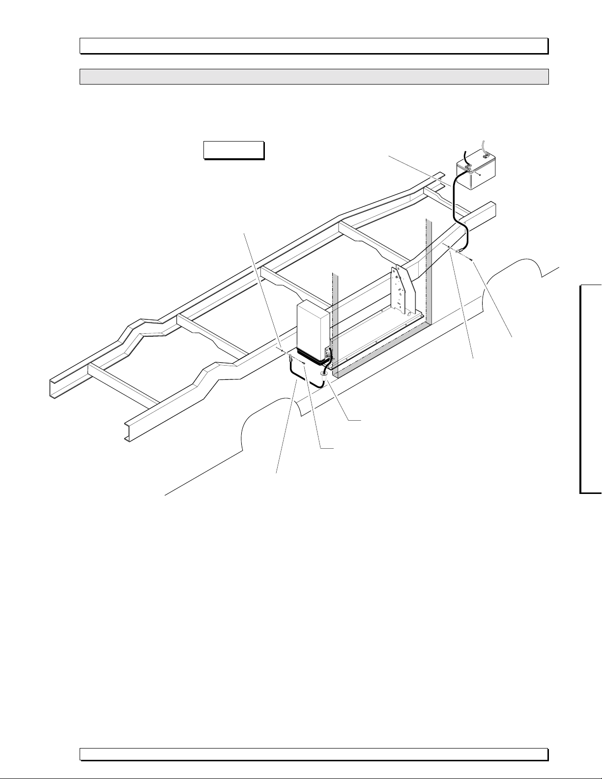
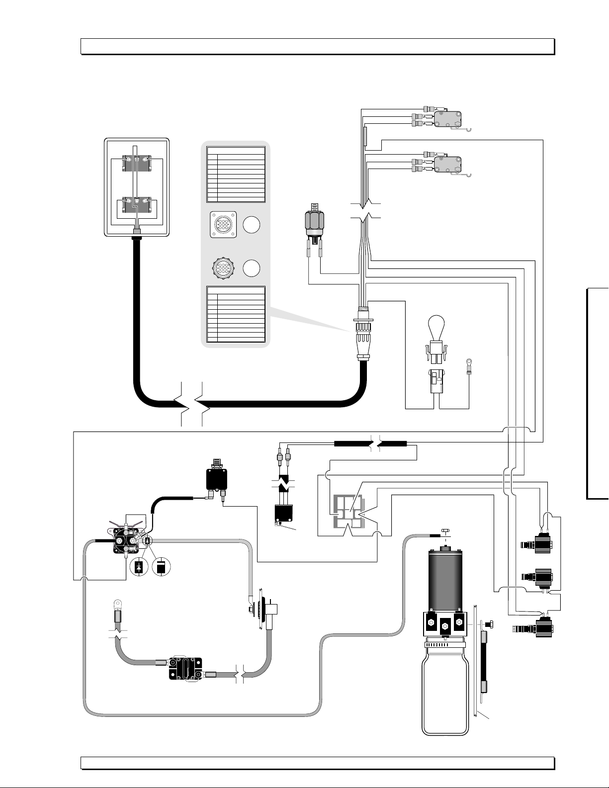
Series A6 Rear Pump Module Parts List
Item Qty. Description Part No. Part No.
1 Pump Module (complete), 12 Volt, Rear 915R6516IBQD 915R6516IBQD
1 1 Pump Assembly (M268 with Reservoir/with Backup pump) Bridge, Prestolite 25597A12V-A6 25597A12V-A6
2 2 Fitting, 7/16”-20 O-Ring Male / 7/16”-20 JIC 37°Male 24504 24504
3 1 Elbow, 7/16”-20 JIC 37°Female Swivel (1) / 7/16”-20 JIC 37°Male (2) 26579 26579
4 1 Switch, Pressure 26577 26577
5 1 Harness, Pressure Switch / Up - Fold Microswitch 25811A 25811A
61See Control Box Assembly and Harness Options ✘See note below
71See Control Box Assembly and Harness Options ✘See note below
8 1 Control Box, Bracket-mount (Items 9, 10 and 11) ✘See note below 16970A 16970A
9 1 Control Box (only) ✘See note below 16932 16932
10 1 Clip, Bracket-mount ✘See note below 16933 16933
11 3 Screw, #6-20 x 1-1/4", Pan Head, Phillips ✘See note below 16945 16945
12 1 Face Plate and Switch Assembly ✘See note below 17909A-05 17909A-05
13 1 Face Plate ✘See note below 16931-05 16931-05
14 1 Switch, S.P.D.T., Rocker (Unfold/Fold) - Orange ✘See note below 17332 17332
15 1 Switch, S.P.D.T., Rocker (Down/Up) - Red ✘See note below 16942 16942
16 4 Screw, #6-20 x 3/4", Pan Head, Phillips ✘See note below 24739 24739
17 1 Strain Relief (SR 7W-2) ✘See note below (7A, 7B and 7C only) 11352 11352
18 1 Cover, Switch Box 26798 26798
19 1 Plate, Backing / Mounting, Rear - Series A6 915R6501 915R6501
20 1 Harness, Pump Module ✘See note below 918R3914IBQD 915R3914IBQD
21 4 Snap Rivet, 1/8”, Nylon, Black 25759 25759
22 1 Jumper, Interlock ✘See note below 15708A 15708A
23 1 Relay, 30 Amp, S.P.D.T., 12 Volt ✘See note below 18087 18087
24 1 Pop Rivet, SD64BS, 3/16" ✘See note below 11513 11513
25 1 Washer, #10 Flat 11541 11541
26 2 Washer, 5/16” Flat 10063 10063
27 1 Cable, Ground - 36" ✘See note below 26161A 26161A
28 4 Bolt, 5/16”-18 x 1/2”, Nylock, Hex (3 shown) * See note below 10012 10012
29 1 Solenoid, Up - Prestolite Short / 100 Amp - 12V 28308 28308
30 1 Jumper, 16 Gauge 800-2000 800-2000
31 1 Diode Assembly, Up Solenoid 73906A 73906A
32 1 Power Cable, Millennium - Up Solenoid to Motor 29049 29049
33 1 Harness, Solenoid / Microswitch 25810A 25810A
34 1 Cable, Pump Module Hookup / Power 26082A-4 26082A-4
35 1 Harness, Up Solenoid / Circuit Breaker 25809A 25809A
36 1 Circuit Breaker, 5 Amp, Manual Reset 25736 25736
37 1 Stud, Power Feed 26084 26084
38 1 Cable, Lift Power, 37' with Loom ✘See note below 205-0712-37 205-0712-37
39 1 Rubber Boot, Red ✘See note below 82046 82046
40 1 Clip, Cable, 1/2”, Plastic ✘See note below 10092 10092
41 1 Snap Rivet, 3/16”, Nylon, Black ✘See note below 25973 25973
42 1 Clamp, Hose 17069 17069
L918, L918IB L919, L919IB
✘Indicates items available for replacement part purposes only. These items are not included with replacement pump
modules.
* Apply red #271 Thread Locker Loctite®to the three pump mounting bolts (item 28) if a blue nylon patch is not present
on the bolts when retrofitting an M268 pump assembly. Loctite®is available from The Braun Corporation under part
number 11522-1.
L915, L915IB L917, L917IB
Item Qty. Description Part No.
6A 1 Control Box Assembly (with Standard Quick Disconnect Harness) ✘See Note Below 900-0903AQD
6B 1 Control Box Assembly (with Armored Quick Disconnect Harness) ✘See Note Below 900-0903AQDA
6C 1 Control Box Assembly (with Coiled Quick Disconnect Harness) ✘See Note Below 900-0903AQDC
6D 1 Control Box Assembly (with 7' Long, 18 Ga., Quick Disconnect Harness) ✘See Note Below (not shown) 900-5903AQD
7A 1 Harness, Standard, Quick Disconnect (without control box)✘See Note Below 900-0902AQD
7B 1 Harness, Armored, Quick Disconnect (without control box)✘See Note Below 900-0902AQDA
7C 1 Harness, Coiled, Quick Disconnect (without control box)✘See Note Below 900-0902AQDC
7D 1 Harness, 7' Long, 18 Ga., Quick Disconnect (without control box)✘See Note Below (not shown) 900-5902AQD
Control Box Assembly and Harness Options
L916, L916IB

Page 9Supplement 29376
Series A6 andInstallationSupplement 29376
Series A6 &InstallationSupplement 29376
Series A6 RearPump Module Diagram
42
30
4
37
34 21
2
3
2
5
1
32
38
39
24
28
40
32
35
36
19
17
6
12 8
9
10
11
7C 7B 7A
22
23
25
20
26
27
41
DOWN
UP
UNFOLD
(OUT)
FOLD
(IN)
13
14
15
16
16
18
33
35
34
29
31
Apply red #271 Thread
Locker Loctite®to the
three pump mounting
bolts (item 28) if a blue
nylon patch is not present
on the bolts when
retrofitting an M268 pump
assembly. Loctite®is
available from The Braun
Corporation under part
number 11522-1.
Pump Mounting Bolts

Page 10 Supplement 29376
Series A6 andInstallationSupplement 29376
Series A6 &InstallationSupplement 29376
Series A6 Front Pump Module Parts List
Control Box Assembly and Harness Options
Item Qty. Description Part No.
6A 1 Control Box Assembly (with Standard Quick Disconnect Harness) ✘See Note Below 900-0903AQD
6B 1 Control Box Assembly (with Armored Quick Disconnect Harness) ✘See Note Below 900-0903AQDA
6C 1 Control Box Assembly (with Coiled Quick Disconnect Harness) ✘See Note Below 900-0903AQDC
6D 1 Control Box Assembly (with 7' Long, 18 Ga., Quick Disconnect Harness) ✘See Note Below (not shown) 900-5903AQD
7A 1 Harness, Standard, Quick Disconnect (without control box)✘See Note Below 900-0902AQD
7B 1 Harness, Armored, Quick Disconnect (without control box)✘See Note Below 900-0902AQDA
7C 1 Harness, Coiled, Quick Disconnect (without control box)✘See Note Below 900-0902AQDC
7D 1 Harness, 7' Long, 18 Ga., Quick Disconnect (without control box)✘See Note Below (not shown) 900-5902AQD
Item Qty. Description Part No. Part No.
1 Pump Module (complete), 12 Volt, Rear 915F6516IBQD-A6 915F6516IBQD-A6
1 1 Pump Assembly (M268 with Reservoir/with Backup pump), Bridge, Prestolite 25597A12V-A6 25597A12V-A6
2 2 Fitting, 7/16”-20 O-Ring Male / 7/16”-20 JIC 37°Male 24504 24504
3 1 Elbow, 7/16”-20 JIC 37°Female Swivel (1) / 7/16”-20 JIC 37°Male (2) 26579 26579
4 1 Switch, Pressure 26577 26577
5 1 Harness, Pressure Switch / Up - Fold Microswitch 25811A 25811A
61See Control Box Assembly and Harness Options ✘See note below
71See Control Box Assembly and Harness Options ✘See note below
8 1 Control Box, Bracket-mount (Items 9, 10 and 11) ✘See note below 16970A 16970A
9 1 Control Box (only) ✘See note below 16932 16932
10 1 Clip, Bracket-mount ✘See note below 16933 16933
11 3 Screw, #6-20 x 1-1/4", Pan Head, Phillips ✘See note below 16945 16945
12 1 Face Plate and Switch Assembly ✘See note below 17909A-05 17909A-05
13 1 Face Plate ✘See note below 16931-05 16931-05
14 1 Switch, S.P.D.T., Rocker (Unfold/Fold) - Orange ✘See note below 17332 17332
15 1 Switch, S.P.D.T., Rocker (Down/Up) - Red ✘See note below 16942 16942
16 4 Screw, #6-20 x 3/4", Pan Head, Phillips ✘See note below 24739 24739
17 1 Strain Relief (SR 7W-2) ✘See note below (7A, 7B and 7C only) 11352 11352
18 1 Cover, Switch Box 26798 26798
19 1 Plate, Backing / Mounting, Front - Series A6 915F6501 915F6501
20 1 Harness, Pump Module ✘See note below 918R3914IBQD 915R3914IBQD
21 4 Snap Rivet, 1/8”, Nylon, Black 25759 25759
22 1 Jumper, Interlock ✘See note below 15708A 15708A
23 1 Relay, 30 Amp, S.P.D.T., 12 Volt ✘See note below 18087 18087
24 1 Pop Rivet, SD64BS, 3/16" ✘See note below 11513 11513
25 1 Washer, #10 Flat 11541 11541
26 2 Washer, 5/16” Flat 10063 10063
27 1 Cable, Ground - 36" ✘See note below 26161A 26161A
28 4 Bolt, 5/16”-18 x 1/2”, Nylock, Hex (3 shown) * See note below 10012 10012
29 1 Solenoid, Up - Prestolite Short / 100 Amp - 12V 28308 28308
30 1 Jumper, 16 Guage 800-2000 800-2000
31 1 Diode Assembly, Up Solenoid 73906A 73906A
32 1 Power Cable, Millennium - Up Solenoid to Motor 29049 29049
33 1 Harness, Solenoid / Microswitch 25810A 25810A
34 1 Cable, Pump Module Hookup / Power 26082A-4 26082A-4
35 1 Harness, Up Solenoid / Circuit Breaker 25809A 25809A
36 1 Circuit Breaker, 5 Amp, Manual Reset 25736 25736
37 1 Stud, Power Feed 26084 26084
38 1 Cable, Lift Power, 37' with Loom ✘See note below 205-0712-37 205-0712-37
39 1 Rubber Boot, Red ✘See note below 82046 82046
40 1 Clamp, Hose 17069 17069
L915F, L915FIB L917F, L917FIB
L918F, L918FIB L919F, L919FIB
✘Indicates items available for replacement part purposes only. These items are not included with replacement pump
modules.
* Apply red #271 Thread Locker Loctite®to the three pump mounting bolts (item 28) if a blue nylon patch is not present
on the bolts when retrofitting an M268 pump assembly. Loctite®is available from The Braun Corporation under part
number 11522-1.
L916F, L916FIB

Page 11Supplement 29376
Series A6 andInstallationSupplement 29376
Series A6 &InstallationSupplement 29376
Series A6 Front Pump Module Diagram
40
30
4
37
34
21
2
3
2
5
1
32
38
39
24
28
32
35
36
19
17
6
12
8
9
10
11
7C
7B
7A
22
23
25
20
26
27
DOWN
UP
UNFOLD
(OUT)
FOLD
(IN)
13
14
15
16
16
18
33
35
34
29
31
Apply red #271 Thread
Locker Loctite®to the
three pump mounting
bolts (item 28) if a blue
nylon patch is not present
on the bolts when
retrofitting an M268 pump
assembly. Loctite®is
available from The Braun
Corporation under part
number 11522-1.
Pump Mounting Bolts

Page 12 Supplement 29376
Series A6 andInstallationSupplement 29376
Series A6 &InstallationSupplement 29376
Repair Parts
Lift Exploded Views (reference manual pages
62-69)
Platform Side Plate Modification: Effective
September 2002, the right (front) side plate of
30" wide platforms was modified (L915, L916,
L925 and L926 lift models). This modification is
not depicted in the Lift Terminology Illustration
on page 2 of this manual or addressed in the
Repair Parts section (Lift Exploded Views and
Repair Parts Lists). The modified platform side
plate is shown at right.
The Quiet-Ride guided stow blocks
contact the platform side plates
when the lift is folded to the stowed
position. Mounting bracket 915-
0392 for the stow block on the right
(front) side of the lift has been
replaced with a longer bracket to
accommodate the offset (bracket
955-2392). See the illustration at
right. Details follow.
Fixed Inboard Roll Stop Non-IB Lift Models
42" Floor-To-ground Fixed Inboard Roll Stop
Non-IB Lift Models (L915 and L915F only)
Repair Parts List ................................................. 66
Exploded View (Fold Out) .......................... 67A, 68A
48" Floor-To-ground Fixed Inboard Roll Stop
Non-IB Lift Models (L916 and L916F only)
Exploded View (Fold Out) .......................... 67B, 68B
Repair Parts List ................................................. 69
Item 4: Platform Weldment 915R63050W. The part
number remains the same as listed. The right (front)
side plate is modified as shown.
Item 53: Quiet-Ride Mounting Bracket 915-0392 is
now longer bracket 955-2392. Mounting hardware is
unchanged.
Lift Exploded Views (reference pages 62-69)
Automatic Inboard Roll Stop IB Lift Models
42" Floor-To-ground Automatic Inboard Roll Stop
IB Lift Models (L915IB and L915FIB only)
Parts List ............................................................ 62
Exploded View (Fold Out) .......................... 63A, 64A
48" Floor-To-ground Automatic Inboard Roll Stop
IB Lift Models (L916IB and L916FIB only)
Exploded View (Fold Out) .......................... 63B, 64B
Repair Parts List ................................................. 65
Item 3: Platform Weldment 915R63050IBW. The part
number remains the same as listed. The right (front)
side plate is modified as shown.
Item 55: Quiet-Ride Mounting Bracket 915-0392 is
now longer bracket 955-2392. Mounting hardware is
unchanged.
The right (front) side plate
is modified as shown.
Platform Weldments 915R63050IBW and 915R63050W
The part numbers remain the same.
Previous
Quiet-Ride
Mounting Bracket
915-0392
New (Longer)
Quiet-Ride
Mounting Bracket
955-2392.
Right (Front) Top
Horizontal (Parallel) Arm

Page 1
Contents
Lift Terminology
Lift Terminology Illustration ............................................. 2
Introduction ..................................................................... 3
Direction .......................................................................... 3
Lift Components .............................................................. 3
Lift Installation
Installation/Service Safety Precautions .................. 4, 5
Pre-Installation Notes ............................................... 6, 7
Lift Installation Instructions
Installation Parts and Tools Required ........................ 8
Overall Lift Installation Illustrations ............................ 9
Lift Positioning .................................................... 10-12
Lift Securement .................................................. 13-16
Power Cable and Ground Cable Installation ..... 17, 18
Circuit Sentry Installation and Power Connection ... 19
Control Box and Harness Installation ................ 20, 21
Test Lift Operation ................................................... 22
Positioning and Clearance Checklist ................. 22, 23
Decal Application ..................................................... 24
Passenger's Seat ..................................................... 24
Owner's Manual ....................................................... 24
Adjustments
Roll Stop Adjustment Instructions ............................ 25
Platform Angle Adjustment Instructions ............ 26, 27
Quiet-Ride Adjustment Instructions.................... 28, 29
Maintenance and Lubrication
Lubrication Diagram and Chart ................................. 30
Maintenance and Lubrication Schedule .............. 31-33
Systems Descriptions
General Operation ........................................................ 34
Electrical................................................................... 34-37
Microswitches .................................................... 36, 37
Floor Level Guideline Adjustments ......................... 38, 39
Hydraulics ................................................................ 40-43
Troubleshooting
Troubleshooting Diagnosis Chart ........................ 44-48
Lift Interlock Installation............................................. 49
Lift Electrical Schematic ............................................ 50
Lift Wiring Diagram ..................................................... 51
18 Guage Lift Control Box Electrical Schematic ...... 52
18 Guage Lift Control Box Wiring Diagram .............. 52
Hydraulics
Hydraulic Schematic ............................................. 53
Rear Pump Hydraulics Parts List ......................... 54
Rear Pump Hydraulics Diagram ........................... 55
Front Pump Hydraulics Parts List ........................ 56
Front Pump Hydraulics Diagram .......................... 57
Repair Parts
Pump Modules
Rear Pump Module Parts List ................................ 58
Rear Pump Module Diagram .................................. 59
Front Pump Module Parts List ............................... 60
Front Pump Module Diagram ................................. 61
Lift Exploded Views
42" Floor-To-ground Automatic Inboard Roll Stop
IB Lift Models (L915IB, L915FIB, L918IB and
L918FIB)
Parts List ............................................................ 62
Exploded View (Fold Out) .......................... 63A, 64A
48" Floor-To-ground Automatic Inboard Roll Stop
IB Lift Models (L916IB, L916FIB, L917IB, L917FIB,
L919IB and L918FIB)
Exploded View (Fold Out) .......................... 63B, 64B
Repair Parts List ................................................. 65
42" Floor-To-ground Fixed Inboard Roll Stop
Non-IB Lift Models (L915, L915F, L918 and L918F)
Repair Parts List ................................................. 66
Exploded View (Fold Out) .......................... 67A, 68A
48" Floor-To-ground Fixed Inboard Roll Stop
Non-IB Lift Models (L916, L916F, L917, L917F,
L919 and L918F)
Exploded View (Fold Out) .......................... 67B, 68B
Repair Parts List ................................................. 69
Decals and Antiskid ............................................... 70-73
Specifications and Dimensions
Lift Specifications ................................................. 74, 75
Lift Dimensions ..................................................... 76, 77
Warranty and Registration Policy ........................... 78
Return Authorization Procedure.............................. 78

4-
81)2/'
287
)2/'
,1
'2:1
83
7+(%5$81&25325$72
,1
32%2;
:,1$0$&,1
'20
6(5,$/180%(5
02'(/
/,%
&'
3$7(17
+DQGUDLOV
1RWH+DQGUDLOVKDSH
YDULHVSHUOLIWPRGHO
3XPS6LGH9HUWLFDO$UP
%RWWRP
3DUDOOHO
$UPV
3XPS6LGH
&\OLQGHU
%DVH
3ODWH
+DQG+HOG
$WWHQGDQWV
&RQWURO%R[
3XPS0RGXOH
5HDU
$XWRPDWLF ,QERDUG5ROO6WRS
DQG
%ULGJH3ODWH,%PRGHOV
5ROO6WRS
/DWFK)RRW
5ROO6WRS/DWFK
5ROO6WRS&\OLQGHU
QRWYLVLEOHXQGHUSODWIRUP
2SSRVLWH3XPS6LGH&\OLQGHU
7RS3DUDOOHO$UPV
2SSRVLWH3XPS6LGH
9HUWLFDO$UP
7RZHUV
8SULJKW6XSSRUWV
$XWRPDWLF2XWERDUG
5ROO6WRS$56ZLWK
5XEEHU1RVH([WUXVLRQ
3ODWIRUP
/LIW7LWH
/DWFKHV
,QGHSHQGHQW
+LQJHG%ULGJH3ODWH
1RQ,%PRGHOV

Page 3
LiftTerminology
Introduction
Braun L915 Millennium Series
lifts are ADA compliant and
commercial oriented (intended
for operation by an attendant).
The L915 Millennium Lift Series
includes variations of lift models
L915, L916, L917, L918 and
L919. Model numbers indicate
lift dimensions and options.
Lift model numbers with suffix
“IB” are equipped with an auto-
matic mechanical inboard roll
stop that also serves as the
bridge plate. Lift model numbers
without suffix “IB” feature a
combination stationary inboard
roll stop with an independent
hinged bridge plate. Inboard roll
stop and bridge plate details are
provided in Lift Components (at
right).
L915 Series lift models can be
equipped with left or right side
pump modules as needed. Lift
model numbers with suffix “F”
are right side (front) pump
equipped and model numbers
without suffix “F” are equipped
with a left side (rear) pump. A
left side pump-equipped lift
model is depicted in the Lift
Terminology Illustration. Right
side pump lift models are a
mirrored image of rear pump
models (pump module located on
opposite end of base plate).
Refer to the Lift Terminology
Illustration for identification of lift
components.
Lift installation and lift operation
procedures are identical for all
L915 Series lift models. Read
and become familiar with the lift
operating instructions appearing
on lift-posted operating instruc-
tions decals and the lift installa-
tion instructions contained in this
manual before beginning installa-
tion procedures.
Terminology: Become familiar
with the terminology that will be
used throughout this manual.
Become familiar with the identifi-
cation of lift components and their
functions. Contact your lift sales
representative or call The Braun
Corporation at 1-800-THE LIFT if
any of this information is not fully
understood.
Direction: The terms "left (rear),"
"right (front)," "inboard," and
"outboard" will be used through-
out this manual to indicate
direction (as viewed from outside
the vehicle looking directly at the
lift). Refer to the Lift Terminology
Illustration for clarification of
direction terms.
Lift Components
Pump Module: The lift-mounted
pump module consists of the
hydraulic pump, the manual hand
pump and electrical components
that power the lift electric/hydrau-
lic systems.
Hand-held Switch Control Box:
The “quick-disconnect” hand-held
control switchbox is connected to
the pump module. “Quick-
disconnect” hand-held controls
are available with three types of
cable (standard, armored and
coiled). The control box is
equipped with two color-coded
rocker switches, (UNFOLD/FOLD
and DOWN/UP). The switches
activate the automatic lift func-
tions.
Lift Frame: The lift frame
consists of the base plate, two
towers, the parallel arms, the
vertical arms, platform pivot arms
and the handrails. The two main
hydraulic cylinders are housed in
the parallel arms. The electrical/
hydraulic powered lift frame
components mechanically unfold,
lower, raise and fold the lift
platform assembly.
Platform Assembly: The lift
platform assembly consists of the
steel tubing frame with grating
surface upon which the wheel-
chair is positioned, the outboard
roll stop, roll stop latch, the
inboard roll stop, and the hydrau-
lic cylinder assembly that powers
the outboard roll stop.
Lift-Tite™Latch: The spring
loaded latches prevent the
platform from unfolding from the
stowed position in event of
platform drift.
Outboard Roll Stop: The
cylinder-powered automatic
outboard roll stop provides a
ramp for wheelchair loading and
unloading at ground level.
Roll Stop Latch: The spring-
loaded latch locks the outboard
roll stop in the vertical position
when the platform raises above
ground level.
Automatic Inboard Roll Stop
and Bridge Plate (IB): L915 “IB”
lift models are equipped with an
automatic mechanical inboard roll
stop that also serves as the
bridge plate (shown in the Lift
Terminology Illustration on page
2). The mechanical roll stop/
bridge plate automatically rotates
from the horizontal (bridging)
position to the vertical (roll stop)
position as the lift lowers and
raises.
Fixed Inboard Roll Stop: A
stationary inboard roll stop is built
into “non-IB” L915 lift platforms.
Independent Hinged Bridge
Plate: “Non-IB” L915 lift models
are equipped with an independent
hinged bridge plate (shown in the
Lift Terminology Illustration on
page 2). The bridge plate bridges
the gap between the lift platform
and the vehicle floor.

Page 4
W
ARNING
If installation, mainte-
nance or repair
procedures cannot
be completed exactly
as provided in this
manual or if the
instructions are not
fully understood,
contact The Braun
Corporation immedi-
ately. Failure to do
so may result in
serious bodily injury
and/or property
damage.
W
ARNING
Read this manual, supplement(s) and lift-posted operating
instructions decals before performing installation, operation
or service procedures.
Minimum clear door opening dimensions specified in Lift
Dimensions per lift model must be provided.
Remove any obstructions within the lift mounting/operating
area prior to beginning installation procedures.
Install lift and power platform to fully folded position before
removing shipping straps.
Do not fold or unfold the platform prior to positive securement
of base plate mounting hardware.
Check for obstructions such as gas lines, wires, exhaust, etc.
before drilling or cutting during installation procedures.
CAUTION
W
ARNING
W
ARNING
W
ARNING
W
ARNING
W
ARNING
W
ARNING
Installation/Service Safety Precautions
Safety Symbols
SAFETY FIRST! Know That....
C
CAUTION
This symbol indicates
important information
regarding how to
avoid a hazardous
situation that could
result in minor per-
sonal injury or prop-
erty damage.
The information contained
in this manual and supple-
ments (if included), is provided
for your use and safety. Familiar-
ity with proper installation,
operation, maintenance and
service procedures is necessary
to ensure safe, troublefree lift
operation. Safety precautions
are provided to identify potentially
hazardous situations and provide
instruction on how to avoid them.
B
W
ARNING
This symbol indicates
important safety
information regarding
a potentially hazard-
ous situation that
could result in serious
bodily injury and/or
property damage.
DNote: Additional information provided to help clarify or detail a specific subject.
These symbols will appear throughout this manual as well as on the labels posted on your lift. Recognize
the seriousness of this information.
A
Installation/Service Safety Precautions
Route all cables clear of exhaust system, other hot areas, moving parts, wet areas, etc.
Risk of electrical shock or fire! Use extra care when making electrical connections.
Connect and secure as outlined in Installation Instructions and Wiring Diagrams.

Page 5
Installation/Service Safety Precautions
Adjust platform angle and floor level positioning of bridge plates and inboard roll stops as
detailed in this manual before operating lift with passenger.
Meet all lift positioning and clearance specifications as detailed in the Positioning and
Clearance Checklist before operating lift with passenger.
Maintenance and repairs must be performed only by authorized service personnel.
Perform maintenance and lubrication procedures exactly as outlined in the Maintenance
and Lubrication Schedule contained in this manual.
Disconnect the power cable at the battery prior to servicing.
Never modify (alter) a Braun Corporation lift.
Replacement parts must be Braun authorized replacements.
Never install screws or fasteners (other than factory equipped).
Whenever replacing a hydraulic cylinder or seals, lower platform fully.
The lift owner's (operators) manual must be in the lift-mounted manual storage pouch
when the consumer receives the lift.
Failure to follow these safety precautions may result in serious bodily injury and/or prop-
erty damage.
W
ARNING
W
ARNING
W
ARNING
W
ARNING
W
ARNING
W
ARNING
W
ARNING
W
ARNING
W
ARNING
W
ARNING
W
ARNING
Installation/Service Safety Precautions

Page 6
W
ARNING
Read this manual,
supplement(s) and
lift-posted operating
instructions decals
before performing
installation, operation
or service proce-
dures. Failure to do
so may result in
serious bodily injury
and/or property
damage.
Pre-InstallationNotes
Dimensions are defined as
finished door opening, including
any intrusive door jambs, head-
ers, sills or hinges. Any intrusive
obstructions within the Clear Door
Opening must be removed.
Open the door(s) fully and check
the clear door opening dimen-
sions. Minimum clear door
opening dimensions specified
in Lift Dimensions per lift
model must be provided. See
the Lift Dimensions section for a
complete listing of minimum clear
door opening dimensions appli-
cable to your lift model.
Braun Bus Door Kits: Braun
Retrofit Bus Door Kits are
available to provide the required
clear opening dimensions.
Contact your Braun sales
representative or consult the
factory.
Van Applications: The re-
quired minimum clear door
opening height varies depend-
ing on the particular lift model.
L915 lift models will not fit in
standard height (OEM) van door
openings (except in 4" lowered
floor applications). A Raised
Door Kit must be used.
Braun Raised Top Kits and
Raised Door Kits are available
to provide the minimum required
clear door opening dimensions.
Contact your Braun dealer or
consult the factory.
Stepwell Installations: When
installing an L915 model lift in
the side cargo door (with
stepwell), it is not permissible
for the base plate to overhang
the stepwell. Additional base
plate support must be con-
structed in the stepwell for lift
support if the base plate over-
hangs the open stepwell. See
page 11 for details.
W
ARNING
Remove any obstruc-
tions within the lift
mounting/operating
area prior to begin-
ning installation
procedures. Failure
to do so may result
in serious bodily
injury and/or property
damage.
Rear Door and Extensive
Floor-to-Ground Installa-
tions:
Rear door and extensive floor-
to-ground installations may
require base plate mounting
wedges (shims). The top of the
lift may need to be tilted inboard
slightly to increase platform and
vertical arm kickout and/or
provide minimum clearances (to
provide adequate clearance
between lift and vehicle). See
page 12 for details.
Obstructions:
Any obstructions within the door
opening (such as additional
seats, molding, lights, brackets,
etc.) as well as any obstructions
within the lift mounting/operating
area must be removed. Plastic,
rubber or metal molding that
creates an uneven mounting
surface should be removed.
The molding can be modified to
fit around the base plate following
lift installation procedures.
There must be a minimum 1/8"
clearance between the de-
ployed bridge plate assembly
and any obstruction on the
vehicle floor (such as a rubber
sill or threshold). See Figure S
on page 23.
Minimum Clear Door
Opening Requirements:
CAUTION
Minimum clear door
opening dimensions
specified in Lift
Dimensions per lift
model must be pro-
vided. Failure to do
so may result in
property damage.
Minimum Clear Door Opening
Installation Requirements:
Braun L915 Millennium Series
lifts must be installed and ser-
viced by a Braun authorized
service representative who has
attended and been certified by
The Braun Corporation Sales and
Service School for Braun Mobility
Products.
Read and become familiar with
the lift operating instructions
appearing on lift-posted operating
instructions decals and the lift
installation instructions contained
in this manual before beginning
installation, operation or service
procedures.

Page 7
Pre-InstallationNotes
Passenger's Seat (Vans):
Position (shift) the passenger
seat fully forward prior to
installation procedures. In
vehicles equipped with custom
seats, it may be necessary to
remove the passenger seat prior
to installation and reinstall and/or
relocate upon completion. If the
seat is removed, keep all mount-
ing hardware for possible rein-
stallation.
Running Boards: If the vehicle
is equipped with running boards,
it may be necessary to remove
or modify the running boards to
provide adequate lift clearance.
Platform Drift:
Read this information before
removing the clear plastic
shipping wrap and/or placing
the lift in the vehicle.
Due to the “all-hydraulic” opera-
tion of the dual-cylinder L915
Series, hydraulic fluid expansion,
contraction or seepage may
occur. Any of these conditions
can result in platform drift (failure
to hold the platform in the folded
or raised position). Platform drift
may occur during lift shipment
and/or between extended periods
of non-lift use.
Plastic straps secure the lift in the
stowed position during shipment.
Before removing the shipping
straps, install the lift and power
the platform to the fully folded
position (press IN switch).
Chassis Ground:
The lift must be properly
grounded for proper operation.
Use of star washers, the external
ground cable and following the
outlined Chassis Ground Notice
procedures will provide optimum
ground.
External Tooth Star Washers:
In an effort to provide maximum
ground to the lift system, eight 3/8"
external tooth star washers are
now supplied with each lift.
Position star washers as detailed
in Installation Instructions.
External Ground Cable:
L915 pump modules feature an
external ground cable. Route the
external ground cable through the
floor grommet (details on page 17
of this manual). Secure the
ground cable below the floor with
one of the base plate mounting
bolts.
Chassis Ground Notice
(Mounting Bolt Ground):
When installing through-floor
mounting bolts, remove (grind,
sand, etc.) powder coating
(paint) from the area around one
or more lift base plate mounting
holes and remove any under-
coating, dirt, rust, etc. from the
underside of the vehicle floor
metal surface equal in size to the
mounting hardware in order to
provide optimum ground to the
electrical system. Apply a
protective coating of grease to
the mounting hole(s) and
underside of the vehicle where
bare metal is exposed to prevent
corrosion. Failure to follow
this procedure will void
warranty of certain electrical
components.
Lift Installation Checklist
A generic Lift Installation
Checklist is provided as a final
installation checklist to be given
to your customer. This checklist
is the last page in this manual.
Complete, remove (tear out) and
forward the Lift Installation
Checklist (or a copy) to your
customer to confirm that this lift
has been properly installed.
Preventive Maintenance
Checklist
A generic Daily Preventive
Maintenance Checklist is
provided in this manual (next
to last page) for your transit
agency’s use. The form can
be tailored to your particular
application.
W
ARNING
Install lift and power
platform to fully
folded position before
removing shipping
straps. Failure to do
so may result in
serious bodily injury
and/or property
damage.
This manual suits for next models
21
Table of contents
Other Braun Wheelchair manuals

Braun
Braun Century 2 NCL Series User manual

Braun
Braun NCL Century 04 Series User manual

Braun
Braun Under-Vehicle Lift NUVL855R User manual

Braun
Braun Under-Vehicle Lift NUVL855C User manual

Braun
Braun Under-Vehicle Lift NUVL855C User manual

Braun
Braun Under-Vehicle Lift NUVL855SMXB User manual

Braun
Braun Under-Vehicle Lift NUVL604XB User manual

Braun
Braun UVL 603A User manual

Braun
Braun A1 series User manual