Brauniger IQ-MOTOR-eco User manual

Bräuniger GmbH
IQ-MOTOR-eco GPS
Operation manual
BRÄUNIGER Flugelectronic GmbH
Dr.-Karl-Slevogt-Str.5 D-82362 Weilheim, Tel. +49 881 64750
Firmware Vers.1.0X
Revision: 22.07.2014

Bräuniger GmbH
Index
1.1 .......Instrument overview ....................................................................Fehler! Textmarke nicht definiert.
1.2 .......IQ-MOTOR-eco GPS Switch - on and - off ....................................................................................4
1.2.1 Instrument switch-on ................................................................................................................5
1.2.2 Instrument switch-off / stop flight recording..............................................................................5
1.3 .......Keypad .............................................................................................................................................6
1.4 .......Operation philosophy.....................................................................................................................6
1.4.1 Function related keys F1 and F2..............................................................................................6
1.5 .......Display screen.................................................................................................................................7
1.5.1.1 Graphics / data fields display...............................................................................................7
1.5.1.2 Motor data- display...............................................................................................................8
1.6 .......The setting menus ..........................................................................................................................9
1.6.1 Instrument settings .................................................................................................................9
1.6.1.1 Keypad functions for text - input / editing.............................................................................9
1.6.2 Menu Overview.......................................................................................................................10
2Functions.............................................................................................................................12
2.1 .......Altimeter and atmospheric pressure ..........................................................................................12
2.1.1 Altimeter Alt1, absolute altitude..............................................................................................12
2.1.1.1 Manual setting of altimeter Alt1..........................................................................................12
2.1.2 Altimeter display Alt2..............................................................................................................12
2.1.2.1 Manual setting of altimeter Alt2 (A2 relative mode)...........................................................13
2.1.2.2 Altimeter display Alt2 - definition........................................................................................13
2.1.3 Altimeter display Alt3 (differential altimeter)...........................................................................13
2.2 .......Variometer functions ....................................................................................................................14
2.2.1 Analogue-Vario.......................................................................................................................14
2.2.2 Digital-Vario (average value-Vario)......................................................................................14
2.2.2.1 Average value-Vario (integrating Vario).............................................................................14
2.2.3 Variometer Acoustics and volume level (Sound) ...................................................................14
2.2.3.1 Audio level..........................................................................................................................14
2.2.4 Menu Settings Variometer......................................................................................................15
2.2.4.1 Digital-Vario Integrator.......................................................................................................15
2.2.4.2 Threshold value last thermal..............................................................................................15
2.2.4.3 Basic filter (Turbulence filter) .............................................................................................15
2.2.5 Variometer - Acoustic settings................................................................................................15
2.2.6 Variometer –climb acoustic ...................................................................................................16
2.2.6.1 Climb acoustic threshold....................................................................................................16
2.2.6.2 Basic frequency..................................................................................................................16
2.2.6.3 Variometer climb acoustic Frequency change ..............................................................16
2.2.6.4 Variometer Climb acoustic Pitch change / increase of tone interval per m/s...............16
2.2.7 Pre-Thermal Acoustic Threshold............................................................................................17
2.2.8 Variometer –sink acoustic .....................................................................................................17
2.2.8.1 SinktoneF = Basic Tone pitch Variometer Sink .................................................................17
Sinktone threshold...............................................................................................................................17
Sink Alarm threshold ...........................................................................................................................17
2.3 .......Speed..............................................................................................................................................18
2.3.1 Wind vane sensor...................................................................................................................18
2.3.2 Stallalarm................................................................................................................................18
2.3.3 Speed without speed sensor..................................................................................................18
2.4 .......Time of day and Date....................................................................................................................19
2.4.1 Flight duration (flight time).....................................................................................................19
2.5 .......Temperature ..................................................................................................................................19
3Motor data from Flylink transmitter FL-Motor 2 ................................................................20
3.1 .......FlyLink®.........................................................................................................................................20
3.2 .......FL-Motor-2 FlyLink Sensor Modul.............................................................................................21
3.2.1 Overview ...............................................................................................................................21
4Sensors................................................................................................................................22
4.1 .......Motor rotation speed ....................................................................................................................22
4.2 .......CHT Sensor.....................................................................................................................................22
4.3 .......EGT Sensor (in option)..................................................................................................................22

Bräuniger GmbH
5Navigation............................................................................................................................23
5.1 .......Assessment of GPS reception quality........................................................................................23
5.2 .......Compass and flight direction.......................................................................................................23
5.2.1 Pointer illustration in the compass rose.................................................................................24
5.2.2 Track and Bearing..................................................................................................................24
5.3 .......Coordinates / Position..................................................................................................................24
5.3.1 Display of actual coordinates .................................................................................................24
6Flight-Memory and Flight-Analysis ....................................................................................25
6.1.1 Flight logbook and Flight Analysis..........................................................................................25
7Data transfer ........................................................................................................................26
7.1 .......Data exchange via PC...................................................................................................................26
7.1.1 Flight instrument settings .......................................................................................................26
7.1.2 Waypoints and Routes ...........................................................................................................26
8Transmitting new Software-(Firmware) to the IQ-BASIC-GPS..........................................27
9Miscellaneous......................................................................................................................27
10 Batteries...............................................................................................................................27
10.1 .....Batterie charge state.....................................................................................................................27
10.2 .....Battery replacement......................................................................................................................28
11 Additional Information ........................................................................................................29
11.1 .....Altimeter.........................................................................................................................................29
11.1.1 How does an altimeter work?.................................................................................................29
11.2 .....Navigation......................................................................................................................................30
11.2.1 Reception quality of GPS .......................................................................................................30
11.2.2 Accuracy of GPS altitude .......................................................................................................30
11.3 .....Flight Memory and IGC File..........................................................................................................31
11.3.1 Evidence of flights –Security against manipulation...............................................................31
12 Maintenance.........................................................................................................................32
12.1.1 Exposure to water...................................................................................................................32
13 Warranty...............................................................................................................................32
14 Technical Data.....................................................................................................................33
15 Approval / Conformity.........................................................................................................33
Operation Manual IQ-MOTOR-eco GPS
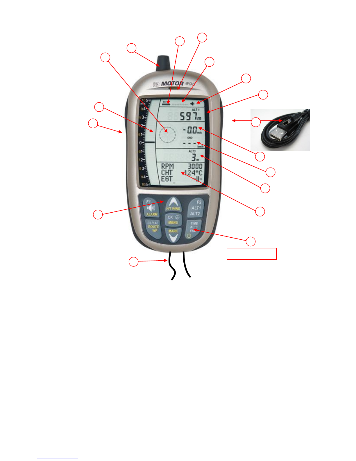
1.1 Instrument overview
1 ON / OFF key
2 Graphics and data Display
3 Differential altimeter / time / flight time /QN
4 Speed
5 Digital vario field
6 USB PC-interface
7 Altimeter field ALT1 / ALT2
8 Audio indicators
9 GPS satellite indicator
10 Loudspeaker port
11 Battery capacity
12 Flylink antenna ( Motor-Box )
13 Compass rose
14 Analogue Vario display
15 Jack for speed sensor
16 Keypad
17 Safety cord
1.1 IQ-MOTOR-eco GPS Switch - on and - off
15
ON / OFF key
6
1
2
3
4
5
7
8
17
16
14
13
12
11
10
9
Operation Manual IQ-MOTOR-eco GPS 5
1.1.1 Instrument Switch-on
The instrument is switched-on by pressing the On/Off key.
To prevent unintentional switch-on, it needs to be acknowledged
upon display prompt: Switch-On?
by pressing the OK key.
Following acknowledgement the display will shift for approx.
15 sec. to the switch-on display screen with following
information:
- Battery state, serial number, pilot’s name, instrument type and
- Software (Firmware) Version.
After switch-on the normal flight screen shall appear with flashing altitude data display. The
device needs approx. two minutes to calculate the precise 3D-GPS position. As soon as
the GPS receives stabilised altitude data, the pressure altimeter is automatically adjusted,
the altitude data display stops flashing and the symbol GPS appears over the GPS data display.
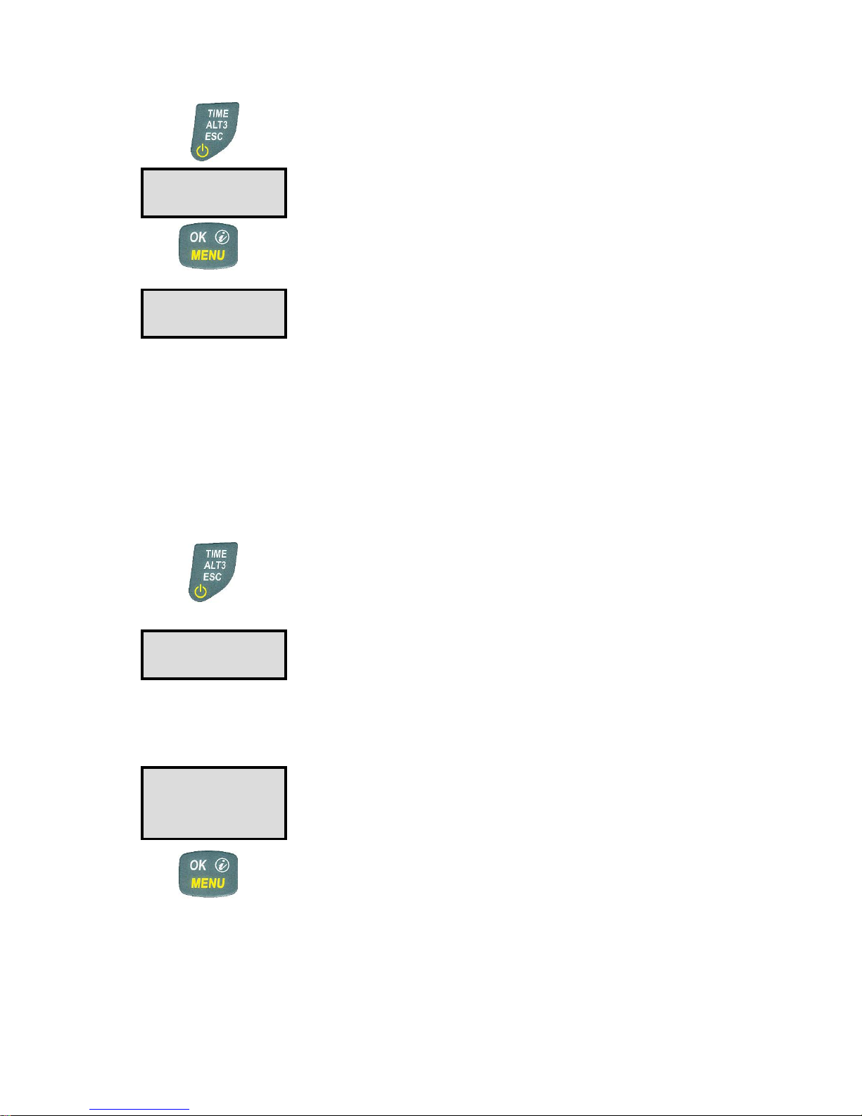
1.1.2 Instrument switch-off / stop flight recording
For switch-off the On/Off key needs to
be pressed until the question: Switch-
off? Press OK is prompted on the
screen.
Again, to prevent unintentional switch-off, also this action needs to
be acknowledged by pressing the OK key!
1. If no flight recording has been programmed, the instrument is
immediately switched-off following acknowledgement by OK.
2. Following an active flight recording the read-out screen
Flight –Analysis is displayed during 60sec. before switch-off.
If you want to quit the flight analysis display early, press shortly the
Off-key, the instrument will then be switched-off immediately.
3. Automatic switch-off: the flight analysis appears
automatically after landing and shall be displayed for about
60sec. Without key stroke the IQ-BASIC-GPS is switched-off
automatically.
4.Automatic switch-off at non-use
If the device does not detect a keystroke or flight related
parameters during 30 minutes, it will be switched-off
automatically.
Switch-On ?
Press OK !
Test Batt.
2.86 V
Switch-off ?
Press OK !
End recording?
Switch-off ?
Press OK !

Operation Manual IQ-MOTOR-eco GPS
1.2 Keypad
1.3 Operation philosophy
The IQ-MOTOR-eco GPS instrument is very easy to handle and intuitive. Just try it a few times,
and you will discover that one can get along very rapidly with the simple menu structure. However,
please note some essential instructions regarding the various functions.
- White key lettering: display screen shifts such as for ex. ALT1 / ALT2, Vario- acoustic settings,
F1 / F2 key commands and the (i) information retrieval, can be performed speedily during the flight
by short pressure on the key.
- Yellow key lettering: by long pressure of 3 sec. important functions may be called up directly
during the flight and may also be edited. The selected function is switched-off after approx.
8 seconds in case of non-use!
- Main menu: all instrument settings, but also Waypoints-, Routes- and flight memory, can be
set prior to the flight via the Main menu (MENU key). It is possible to select within the menu
submenus by use of the up-/down keys and to enter adjustments. The main menu is quitted
automatically at 30 seconds after the last entry.
Tip: all instrument settings of the Main menu can be set comfortably by use of the freebie
PC-Software Flychart on the PC and be transferred via USB-interface onto the instrument.
1.3.1 Function related keys F1 and F2
Both keys F1 and F2 alter their setting possibility according to selected function or readout
screen. The meaning of the related key is indicated on the display screen.
Example: in setmode ALT 1 the function of F1 is "accept GPS altitude" and the function of F2
is to set the altimeter to „FL 1013mB pressure“!
Audio Volume
Alarm Settings
Altitude display
Shift ALT1 / ALT2
Settings altimeter
Shift graphics display
in setting mode up / down
during flight: insert marker into flight
recording / Memorise position as Waypoint
Acknowledgement key OK
Main Menu
iInfo key: display of current
coordinates or of Information
Display shift - time / altitude 3
On/Off key
Escape key
Diff. Altimeter 3 reset to 0
Route or Waypoint
activate / deactivate
Function related key F2
Function related key F1

Operation Manual IQ-MOTOR-eco GPS 7
1.4 Display screen
1.4.1.1 Graphics / data fields display
In normal flight mode it is possible to shift the graph page by short pressure on the keys
▲UP or ▼DOWN. The number of the current page is indicated on the display bottom.
Sequence: ALT, VAR, 1, 2, 3, 4, 5. After switch-on the page of altitude graphics (ALT)
is always displayed.
Altimeter Graphics display
In this graph is illustrated the course of altitude during the past
36 seconds. If the altitude difference is more than 50m, the scale
is automatically adapted. The height scale is displayed on the
right side. (50 /100m)
Variometer Graphics display
In this graph page is illustrated the course of Variometer during
the past 36 seconds. The scale is automatically adapted to the
flight track. The scale values are displayed on the right side.
Digital Vario
with Integrator
Altimeter
ALT1 / ALT2
Current page dot display
Last thermal
Wind direction
Analogue Vario
Sink acoustics
Vario Unit
Battery charge state
Flight recording
Acoustic Volume
Speed display
Compass rose
Direction to WP
Direction North
Different. altimeter
Time / Flight time
QNH
GPS number of Satellites
3-D GPS Fix
Rec
Graphics- and Data field –
display screen
50
ALT
1
0
-1
VAR

Operation Manual IQ-MOTOR-eco GPS
1.4.1.2 Motor data display
For display of motor data on screen 1, 2 and 4, it is necessary that a FlyLink-connection to
FL-motor 2 sensor module is actuated.
Motor data display (1)
Motor rotation speed ( 0 -12 000 rpm)
Cylinder temperature (-20 - 800°)
Exhaust gas temperature (-20 –800°)
Navigation data display (2)
Current track
Bearing to take-off
Distance to take-off
Motor data display - digital / analog (3)
Motor rotation speed ( 0 - 12000 rpm )
Cylinder temperature ( -20 - 800°C )
Motor temperature data display - digital / analog (4)
Cylinder temperature (-20 - 250°)
Exhaust gas temperature (-20 –800°)
Remark: if no FlyLink connection is available, or if FlyLink is deactivated, the following indication
shall appear on display screen 1, 3 and 4:
Display indication if no connection to sensor module is existing.
Display indication if FlyLink radio connection on the flight instrument is deactivated.
1
RPM 5600 1
CHT 180°C
EGT 560°C
- 1
2
Kurs 325 1
Tk-off 120
Dist. 26
- 1
RPM 5600
CHT 165°
- 1
CHT 165°C
EGT 620°C
- 1
4
1
FL-Motor 2 1
suche
12345
- 1
1
FL-Motor 2 1
Aus
- 1

Operation Manual IQ-MOTOR-eco GPS 9
1.5 The setting menus
By long pressure on the MENU key access is given to the Menu setting mode. Using the keys ▼
and ▲ one of the Menu items (flashing line) is selected and pressing the OK key gives access to
the corresponding menu or submenu.
Flashing values can be modified by use of
the ▲UP or ▼DOWN key. By pressing the
OK key the setting is memorised. Using the
ESC (escape) key operates the return to the
normal flight display screen. If there is no
keystroke effected during 30sec., the
instrument returns automatically to the flight
display screen.
1.5.1 Instrument settings
All settings, such as pilot’s name, time zone, battery type, as also all units for display of altitude,
speed, temperature etc., can be adapted and adjusted according to personal preferences under
Main Menu
Instrument settings.
1.5.1.1 Keypad functions for text - input / editing
After call-up of Menu Pilot name, Glider type or ID, the
1st digit of the name is flashing. By use of softkeys and
the required character is selected, there are numbers,
letters, as also a series of special characters available for
selection.
By use of keys one moves to the next or to the
previous letter.
By use of key A-a-1-& it is possible to shift between
capitals and small letters, as also between numbers and
special characters.
By long pressure on the same key one character is
deleted (Rub out).
The name can be up to maximum 16 characters long.
By use of key OK the entry of one line is saved and the
cursor jumps to the next line.
Tip: by use of the PC Flychart software it is possible to set easily and comfortably all instrument
characteristics, as also to save and store the data in a file. It is also possible to manage several
instrument settings, which can be transferred back again to the IQ Motor ECO-GPS at any time.
<Name
not-set
abc...
zyx…
Flytec
Flytec
A-a-1
Escape
OK
Speichern

Operation Manual IQ-MOTOR-eco GPS
1.5.2 Menu Overview
Menu
Display IQ
Motor
Setting range
Page
Flight memory
FlightMemo
25
>Flights (Flight memory)
Flights
25
> Recording interval
Rec Interv
1 –60 sec.
25
> Recording mode
Rec Mode
Auto / Manual
> Delete all flights
Delete
25
FL Motor 2 FlyLink
FL Motor 2
21
> FL Reception on / off
On /off
20
> FL Box No.
0 - 65500
20
> RPM Alarm
RPM Alarm
0 –13000 rpm
22
> CHT Temp. Alarm
CHT Alarm
0 - 250 °C
22
> EGT Temp. Alarm
EGT Alarm
0 - 800 °C
22
Variometer
Variometer
14
>Digital Vario Integrator
Digital
1 –30 Sec.
14
>Basic filter
Filter
0 –1 –2 –3
15
>Threshold last Thermal
Threshold L
0,5 –3,0 m/s
15
Climb Acoustics
Climb Acoust
16
>Climb Threshold
Climb Thresh
0 –20 cm/s
16
>Basic Frequency
BasicFreq
600 –1400 Hz
16
>Frequency Change
Freq Change
0 –1 –2 –3 –4
16
>Pitch Change
Pitch Change
0 –1 –2 –3 –4 –
5
16
>Pitch Mode
Pitch Mode
lin. / exp.
16
>Pre Thermal Threshold
PThermThre
sh
0 bis -1,0m/s
16
Sink Acoustics
Sink Acoust
17
>Sink Threshold
Sink Thresh
- 0.1 … 20.0 m/s
17
>Basic Frequency
BasicFreq
300 –1000 Hz
17
>Sink Alarm
Sink Alarm
- 0.1 … 99.9 m/s
17
Speed
Speed
>Stall Alarm
Stall Alarm
0 –10 … 99 km/h
18
>Wind vane corr.
Correktion
50…100 … 150
18
Pilot
Pilot
28
>Pilot’s name
Name
16 characters
28
>Glider Type
Glider Type
16 characters
28
>Glider ID
Glider ID
16 characters
26
Instrument Settings
Inst Sett
>Time zone
Time Zone
+/- 13 Std.
28
>Alt 2 Mode
Alt 2 Mode
GPS / FL / Inv.A1 /
Relativ /
13
>Units
Units
Altimeter
Altitude
m / ft.
Speed / Distance
Speed
Dist.
kmh / mph / kt
Temperature
Temperatu
re
°C / °F
Pressure
Pressure
hPa / inHg
Vario
Vario
m/s / ft.Min*100
Distance
Distance
Km / miles
Time
Time
12h / 24h
Coordinates format
Coordinat
es
dd.ddddd /
dd’mm.mm /

Operation Manual IQ-MOTOR-eco GPS 11
dd’mm’ss
Factory settings
>Pressure sensor zero point
Press.
Offs.
+/- 10 hPa
> Set instr. to original condition
Org.
Cond.
Original condition
> Device / PCB No.
S/N No.
Info SN No. / PCB
No.
> Sensor Adjustment
Intern
Code

Operation Manual IQ-MOTOR-eco GPS
2 Functions
2.1 Altimeter and atmospheric pressure
The IQ-MOTOR-eco GPS provides 3 altitude displays and 1 QNH pressure indicator.
ALT1
The altimeter absolute altitude shows the altitude over sea level. (meter „m“ or feet „ft“)
ALT2
alternatively: - GPS altitude
- Flightlevel pressure altimeter display in relation to 1013hPa
- meter or feet inverse to ALT1 (Absolute A1)
- Relativ Altimeter
ALT3
The altimeter relative altitude shows the altitude towards a reference point.
QNH
Actual air pressure at sea level in relation to ALT1
2.1.1 Altimeter Alt1, absolute altitude
Shifting between display screens Alt1 and Alt2 is effected by shortly
pressing the Alt1/Alt2 key.
Altitude display Alt1 indicates always the absolute pressure altitude above sea level.
After switch-on the altimeter ALT1 is automatically adjusted to GPS altitude by the instrument.
After switch-on the display is flashing until the GPS-receiver has calculated a precise
altitude for adjustment.
Units m / ft. - re-setting: see Menu
Instrument settings
Units
2.1.1.1 Manual setting of altimeter Alt1
Set mode A1 of altimeter is called-up by long pressure on the ALT1
key. The possible settings are shown in the information field.
By brief pressure on one arrow key the readout value can be adjusted
meter by meter. Under keystroke the display shall be
changed automatically until the key is released.
Due to this adjustment the QNH display is also altered.
Adopt GPS altitude with F2 key
By brief pressure on the F2 key it is possible to adopt the GPS
altitude. Please consider that the GPS-receiver does not always provide
the reliable altitude value! In case of poor Satellite constellation or bad
reception, altitude deviation of +/- 50 m will occur!
Setting altitude to pressure standard 1013hPa with F1 key
By brief pressure on the F1 key the altitude is set to 1013hPa (Flightlevel).
Tip: If the user does not know the altitude of his present location, he may operate
the QNH field and, using the arrow keys, by changing the altitude value until it matches
the actual QNH as per weather forecast or indication issued by air traffic management.
2.1.2 Altimeter display Alt2
Shifting between display screens Alt1 and Alt2 is performed by briefly
pressing the key Alt1/Alt2.

Operation Manual IQ-MOTOR-eco GPS 13
The following values can be displayed on the altimeter screen ALT 2:
GPS Alt. = display of GPS altitude
Flight-Level =Flightlevelaltitude in ft relatingto 1013 hPa e.g. display Fl 14 stands for being in
Flight Level 1400 ft ( display in steps of 100 ft )
ALT1 m/ft-Inv= display of altitude ALT1 inverse to unit of ALT1 in ft or m
Relative = the relative altimeter displays altitude with reference to a point.
Altitude setting of this point of reference can be set in A2 set mode at
anytime.
2.1.2.1 Manual setting of altimeter Alt2 (A2 relative mode)
Prolonged pressure on the ALT2 key during ALT2-display activates the instrument into
setting mode.
By briefly pressing one arrow key the display indicator can be adjusted meter by meter.
The displayed value is changed automatically as long as the key is pushed until it is
released.
Tip: the relative altimeter can be used for example for measuring the superelevation above
landing site. For this purpose ALT2 will be reset to zero related to the landing site altitude.
2.1.2.2 Altimeter display Alt2 - definition
Altimeter A2 mode can be defined in the menu (Main Setup Menu
Instrument Settings
Alt2 mode).
Tip: in altimeter display screen ALT2 altitude ALT1 can be selected in ft (inverse to unit ALT1
in m). This information may be of importance when being in contact with the air traffic controller of
Restricted Areas (CTR’s).
2.1.3 Altimeter display Alt3 (differential altimeter)
Altimeter Alt3 is in any case a differential altimeter. It indicates always the difference in regard
to the altitude value on which it has been reset to zero for the last time. This function is often
required to measure the elevation above the start site, or to detect easily during the flight in a
weak thermal the height gain –or loss.
Example: altitude ALT3 is set automatically to 0 m at start site, after take-off the altitude
display Alt3 shall always indicate the altitude above start site.
Reset altitude ALT3 to 0m
By brief pressure on the CLR ALT3 key the altitude ALT3 may be reset to 0m at any time.
Operation Manual IQ-MOTOR-eco GPS
2.2 Variometer functions
2.2.1 Analog-Vario
The most important indication for a non-motor driven
aircraft is without any doubt the Variometer.
It displays the vertical speed in meter/second and informs
the pilot about the actual climb or sink rate.
It is only possible for the pilot by using the Vario (and its
accompanying acoustics) to determine the most efficient
thermal climb, and in the opposite situation, to recognise
when he is sinking too rapidly in downwind which he should
leave at best speed.
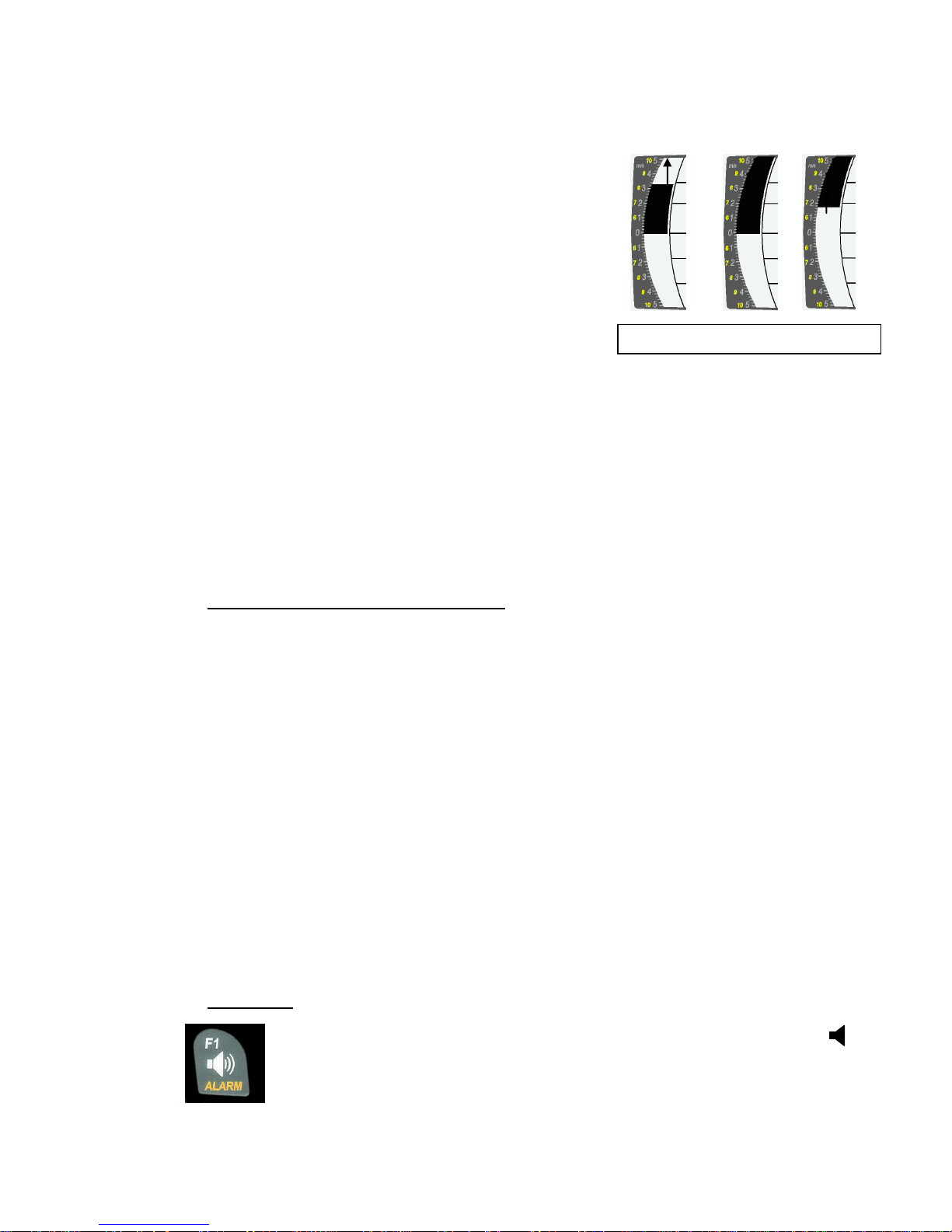
The scale of the analogue display is consistently 0,2 m/s over both scale ranges! (Flytec AG Patent!)
The range of the first scale extends from 0 up to +/- 5m/s. Thereafter the scale display switches
automatically to the second scale range which extends from 5 up to 10m/s. The second scale is
afterwards displayed with a white bar on black field.
2.2.2 Digital-Vario (average value-Vario)
The Digital Vario has a scale of 10 cm/s and an extensive measuring range of up to +/- 100 m/s.
It is therefore also appropriate to display and record even measuring flights up to the free fall.
2.2.2.1 Average value-Vario (integrating Vario)
The digital Vario display can be set under Main Setup Menu
Variometer
Digital as average
value Vario (also designated as integrating Vario) with a time constant of 1 to 30s. The values are
recalculated per second and indicate the average value of climb or sink rate within the adjusted time
span. At gruff narrow hillside up-wind this helpful readout may be used to determine if a circle or aft
flight would provide better climb values. Integration time should be selected more longer in accordance
to the thermal’s roughness.
Based upon practical experience, we recommend an average value of 5 - 10 seconds.
2.2.3 Variometer Acoustics and volume level (Sound)
In order to enable the pilot to follow the current climb- resp. sink rate without looking on the
instrument, the Vario-Acoustics generate a tone sequence dependent on the value data.
It varies in relation to climb- and sink rate in tone pitch, as well as for interval frequency
(number of beep tones per second).
The Vario-Acoustic corresponds always to the value of Analogue-Vario and is therefore
reproducing the direct values, i.e not the average values being selected in the digital Vario
readout screen.
The Variometer Climb- and Sink Acoustics can be adapted with high flexibility on the IQ-BASIC-GPS
in manifold fields to one’s individual and personal requirements.
2.2.3.1 Audio level
By use of the key Audio level the sound volume of the built-in loud speaker is
adjusted. Indeed five sound levels may be set, from soundless to maximum
sound volume. The selected value is displayed with the Audio Symbol and is
confirmed with a short beep or double-beep. The selectable sound levels are:
0 - 25% - 50% - 75% - 100% - 0.
Short pressure on the Audio Level-key shall increase the volume level each time
by 25 %.
Vario 3.2 5,0 6.8m/s

Operation Manual IQ-MOTOR-eco GPS 15
2.2.4 Menu Settings Variometer
Tip: By use of the PC Software Flychart Extras -> Flight instrument Options, all instrument
characteristics can be set easily and comfortably.
By use of the feature tone simulation the adjusted values can be checked easily!
2.2.4.1 Digital-Vario Integrator
Main Setup Menu
Variometer
Digital
Setting of average value time constant from 1 –30 seconds for the digital Variometer display.
2.2.4.2 Threshold value last thermal
Main Setup Menu
Variometer
Threshold for the display arrowhead of last thermal, the range can be set between 0,5 up to 3 m/s.
The thermal arrowhead in the compass rose points to the direction, where the integrated Vario was
the last time higher than this threshold value.
2.2.4.3 Basic filter (Turbulence filter)
Main Setup Menu
Variometer
Filter .
The response characteristics of Variometer display and of climb- or sink acoustics can be adapted
within a wide range in accordance to the pilot’s needs or the weather conditions.
In order to simplify the settings, Flytec has defined 4 basic- resp. turbulence filters.
Variometer - sensitivity / response characteristics
Filter No.
0
weak filtering
for very calm air in Winter
1 Default
normal filtering
for enjoyment thermal with light turbulence
2
high filtering
thermal with turbulence
3
very high turbulence filtering
for very rough and strong thermal
2.2.5 Variometer - Acoustic settings
The climb tone is a frequency modulated beep tone whose pitch and beep tone sequence rises
rhythmically at increasing climb rate. The pulse/pause ratio is 1:1.
Following settings are possible under Main Setup Menu
Variometer Climb Acoustic and
Variometer Sink Acoustic:
Climb Acoustic settings:
Climb threshold: = climb acoustic threshold
Basic frequency = basic tone pitch Vario climb
Frequency change = increase of tone pitch
(frequency modification per m/s)
Pitch modification = increase of beep interval per m/s
Pitch mode = linear or exponential
increase of climb acoustic
Pre-Thermal Threshold: = trigger point of Pre-Therm.acoustic
Sink Acoustic settings:
Sink threshold: =Sink tone threshold
Basic frequency =basic tone pitch Vario sink
Sink Alarm =Sink alarm threshold
Climb
Sink
Sink
tonealarm
Climb accou.
threshokd
Climb tone
0m/s
Sinktone
threshold
Pre Thermal
threshold
Soundloss
range

Operation Manual IQ-MOTOR-eco GPS
2.2.6 Variometer –climb acoustic
2.2.6.1 Climb acoustic threshold
Main Setup Menu
Variometer Climb Acoustic
Climb threshold
In order to avoid the climb acoustics get started with immobile aircraft, for ex. at take-off area, or at only
slight climb, the climb acoustics starting point can be set in the range from 0 cm/s up to 20 cm/s.
2.2.6.2 Basic frequency
Main Setup Menu
Variometer Acoustic
Basic frequency
The frequency audible at starting climb tone.
Range: 600 -1400 Hz (factory setting 700 Hz)
2.2.6.3 Variometer climb acoustic Frequency change
Main Setup Menu
Variometer Acoustic
Frequency change
The interrelation may be seen on graphic below.
Range: 0 up to 4 (factory setting 2)
2.2.6.4 Variometer Climb acoustic Pitch change / increase of tone interval per m/s
Main Setup Menu
Variometer Acoustic
Pitch change
Main Setup Menu
Variometer Acoustic
PitchMode
The interrelation may be seen on graphic below.
Range: 1 up to 5 (factory setting 2)
0
2
4
6
8
10
12
14
500
1'000
1'500
2'000
2'500
3'000
m/s
Hz
5 = Strong beep tone interval alteration
per m/s Vario alteration
1 = Weak beep tone interval alteration per
m/s Vario alteration
Number of
beep tones
per second
Basic tone pitch 600 Hz
Tone pitch only weakly
increasing per m/s Vario
alteration. Setting = 0
Tone pitch strongly increasing
per m/s Vario alteration.
Setting = 4
0
2
4
6
8
10
12
14
5
10
15
20
25
30
m/s
= Tone interval change exponential
( Strong change from 0 –2 m/s

Operation Manual IQ-MOTOR-eco GPS 17
2.2.7 Pre-Thermal Acoustic Threshold
Main Setup Menu
Variometer Climb Acoustic
PThermalLim
At this position it is possible to activate a „Pre-zero“ climb acoustic signal!
The trigger point of this acoustic signal can be adjusted within the range of -1,0m up to 0 cm/s. The
„Pre-zero Acoustic“ is particularly useful in the level flight range! The sound differs clearly from
climb- and sink vario!
2.2.8 Variometer –sink acoustics
2.2.8.1 SinktoneF = Basic Tone pitch Variometer Sink
Main Setup Menu
Variometer Acoustic
Basic frequency
The basic tone pitch is the pitch at starting sink tone. The sink tone is discreetly heard with deeper
sound pitch at increasing sink speed, and is slowly increasing in frequency again when approaching
rising air. The basic tone pitch of sink acoustics may only be set equally to the basic tone pitch for
climb acoustics.
Sinktone threshold
Main Setup Menu
Variometer Acoustic
Sinktone Threshold
Application point As for climb acoustics, the application point of sink acoustics can be selected.
The threshold can be set by use of the upand downarrow keys
between -0,1 and -20,0m.
During flight the sinktone can be switched-on or switched-off
by prolonged pressure on the key Alarm Sinktone by use of the
keys F1 / F2.
Sink Alarm threshold
Main Setup Menu
Variometer Acoustic
Sinkalarm threshold
The sink alarm is a continuous tone which sounds upon reaching the sink alarm threshold.
Application point The alarm threshold can be set by use of the upand downarrow keys
between -0.1 and -20m.
During flight the sinktone can be switched-on or switched.-off by
prolonged pressure on the key Alarm Sinktone by use of the
keys F1 / F2.
Tip: by use of the PC-Software Flychart 4.52 Extras –Flight instrument Options -> Acoustic,
all Vario acoustic characteristics can be set easily and comfortably.

Operation Manual IQ-MOTOR-eco GPS
2.3 Speed
Apart from Vario and altitude the flight through the air (= Airspeed) is indeed one of the decisive
messages. By use of a precisely indicating speedometer it is possible to increase air safety.
2.3.1 Wind vane sensor
The IQ-MOTOR-eco GPS is provided with a very precise speed measuring system, i.e. one entry
with evaluation electronics for Flytec wind vane sensors. Advantage: wind vane sensors trigger
correct readout already from approx. 1 km/h speed, these sensors are also perfectly suitable for
detection of weakest wind strength values at starting site. (Wind vane sensor optional)
The speed indicator can be precisely gauged by correction factor.
Factory setting is 100%by default.
Main Setup Menu
Speed
Sensor setting wind vane
Due to these speed dependent correction factors it is possible to slightly rectify faulty
measurements caused by inappropriate placing of the sensor inside lee position, or of the blister
in front of the body.
The wind vane sensor measures the true airspeed (True Airspeed = TAS).
With plugged wind vane sensor the speed indicator shifts from GND to AIR (airspeed).
GND speed is displayed on page 4 together with the glide ratio air and glide ratio ground.
Remark: page 4 can only be selected with plugged wind vane sensor.
2.3.2 Stallalarm
This function is only enabled when using the optional wind vane sensor.
This alarm is consisting of a deep tone with short beeps and always with 100% sound level.
Under Main Setup Menu
Speed
Stallalarm it is possible to determine the speed of stallalarm.
If the stall alarm is set to the value of 0 km/h, the alarm is then switched-off.
During flight the stall alarm can be switched-on or switched-off by
prolonged pressure on the key Alarm Stall by use of the keys F1 / F2.
2.3.3 Speed without speed sensor
Frequently pilots fly without any speed sensor. In this case only the speed over ground
(GPS speed) shall be displayed.

Operation Manual IQ-MOTOR-eco GPS 19
2.4 Time of day and Date
Remark: time of day and the date do not need to be adjusted. They are taken automatically from
the GPS-Receiver. However, any time zone difference from UTC (World Time) needs to be
entered with a positive value if the time zone is located East of Greenwich, or a with a negative
value, if it is at the West of it. Time zones with 0.5h UTC offset are also adjustable.
This setting is entered with Main Setup Menu
Instr. Settings
Timezone.
Important: all internal calculations of the instrument are made in UTC (Coordinated Universal
Time). The local time is just used as „Time“ display and calculates simply the UTC plus or minus
the UTC offset.
For the time of take-off the local time is binding.
2.4.1 Flight duration (flight time)
The take-off time is automatically recorded. For this purpose the GPS needs to be activated.
Moreover, only flights which are lasting more than 2 minutes are log recorded.
The flight time and all min. / max. values are presented on the Info page short pressure
on the key i- Info. After 20sec. the previous display screen shall automatically reappear again.
See also page: 25 Flight logbook and Flight Analysis .
The unit will also recognise autonomously the end of the flight. It is the basic condition for the end of
the flight that neither speed over ground has been measured with more than 10 km/h during min. 60s,
nor that the Vario has pointed to more than 0.1 m/s.
2.5 Temperature
The IQ-MOTOR-eco GPS is provided with a temperature sensor for the temperature
compensation of pressure sensors, as well as for the automatic display contrast control.
Temperature reading is possible in degree Centrigrade or Fahrenheit. Main Setup Menu
Instr. Settings
Units. Remark: the temperature sensor measures the internal circuit board
temperature, but in no way the outside air temperature! The inside temperature of the casing may
be higher or lower than the ambient air temperature, especially when the instrument is exposed to
direct sunlight.
The Temperature is displayed on Page 1.

Operation Manual IQ-MOTOR-eco GPS
3 Motor data from radio sensor FL-Motor 2
The IQ MOTOR-eco GPS is fitted with a FlyLink® transmitting- and reception module and is
therefore capable to receive and to analyze the data of motor rotation speed and also both
temperatures CHT (Cylinder head temperature) and EGT (Exhaust gas temperature) from the
radio sensor module FL Motor 2.
Caution: important remark!
Modern high-performance ignition systems, such as utilized on a large number of para-
motor systems, generate partially extreme HF interference pulses. These interferences
may be very disturbing for the radio transmission from the FlyLink transmitter to the Vario.
Obviously we have mounted extensive HF filters, but in rare cases disturbances may
in fact be very strong, so that no safe signal transmission will be possible!
Sometimes the careful grounding of the ignition system to the motor housing will remedy.
We recommend to examine this ground connection when using the FlyLink transmitter
and to carefully complete, if applicable!
Moreover, another positioning of the FlyLink module, such as a modified cable duct,
may solve the problem.
3.1 FlyLink®
FlyLink
is an up-to-date radio network surrounding the pilot. FlyLink devices must be registered
with the serial number in the flight instrument, in order to be recognised by the instrument.
Basic settings for FlyLink can be entered in Menu
FL Motor FlyLink. Upon delivery there are
factory settings existing, which maybe adapted to one’s personal preferences.
Factory settings:
Flylink ID number : S/N Number of supplied radio sensor module
CHT Alarm: 200°C - Alarm On
EGT Alarm: 600°C - Alarm On
Table of contents
Other Brauniger GPS manuals

Brauniger
Brauniger AV-PILOT User manual

Brauniger
Brauniger IQ Motor+ User manual

Brauniger
Brauniger IQ-Compeo+ How to use

Brauniger
Brauniger IQ-BASIC-GPS User manual

Brauniger
Brauniger iq basis User manual

Brauniger
Brauniger AV Pilot II User manual

Brauniger
Brauniger IQ-BASIC-GPS How to use

Brauniger
Brauniger IQ-CLASSIC User manual


