BRAVILOR BONAMAT Chiller User manual

Chiller
700.403.353 B
COFFEE BREWING MACHINES
MACHINES A CAFE
KAFFEEBRUEHMASCHINEN
KOFFIEZETAPPARATEN
E02-2003

C
B
D
F
G
H
A
E
M
N
C1
C2
C3
C4
L
I
J
K
Fig. 1 Principal components and Control organs

J
K
Fig. 1 Belangrijke onderdelen en bedieningsorganen
200
245
35 415
482
755
115
W=78
E=154
572
E/W = 61
Fig. 2 Dimensions

GB
Bravilor
Bonamat
Operating instructions
CHILLER
Chilled water dispenser
Bravilor Bonamat
Pascalstraat 20
1704 RD Heerhugowaard
The Netherlands
700.403.353C/07−2006
2006 BravilorBonamat

GB
2006 BravilorBonamat
All rights reserved.
No part of this document may be reproduced and/or published by means of print, photoprint,
microfilm or any other means without prior written permission from the manufacturer.
The foregoing applies also to the figures and/or diagrams contained herein.
The information provided in this document is based on general data that we were aware of
at the time of publication, relating to constructions, properties of materials and working
methods, and this document is therefore subject to modifications. For this reason, the
instructions presented here should merely be seen as a set of guidelines for installing, using
and maintaining the device indicated on the front page of this document.
This document is valid for the standard version of the device. Consequently, the
manufacturer cannot be held liable for any damage resulting to a device supplied to you with
specifications that deviate from the standard version.
Although this document was compiled with the greatest possible care and attention, the
manufacturer cannot be held responsible for any errors contained within this document or for
any of the consequences that may derive from these errors.
PLEASE TAKE SOME TIME TO READ THIS DOCUMENT AND THE SAFETY BROCHURE
(700.403.347) CAREFULLY BEFORE PROCEEDING TO USE THE DEVICE.
ALWAYS STORE BOTH DOCUMENTS IN THE VICINITY OF THE DEVICE.

GB
ECopyright Bravilor Bonamat B.V. I
version 1.0
FOREWORD
Using this document
BEFORE USE OF THE APPARATUS FIRSTLY READ THE SAFETY BROCHURE (700.403.347).
Pictograms and symbols
This document contains the following pictograms and symbols:
TIP
Suggestions and advice for conducting the procedures in question more easily.
READ!
Read the safety brochure (700.403.347).
CAUTION!
Procedures which −if they are not conducted with due care and attention−may result in damage to the
device, the surrounding area or the environment.
WARNING
Procedures which −if they are not conducted with due care and attention−may result in serious
damage to the device or physical injury.
WARNING
Danger: electric current.
Related documents
The following related documents are available:
−Warnings, safety regulations and information concerning the protection
of the environment: :700.403.347
−Chiller maintenance manual :700.703.Kxx
Document code
Document codes are composed of two fields:
−field 1: document number
−field 2: revision date (possibly followed by the revision number).

GB
version 1.0 ECopyright Bravilor Bonamat B.V.
II
Service and technical support
Please contact your dealer for information relating to specific settings, maintenance or repair activities
that are beyond the scope of this document. Your dealer is always prepared to assist you. Please
ensure that you have the following data available:
−model code
−type number
−serial number
These data are found on the device identification label (fig.3 ).
Conditions of warranty
The conditions of warranty applicable to this machine form part of the terms of delivery.
Identification of the device
DSee fig.3
A. model code
B. type number
C. serial number
D. power
E. frequency
F. supply voltage
DEF
A B C
Fig. 3 Contents of machine identification plate

Table of contents
GB
ECopyright Bravilor Bonamat B.V. III
version 1.0
FOREWORD I. . . . . . . . . . . . . . . . . . . . . . . . . . . . . . . . . . . . . . . . . . . . . . . . . . . . . . . .
Using this document I. . . . . . . . . . . . . . . . . . . . . . . . . . . . . . . . . . . . . . . . . . . . . . . . . . . .
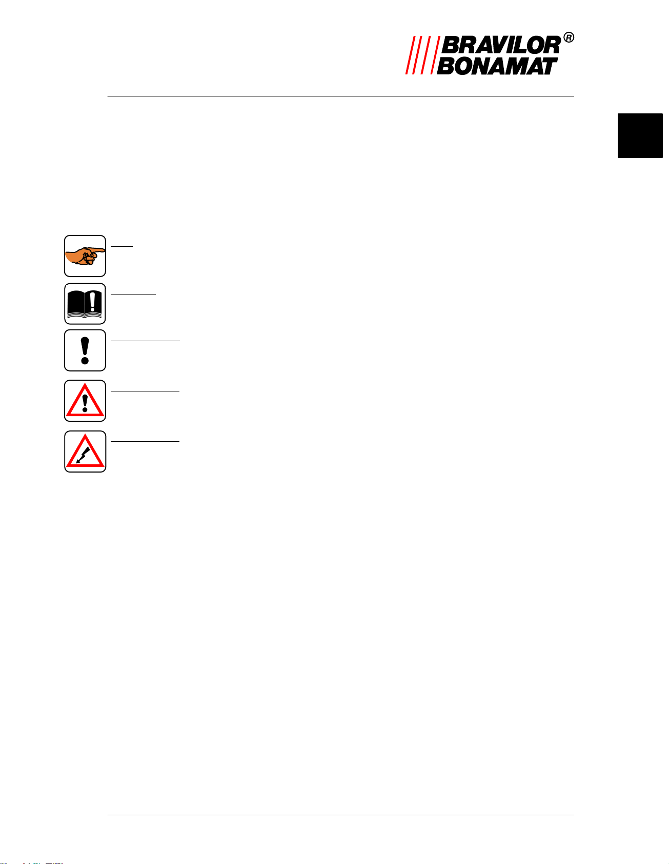
Pictograms and symbols I. . . . . . . . . . . . . . . . . . . . . . . . . . . . . . . . . . . . . . . . . . . . . . . . . . . . . .
Related documents I. . . . . . . . . . . . . . . . . . . . . . . . . . . . . . . . . . . . . . . . . . . . . . . . . . . . . . . . . . .
Document code I. . . . . . . . . . . . . . . . . . . . . . . . . . . . . . . . . . . . . . . . . . . . . . . . . . . . . . . . . . . . . .
Service and technical support II. . . . . . . . . . . . . . . . . . . . . . . . . . . . . . . . . . . . . . . . . . . . . . . . . .
Conditions of warranty II. . . . . . . . . . . . . . . . . . . . . . . . . . . . . . . . . . . . . . . . . . . . . . . . . . . . . . . .
Identification of the device II. . . . . . . . . . . . . . . . . . . . . . . . . . . . . . . . . . . . . . . . . . . . . .
1. Introduction 1. . . . . . . . . . . . . . . . . . . . . . . . . . . . . . . . . . . . . . . . . . . . . . . . . . . . .
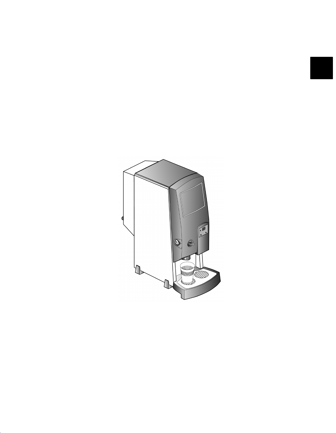
1.1 A brief overview of the device 1. . . . . . . . . . . . . . . . . . . . . . . . . . . . . . . . . . . . .
1.1.1 General description 1. . . . . . . . . . . . . . . . . . . . . . . . . . . . . . . . . . . . . . . . . . . . . . . . .
1.1.2 Main components 1. . . . . . . . . . . . . . . . . . . . . . . . . . . . . . . . . . . . . . . . . . . . . . . . . . .
1.2 Summary of operations 1. . . . . . . . . . . . . . . . . . . . . . . . . . . . . . . . . . . . . . . . . . .
1.2.1 Cold−water system 1. . . . . . . . . . . . . . . . . . . . . . . . . . . . . . . . . . . . . . . . . . . . . . . . . .
2. Technical data 2. . . . . . . . . . . . . . . . . . . . . . . . . . . . . . . . . . . . . . . . . . . . . . . . . . .
2.1 General 2. . . . . . . . . . . . . . . . . . . . . . . . . . . . . . . . . . . . . . . . . . . . . . . . . . . . . . . . . .
2.2 Transport dimensions and weights 2. . . . . . . . . . . . . . . . . . . . . . . . . . . . . . . . .
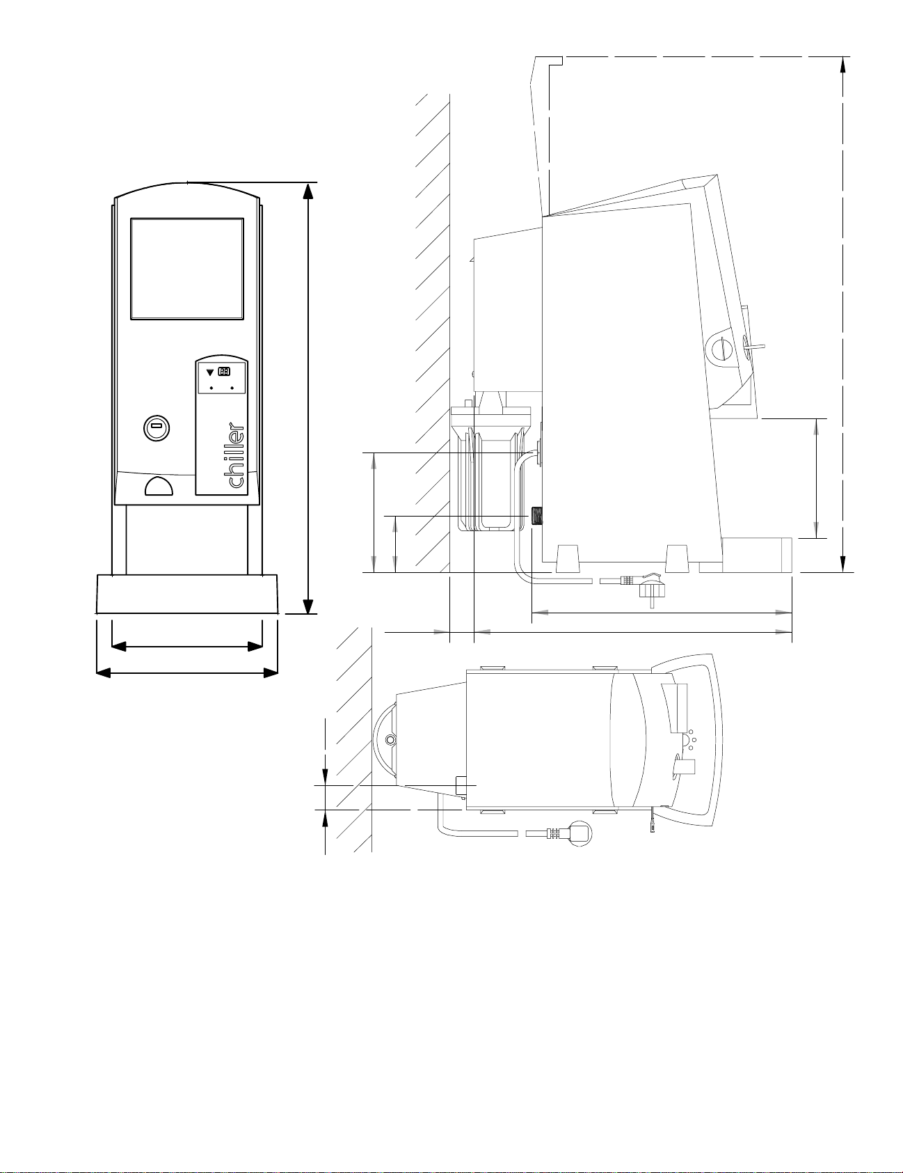
2.3 Dimensions 2. . . . . . . . . . . . . . . . . . . . . . . . . . . . . . . . . . . . . . . . . . . . . . . . . . . . . .
2.4 Electrical system 2. . . . . . . . . . . . . . . . . . . . . . . . . . . . . . . . . . . . . . . . . . . . . . . . .
2.5 Water system 2. . . . . . . . . . . . . . . . . . . . . . . . . . . . . . . . . . . . . . . . . . . . . . . . . . . . .
2.6 Recommended cleaning fluids and liquid disinfectants 2. . . . . . . . . . . . . .
3. Installation 3. . . . . . . . . . . . . . . . . . . . . . . . . . . . . . . . . . . . . . . . . . . . . . . . . . . . . .
3.1 Unpacking 3. . . . . . . . . . . . . . . . . . . . . . . . . . . . . . . . . . . . . . . . . . . . . . . . . . . . . . . .
3.2 Installation 3. . . . . . . . . . . . . . . . . . . . . . . . . . . . . . . . . . . . . . . . . . . . . . . . . . . . . . .
3.2.1 Connecting the drip−tray to the drain (optional) 3. . . . . . . . . . . . . . . . . . . . . . . . . .
3.2.2 Using the device the first time 3. . . . . . . . . . . . . . . . . . . . . . . . . . . . . . . . . . . . . . . .
4. Everyday usage 4. . . . . . . . . . . . . . . . . . . . . . . . . . . . . . . . . . . . . . . . . . . . . . . . .
4.1 Signalling and display 4. . . . . . . . . . . . . . . . . . . . . . . . . . . . . . . . . . . . . . . . . . . . .
4.2 Operation 4. . . . . . . . . . . . . . . . . . . . . . . . . . . . . . . . . . . . . . . . . . . . . . . . . . . . . . . .
4.2.1 Drawing off cold water 4. . . . . . . . . . . . . . . . . . . . . . . . . . . . . . . . . . . . . . . . . . . . . . .
5. Maintenance by specially autorized personnel 6. . . . . . . . . . . . . . . . . . . .
5.1 General cleaning 6. . . . . . . . . . . . . . . . . . . . . . . . . . . . . . . . . . . . . . . . . . . . . . . . . .
5.2 Flushing the cold−water system 6. . . . . . . . . . . . . . . . . . . . . . . . . . . . . . . . . . .
5.3 Cleaning the cold−water reservoir and replacing the water filter 6. . . . .
5.3.1 Cleaning procedure for the cold−water reservoir 6. . . . . . . . . . . . . . . . . . . . . . . . .
6. Programming 8. . . . . . . . . . . . . . . . . . . . . . . . . . . . . . . . . . . . . . . . . . . . . . . . . . .
6.1 Programming facilities 8. . . . . . . . . . . . . . . . . . . . . . . . . . . . . . . . . . . . . . . . . . . .
6.1.1 Programming buttons 8. . . . . . . . . . . . . . . . . . . . . . . . . . . . . . . . . . . . . . . . . . . . . . . .
6.1.2 Menus (P1, P2, P3 and P4) 8. . . . . . . . . . . . . . . . . . . . . . . . . . . . . . . . . . . . . . . . . .
6.1.2.1 General procedure 8. . . . . . . . . . . . . . . . . . . . . . . . . . . . . . . . . . . . . . . . . . . . . . . . . .
6.1.2.2 P1 Temperature setting 8. . . . . . . . . . . . . . . . . . . . . . . . . . . . . . . . . . . . . . . . . . . . . .
6.1.2.3 P2 Displaying the number of litres drawn off 9. . . . . . . . . . . . . . . . . . . . . . . . . . . .
6.1.2.4 P3 Filter−replacement status 9. . . . . . . . . . . . . . . . . . . . . . . . . . . . . . . . . . . . . . . . .
6.1.2.5 P4 Display of the number of litres drawn off 9. . . . . . . . . . . . . . . . . . . . . . . . . . . .
7. Correcting malfunctions 10. . . . . . . . . . . . . . . . . . . . . . . . . . . . . . . . . . . . . . . . .
7.1 General 10. . . . . . . . . . . . . . . . . . . . . . . . . . . . . . . . . . . . . . . . . . . . . . . . . . . . . . . . . .
7.2 Display messages and their meaning 11. . . . . . . . . . . . . . . . . . . . . . . . . . . . . .
8. Ordering consumables and accessories 12. . . . . . . . . . . . . . . . . . . . . . . . . .
8.1 Consumables 12. . . . . . . . . . . . . . . . . . . . . . . . . . . . . . . . . . . . . . . . . . . . . . . . . . . . .
8.2 Accessories 12. . . . . . . . . . . . . . . . . . . . . . . . . . . . . . . . . . . . . . . . . . . . . . . . . . . . . .

Table of figures
GB
ECopyright Bravilor Bonamat B.V.
IV version 1.0
Fig. 3 Contents of machine identification plate II. . . . . . . . . . . . . . . . . . . . . . . . . . . . . . . . . . . . . . . . . . . .
Fig. 4 Signalling and display 4. . . . . . . . . . . . . . . . . . . . . . . . . . . . . . . . . . . . . . . . . . . . . . . . . . . . . . . . . . .
Fig. 5 Cleaning the cold−water reservoir 5. . . . . . . . . . . . . . . . . . . . . . . . . . . . . . . . . . . . . . . . . . . . . . . . .
Fig. 6 Water filter 7. . . . . . . . . . . . . . . . . . . . . . . . . . . . . . . . . . . . . . . . . . . . . . . . . . . . . . . . . . . . . . . . . . . . .
Fig. 7 Programming buttons 8. . . . . . . . . . . . . . . . . . . . . . . . . . . . . . . . . . . . . . . . . . . . . . . . . . . . . . . . . . .

GB
version 1.0ECopyright Bravilor Bonamat B.V. 1
1. INTRODUCTION
BEFORE USE OF THE APPARATUS FIRSTLY READ THE SAFETY
BROCHURE! (700.403.347).
1.1 A brief overview of
the device
1.1.1 General description
The CHILLER−002 is a cold−water device,
specially designed for all who enjoy drinking a
refreshing beaker of cool water. The device can
supply 40 beakers (125 ml) of chilled water per
hour.
The device’s settings are computercontrolled. To
this end, the device is equipped with two
programming buttons that personnel with the
appropriate authorization can use to adjust the
settings (water temperature and
filter−replacement status) and read off the
counter levels or set (reset) them to zero. Once it
has been programmed in accordance with the
specific criteria and requirements, the device can
be operated simply with the aid of the draw−off
tap located at the front of the device.
1.1.2 Main components
The device comprises the following main
components (see fig.1 ):
A. Top cover
B. Door
C. Control panel
1. Filter−replacement indication
2. Display
3. Programming button
4. Programming button
D. Drip−tray cover plate
E. Drip−tray
F. Water outlet
G. Draw−off tap for water
H. Lock
I. Water filter
J. Mains lead with plug
K. Water connection
L. Lug
M. Filling aperture
N. Locating holes for drip−tray
1.2 Summary of
operations
The device is connected to the electricity supply
and the water mains (drinking water) with the aid
of the plug (fig. 1 , J) and the water−connection
hose supplied (fig. 1 , K). An electrically operated
tap then regulates the water supply.
TIP
−The summary presented below assumes that
the device is switched on and still has the
factory settings.
1.2.1 Cold−water system
The device is equipped with a cold−water system.
The required water is chilled by a cooling system.
When the desired temperature appears in the
display (fig. 1 , C2) a beaker of chilled water can
be dispensed via the draw−off tap as the device
is equipped with a discharge system.
The cooling system and the temperature sensor
fitted in the device ensure that the water is
maintained at the desired, preset temperature.
The device is equipped with an automatic
filter−replacement signalling function (fig. 1 , C1).
This is indicated by means of the red lamp next to
the display. This lamp continues to flash until the
filter is replaced and the counter is reset to zero.
The operating system makes it possible to
accurately record the volume of water that has
been drawn off. This total level can be read off via
the adjustment program.

GB
version ECopyright Bravilor Bonamat B.V.21.0
2. TECHNICAL DATA
READ! (700.403.347)
2.1 General
Model : Chill−002
Weight (without water) : 16 kg
2.2 Transport dimensions and weights
Transport dimensions (l x h x w ) : 485 mm x 290 mm x 660 mm
Transport weight : 18,5 kg
2.3 Dimensions
DSee fig. 2 .
2.4 Electrical system
Supply voltage and Frequency : 230 V~ −50 Hz
: 110 V~ −60 Hz
Total capacity : 130 W (575 W)
Class : 1
2.5 Water system
Min. water pressure (supply) : 100 kPa (1 Bar)
Max. water pressure (supply) : 1.000 kPa (10 Bar)
Cold−water reservoir volume : ca. 2 l
Hourly capacity cooling system : approx. 5 l/hour, at a water−supply temperature of 20 C
2.6 Recommended cleaning fluids and liquid disinfectants
Cleaning agent for the exterior: normal, non−abrasive or corrosive detergent.
Liquid disinfectants for the cold−water reservoir: HADEX(sodium hypochlorite (NaOCl)).
CAUTION!
−Before use, first read the instructions on the packaging of the cleaning agent.

GB
version 1.0ECopyright Bravilor Bonamat B.V. 3
3. INSTALLATION
READ! (700.403.347)
3.1 Unpacking
DVerify that the device is complete. The contents of the packaging comprise:
−Chiller
−1 drip−tray + grille
−1 water filter
−1 water−connection hose
−these operating instructions
DIf components are missing or damaged, please contact your dealer.
3.2 Installation
CAUTION!
−Do not place the device with its back against
a heat source (i.e. heaters).
−The device draws in air at the rear; therefore,
the ventilation grille at the rear may not be
covered. This also applies to the bottom side;
it must be possible to blow out the heated air
from this position.
DConnect the device to the water supply system
(drinking water) using an easily accessible
manually operated tap. Use the connection
hose supplied.
DInstall the drip−tray in front of the device. Place
the fixing cams of the drip−tray in the locating
holes (fig. 1 , N.).
3.2.1 Connecting the drip−tray
to the drain (optional)
DConnect the drip−tray (fig. 1 , E) to the drain
with the aid of a drainage pipe. Drill a hole
through the drainage spout at the rear of the
drip−tray. It is easy to cut the drainage pipe to
the desired length and then slide this over the
drainage spout of the drip−tray.
CAUTION!
−Ensure that the drainage pipe lies flat.
3.2.2 Using the device the first
time
TIP
−The first time the device is used, it makes use
of the default factory settings. At a later date,
authorized personnel can change these
settings if required. See Chapter 6. for
information on this.
−The first time the device is used, it takes
approx. 30 minutes before the water has
reached the desired temperature.
DActivate the device by putting the plug into the
socket. The red triangle (fig. 1 , C1) and the
display (fig. 1 , C2) briefly light up. The display
then shows the temperature. The display
continues to flash until the set temperature +4C
is reached.
DWait approx. 10 minutes until the reservoir has
filled.
DDeactivate the device by removing the plug from
the socket.
DUse the draw−off tap (fig. 1 , G) to draw off
approx. 2 litres of water and throw this away.
DActivate the device again by putting the plug into
the socket.
DWait approx. 30 minutes until the display shows
the preset temperature of 6 C.
DThe device is then ready for use, see Chapter 4.
DNow only remove the plug from the socket for
maintenance repairs.

GB
version ECopyright Bravilor Bonamat B.V.41.0
4. EVERYDAY USAGE
READ! (700.403.347)
During use, the default factory setting may not be
considered to be correct or adequate for the
situation in which the device is being used. These
settings can be adjusted −by personnel with the
appropriate authorization−in accordance with the
instructions in Chapter 6.
Consequently, the present chapter (4.) only
describes normal, everyday use of the device by
any user.
Periodic maintenance activities for personnel with
the appropriate authorization are described in
Chapter 5.
4.1 Signalling and
display
The following data can be read off the device
during operations:
C1
C2
C3
C4
Fig. 4 Signalling and display
1. Display (C2)showing the set temperature.
2. Filter−replacement signalling (C1)
The red triangle lights up and flashes to
indicate that the filter must be replaced. The
filter−replacement procedure (to be
conducted only by personnel with the
appropriate authorization) is described in
Section 5.3.
4.2 Operation
4.2.1 Drawing off cold water
DThe display flashes when the water has not yet
reached the set temperature. Wait until the
display is no longer flashing.
DPlace a beaker under the cold−water outlet
(fig. 1 , F) and draw off a refreshing beaker of
cold water.

GB
version 1.0ECopyright Bravilor Bonamat B.V. 5
CE
1. 2. 3. 4.
5.
6.
2L
B
A
600 ml/
o
20 C
25 ml
HADEX
"80 ml
X
7. 8.
9.
10. 12.
15.
14.
"10 min.
13.
11.
C E
2 L
65C
16. 18. 19.
21.
20.
22.
17.
ÄÄÄ
ÄÄÄ
"30 min.
37.
23.
25.
26.
27.
D
28.
29.
30.
31.
32.
35.
36.
65C
"10min.
2L
D
24.
33.
"10min.
Fig. 5 Cleaning the cold−water reservoir

GB
version ECopyright Bravilor Bonamat B.V.61.0
5. MAINTENANCE BY SPECIALLY
AUTORIZED PERSONNEL
READ! (700.403.347)
5.1 General cleaning
DClean the exterior of the device with a damp
cloth (if necessary, use a non−abrasive
cleaning agent).
DUse a vacuum Cleaner to clean the grille at the
rear of the device.
5.2 Flushing the cold−water system
Flush the cold−water system with clean water if
you have not used it to draw off water for one to
two weeks:
1. Deactivate the device by removing the plug
from the socket.
2. Use the draw−off tap to draw off the contents
(approx. 2 litres) of the cold−water reservoir.
3. Reactivate the device by putting the plug into
the socket.
4. Now wait approx. 30 minutes until the display
stops flashing and the water is again at the
set temperature.
The device is now ready for use.
5.3 Cleaning the cold−water reservoir and replacing the
water filter
The cold−water reservoir is to be cleaned and the
water filter (B.) at the rear of the machine is to be
replaced (see fig. 5 ) when:
−when the device has not been used for a
relatively long period of time and the water
that is drawn off has an unusual taste.
−at least every six months or when the
filter−replacement indication (fig. 1 , C1) is
flashing
5.3.1 Cleaning procedure for
the cold−water reservoir
DReplace filter, see fig. 5 .
A. = cover
B. = filter
C. = reservoir
D. = de−aeration button (red)
E. = key
DBefore cleaning make sure the following items
are available:
−bottle of Hadex (25 ml)
−new water filter and also supplied gloves
nBefore use carefully read the instructions of the
drinking−water disinfectant to be used first. For
example, Hadex (sodium hypochlorite).
1. Pull the plug from the socket.
2. Completely drain the content of the
cold−water reservoir. Throw this water away.
3. Unscrew the container (C.) of the water filter
from the cover using the also supplied key (E.).
4. Empty the container.
5. Clean the container with hot water, a normal
cleaning agent and a brush.
6. Thoroughly rinse the container with hot water.
7. Pull the filter (B.) out of the cover (A.) and
throw the filter (B.) away.
8. Thoroughly clean the cover on the inside with
a piece of paper.
9. Now wash your hands thoroughly with hot
water and soap.
10. Put the also supplied gloves on.
11. Fill the container (C.) with 600 ml tepid water
($20 C) and also poor the content of the
bottle of Hadex (25 ml) into the container.
12. Screw the full container (without filter!) in the
machine again.
13. Insert the plug in the power socket.
−The machine will start filling.
14. Wait for about 10 minutes.
15. After that tap off a cup of water to have the
cleaning agent also work inside the tap.
16. Wait until the temperature has dropped to 6 C.
17. Pull the plug out of the socket again.

GB
version 1.0ECopyright Bravilor Bonamat B.V. 7
18. Completely drain the content of the
cold−water reservoir.
19. Carefully unscrew the container (C.)
(attention! the container is filled with water!)
from the cover (A.).
20. Empty the container.
21. Thoroughly rinse the container with clean
water.
22. Make sure that the container is empty.
23. Unpack the new filter (B.).
24. Push the filter (B.) perpendicularly into the
cover (A.) as far as it will go (this will be quite
heavy!).
25. Insert the container (C.) perpendicularly into
the cover (A.) and tighten it handtight.
26. Insert the plug in the power socket.
−The machine will start filling.
27. Push the red button (D.) to de−aerate the
container. Release the button when some
water appears. Remove this with a cloth.
28. Wait for about 10 minutes.
29. Pull the plug out of the socket when the
ventilator starts running.
30. Now completely drain the machine.
31. Insert the plug in the power socket again.
−The machine will start filling again.
32. Push the red button again until some water
appears, in order to be able to de−aerate the
bush.
33. Wait until the ventilator starts running.
34. Then repeat items 29 through 33.
35. Now check the taste of the water.
36. If the water still does not taste well, repeat
items 29 through 33 until the taste of the
water is good.
37. Now wait for about 30 minutes until the
display is no longer flashing and the water
has reached the set temperature again.
38. Always reset the counter for the
filter−replacement indication to zero after
having replaced the water filter. This is done
as follows:
38.1 Push both programming buttons (fig. 1,
C3 and C4) and keep them pressed
(about 5 seconds) until the filter
replacement indication (fig. 1 , C1)
lights up.
38.2 Now release both buttons.
38.3 Within two seconds press the left
button (fig. 1 , C4) and keep it pressed
for about 5 seconds until the indicator
lamp (fig. 1 , C1) extinguishes. The
counter has now been reset to zero
again.
The machine is now ready for use.
TIP
−Ensure that there is always at least one spare
water filter in stock.
−Clean the ventilator and the outside of the
condenser every year (if necessary with a
vacuum cleaner).
CAUTION!
−The remaining maintenance activities are
strictly reserved for specially trained service
engineers for cold−water systems.
Fig. 6 Water filter

GB
version ECopyright Bravilor Bonamat B.V.81.0
6. PROGRAMMING
READ! (700.403.347)
6.1 Programming facilities
6.1.1 Programming buttons
DThe buttons (fig.7 , C3 and C4) are used for
programming. These buttons are visible by
means of a small white dot. They can also be
felt with the fingers.
C3
C2
C1
C4
Fig. 7 Programming buttons
C3 = Programming button for increasing the set
number of units .
C4 = Programming button for decreasing the set
number of units .
6.1.2 Menus (P1, P2, P3 and P4)
The read−off and adjustment program comprises
4 menus, i.e. P1, P2, P3 and P4.
Menu Default
P1 = Temperature setting 6 C
P2 = Read off the counter of
the Filter−replacement
indicator
Level to date
P3 = Optional setting of the
Filter−replacement
indicator
5 (= 5000 l)
P4 = Read off the overall
counter Overall level to
date
TIP
−Care! If no button is pressed during
programming or reading off for 20 seconds,
the program ends automatically and the set
temperature reappears in the display. The
modified settings are stored in the system.
−Before programming, establish which values
are to be set for P1 and P3. To this end, read
the following text to find out about various
possible settings.
6.1.2.1 General procedure
General procedure for using the programming
buttons to proceed from P1 to P2, P3 and P4:
1. Press buttons (fig.7 , C3 and C4)
simultaneously and keep them pressed in
until P1 appears in the display (fig.7 , C2).
2. Release the buttons very briefly and then
press them again until P2 appears in the
display.
3. Release the buttons very briefly and then
press them again until P3 appears in the
display.
4. Release the buttons very briefly and then
press them again until P4 appears in the
display.
6.1.2.2 P1 Temperature setting
1. Press buttons (fig.7 , C3 and C4)
simultaneously and keep them pressed in
until P1 appears in the display (fig.7 , C2)
(after approx. 10 seconds).
2. Release the buttons. The set temperature
appears in the display.
3. Now press button (fig.7 , C3) for a higher
temperature or button (fig.7 , C4) for a lower
temperature.
The range of settings is from 5C to 12C.
The default factory setting is 6 C.

GB
version 1.0ECopyright Bravilor Bonamat B.V. 9
6.1.2.3 P2 Displaying the number of
litres drawn off
1. Press buttons (fig.7 , C3 and C4)
simultaneously and keep them pressed in
until P1 appears in the display (fig.7 , C2).
2. Release the buttons very briefly and then
press them again until P2 appears in the
display.
3. Release the buttons. The display shows the
number of litres that has passed through the
present water filter. This number scrolls
across the display continuously. The quantity
comprises a number of no more than 5 digits
(65535). If the number contains fewer than 5
digits, this will be filled up with dashes (e.g. −
−−4 0). This example shows that 40 litres of
water have passed through the water filter. It
is only possible to read off this level here, it
cannot be adjusted.
6.1.2.4 P3 Filter−replacement status
1. Repeat points 1, 2 and 3 of § 6.1.2.1.
2. Release the buttons. The display shows the
number of litres after which the water filter
must be replaced. (The filter−replacement
indicator lights up when this set level is
reached.)
3. Now press button (fig.7 , C3) to set a higher
number of litres or button (fig.7 , C4) to set a
lower number of litres after which the filter
must be replaced.
4. The range can be set from 0 to 10.
0 = 0 litres (the filter−replacement indicator
is switched off)
1 = 1.000 litres
2 = 2.000 litres
3 = 3.000 litres
4 = 4.000 litres
5 = 5.000 litres
6 = 6.000 litres
7 = 7.000 litres
8 = 8.000 litres
9 = 9.000 litres
10 = 10.000 litres
The default factory setting is 5.
TIP
−The filter−replacement indicator lights up after
5000 litres of water have passed through the
filter.
6.1.2.5 P4 Display of the number of
litres drawn off
1. Repeat points 1, 2, 3 and 4 of § 6.1.2.1.
2. Release the buttons.
The display shows the total number of litres
that have been drawn off during the life span
of the device. This number scrolls across the
display continuously. The quantity comprises
a number of no more than 5 digits (65535). If
the number contains fewer than 5 digits, this
will be filled up with dashes (e.g. −−4 0 0).
This example shows that a total 400 litres of
water have been drawn off.
3. It is only possible to read off this level here, it
cannot be adjusted.
4. Subsequently, the programming and read−off
program automatically ends and the set
temperature reappears in the display.
5. The modified settings are stored in the
system.

GB
version ECopyright Bravilor Bonamat B.V.10 1.0
7. CORRECTING MALFUNCTIONS
If the device is not operating (correctly), consult
the following checklist to learn whether you can
resolve the problem yourself. If this is not the
case, please contact your dealer.
READ! (700.403.347)
WARNING
nAlways check whether the malfunction is of a
mechanical or electrical nature. Work on and
repairs to the electrical system and the
cooling system are strictly reserved for
service engineers with the appropriate
authorisation and training.
7.1 General
LIST OF MALFUNCTIONS
Symptom: Possible cause: Actions:
1. Nothing appears in
th di l
The plug is not put into the socket. Put the plug into the socket.
the display.
The mains voltage is interrupted. Switch on the mains voltage.
2. The device no
longer switches off
and/or no longer
hill tl
The airflow to the condenser (rear)
has become dirty owing to dust
having been drawn in.
Use a vacuum cleaner to clean the
grille at the rear.
chills correctly.
The grille is (partially) covered. Ensure that the grille is free from
obstacles that might impede the
airflow.
The device is being chilled
inadequately because it has been
installed too close to a source of
heat.
Locate the device in a position
where it can draw in cool air.
3. The water has an
unusual taste when
it is drunk.
The filter requires replacing. Replace the filter, see § 5.3.
Verify the filter settings and change
these if necessary.
The cold−water reservoir
requires cleaning. Clean the reservoir, see § 5.3.
The device has not been used for a
long period of time. Replace the filter and clean the
reservoir, see § 5.3.
4. The red lamp
alongside the
di l (fi 1 C1)
The period for the effective life of the
filter has elapsed (6 months). Replace the filter, see § 5.3.
display (fig. 1 , C1)
is flashing.
The set number of litres of P2 has
been reached, see § 6.1.2.3. Replace the filter, see § 5.3.

GB
version 1.0ECopyright Bravilor Bonamat B.V. 11
LIST OF MALFUNCTIONS
Symptom: Actions:Possible cause:
5. The water is not at
the desired
temperature.
The temperature has been set either
too high or too low. Change the temperature of P1, see
§ 6.1.2.2.
6. The device does not
dispense any water,
and the display
remains on 5.
This means the device is frozen.
Check this via the filler opening
(fig. 1 , M.).
Switch off electricity and water
supply. Place the device in a warm
area until all the ice has disappeared
from the reservoir. Check this via the
filler opening (fig. 1 , M.).
Re−install the Chiller as is outlined in
§ 3.2 to § 3.2.2. Never use a
hairdryer or anything similar to
defrost the Chiller.
7.2 Display messages and their meaning
Messages may appear in the display during
normal operations (e.g. in the case of
malfunctions or errors) or during the adjustment
procedure.
The table below contains an overview of these
messages as well as the possible cause and the
actions to be undertaken (by the system or the
user) in order that the system can operate
correctly again.
DISPLAY MESSAGES
Cause/Action of the system: Action by the user:
“E1”
The water supply is interrupted or shut off. Restore the water supply and reset the
device by pulling the plug from the socket
for several seconds.
The overflow protection is activated. (Water
is probably under the device.) The system is
switched off automatically.
Pull the plug from the socket for several
seconds and then put it into the socket
again. If necessary, contact an authorised
service engineer.
Table of contents
Other BRAVILOR BONAMAT Water Dispenser manuals
Popular Water Dispenser manuals by other brands

Honeywell
Honeywell KaltecSoft KS30E Series installation instructions

Elkay
Elkay LZO Series installation instructions

Elkay
Elkay LZSTL8WSL2K Installation, care & use manual

Elkay
Elkay EHFSA8 1K Series Installation, care & use manual

Kenmore
Kenmore 625.383500 Use & care guide

Kenmore
Kenmore 625.383000 Use & care guide