BRAVILOR BONAMAT Chill-002 User manual

C
B
D
F
G
H
A
E
L
I
J
K
M
N
C1
C2
C3
C4
Fig. 1 Principal components and Control organs

200
245 25
415
482
755
115
W=78
E=154
572
E/W = 61
Fig. 2 Dimensions

GB
Bravilor
Bonamat
Operating instructions
CHILLER
Chilled water dispenser
700.403.284B/07–2001
2001 BravilorBonamat
Bravilor Bonamat
Pascalstraat 20
1704 RD Heerhugowaard
The Netherlands

GB
2001 BravilorBonamat
All rights reserved.
No part of this document may be reproduced and/or published by means of print, photoprint,
microfilm or any other means without prior written permission from the manufacturer.
The foregoing applies also to the figures and/or diagrams contained herein.
The information provided in this document is based on general data that we were aware
of at the time of publication, relating to constructions, properties of materials and working
methods, and this document is therefore subject to modifications. For this reason, the
instructions presented here should merely be seen as a set of guidelines for installing,
using and maintaining the device indicated on the front page of this document.
This document is valid for the standard version of the device. Consequently, the manufacturer
cannot be held liable for any damage resulting to a device supplied to you with specifications
that deviate from the standard version.
Although this document was compiled with the greatest possible care and attention, the
manufacturer cannot be held responsible for any errors contained within this document
or for any of the consequences that may derive from these errors.
PLEASE TAKE SOME TIME TO READ THIS DOCUMENT CAREFULLY BEFORE
PROCEEDING TO USE THE DEVICE.
ALWAYS STORE THIS DOCUMENT IN THE VICINITY OF THE DEVICE.

GB
ECopyright Bravilor Bonamat B.V. I
version 1.0
FOREWORD
Using this document
This document is intended to be a set of operating instructions that authorised personnel
can use to install, program and maintain the Chiller safely.
–This document refers to authorised personnel as follows: those people who program the
device, carry out maintenance activities and possibly solve minor malfunctions that may
occur.
All chapters and sections are numbered. The page numbering appears at the bottom of
every page.
Pictograms and symbols
This document contains the following pictograms and symbols:
TIP
Suggestions and advice for conducting the procedures in question more easily.
CAUTION!
Procedures which –if they are not conducted with due care and attention–may result in
damage to the device, the surrounding area or the environment.
WARNING
Procedures which –if they are not conducted with due care and attention–may result in
serious damage to the device or physical injury.
WARNING
Danger: electric current.
Related documents
The following related documents are available:
–CHILLER Service Manual: 700.703.Kxx
Document code
Document codes are composed of two fields:
–field 1: document number
–field 2: revision date (possibly followed by the revision number).

GB
version 1.0 ECopyright Bravilor Bonamat B.V.
II
Service and technical support
Please contact your dealer for information relating to specific settings, maintenance or repair
activities that are beyond the scope of this document. Your dealer is always prepared to
assist you. Please ensure that you have the following data available:
–model code
–type number
–serial number
These data are found on the device identification label (fig.3 ).
Conditions of warranty
The conditions of warranty applicable to this machine form part of the terms of delivery.
Identification of the device
DSee fig.3
A. model code
B. type number
C. serial number
D. power
E. frequency
F. supply voltage
DEF
A B C
Fig. 3 Contents of machine identification plate

Table of contents
GB
ECopyright Bravilor Bonamat B.V. III
version 1.0
FOREWORD I. . . . . . . . . . . . . . . . . . . . . . . . . . . . . . . . . . . . . . . . . . . . . . . . . . . . . . . .
Using this document I. . . . . . . . . . . . . . . . . . . . . . . . . . . . . . . . . . . . . . . . . . . . . . . . . . . .
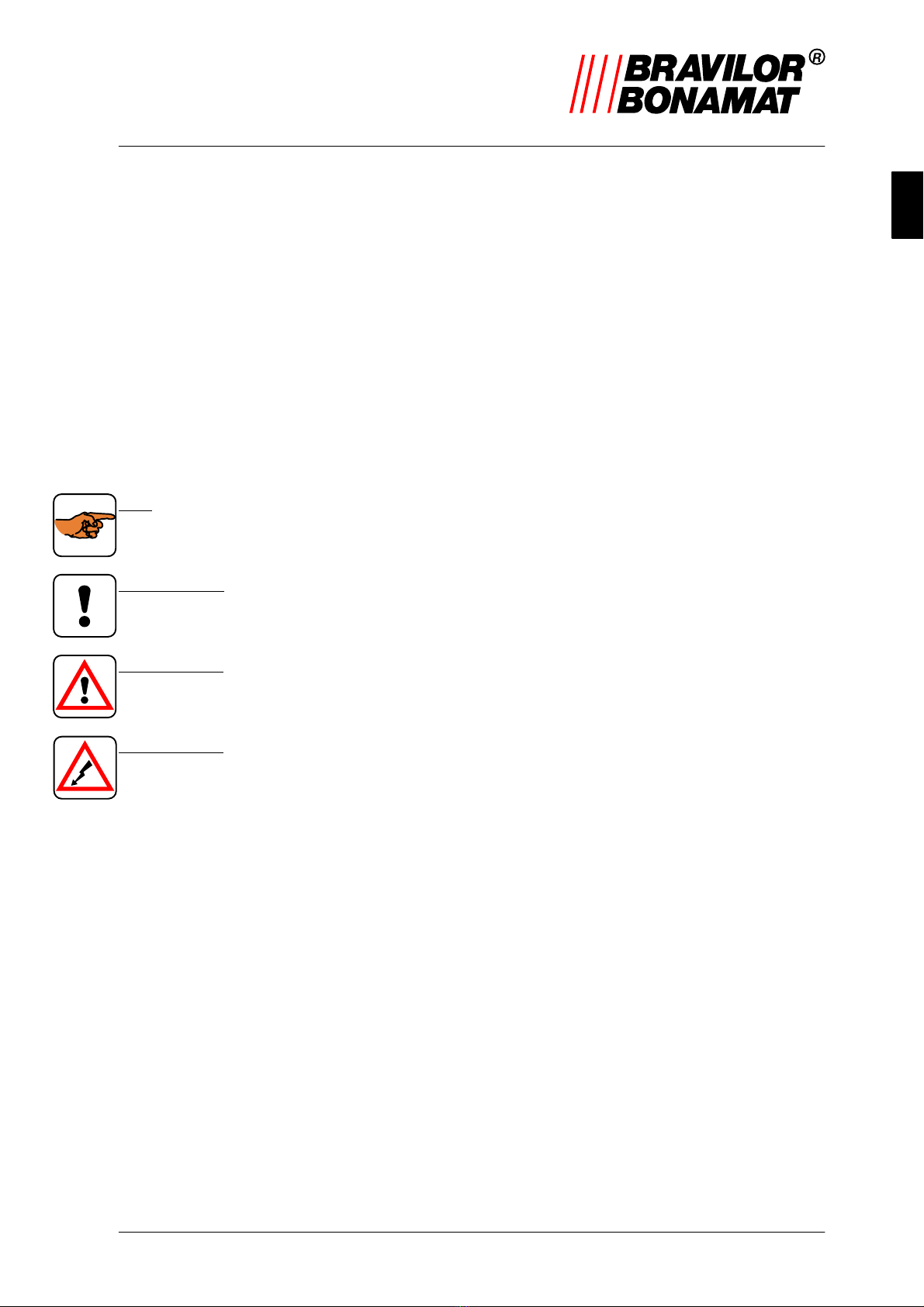
Pictograms and symbols I. . . . . . . . . . . . . . . . . . . . . . . . . . . . . . . . . . . . . . . . . . . . . . . . . . . . . .
Related documents I. . . . . . . . . . . . . . . . . . . . . . . . . . . . . . . . . . . . . . . . . . . . . . . . . . . . . . . . . . .
Document code I. . . . . . . . . . . . . . . . . . . . . . . . . . . . . . . . . . . . . . . . . . . . . . . . . . . . . . . . . . . . . .
Service and technical support II. . . . . . . . . . . . . . . . . . . . . . . . . . . . . . . . . . . . . . . . . . . . . . . . . .
Conditions of warranty II. . . . . . . . . . . . . . . . . . . . . . . . . . . . . . . . . . . . . . . . . . . . . . . . . . . . . . . .
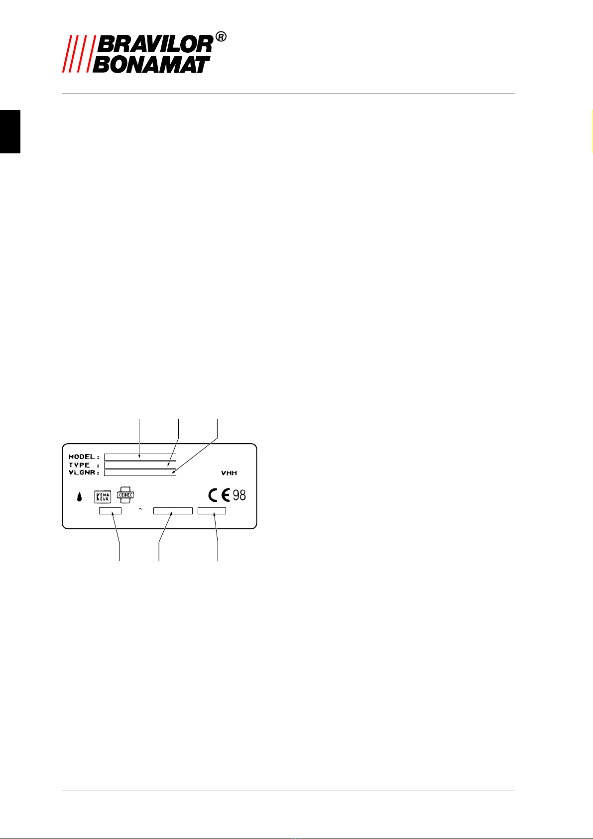
Identification of the device II. . . . . . . . . . . . . . . . . . . . . . . . . . . . . . . . . . . . . . . . . . . . . .
Safety regulations and danger warnings VI. . . . . . . . . . . . . . . . . . . . . . . . . . . . . . . . .
General VI. . . . . . . . . . . . . . . . . . . . . . . . . . . . . . . . . . . . . . . . . . . . . . . . . . . . . . . . . . . . . . . . . . . . .
Operating instructions VI. . . . . . . . . . . . . . . . . . . . . . . . . . . . . . . . . . . . . . . . . . . . . . . . . . . . . . . .
Instructions on the device (if present) VI. . . . . . . . . . . . . . . . . . . . . . . . . . . . . . . . . . . . . . . . . . .
Maintenance VI. . . . . . . . . . . . . . . . . . . . . . . . . . . . . . . . . . . . . . . . . . . . . . . . . . . . . . . . . . . . . . . .
Usage in accordance with purpose VI. . . . . . . . . . . . . . . . . . . . . . . . . . . . . . . . . . . . . . . . . . . . .
Technical specifications VI. . . . . . . . . . . . . . . . . . . . . . . . . . . . . . . . . . . . . . . . . . . . . . . . . . . . . . .
Modifications VI. . . . . . . . . . . . . . . . . . . . . . . . . . . . . . . . . . . . . . . . . . . . . . . . . . . . . . . . . . . . . . . .
Installation VII. . . . . . . . . . . . . . . . . . . . . . . . . . . . . . . . . . . . . . . . . . . . . . . . . . . . . . . . . . . . . . . . . .
Usage VII. . . . . . . . . . . . . . . . . . . . . . . . . . . . . . . . . . . . . . . . . . . . . . . . . . . . . . . . . . . . . . . . . . . . . .
Maintenance and correcting malfunctions VIII. . . . . . . . . . . . . . . . . . . . . . . . . . . . . . . . . . . . . . .
Safety precautions VIII. . . . . . . . . . . . . . . . . . . . . . . . . . . . . . . . . . . . . . . . . . . . . . . . . . . . . . . . . . .
Equipment and the environment VIII. . . . . . . . . . . . . . . . . . . . . . . . . . . . . . . . . . . . . . . . .
Packaging materials VIII. . . . . . . . . . . . . . . . . . . . . . . . . . . . . . . . . . . . . . . . . . . . . . . . . . . . . . . . . .
Scrapping the device VIII. . . . . . . . . . . . . . . . . . . . . . . . . . . . . . . . . . . . . . . . . . . . . . . . . . . . . . . . .
1. Introduction 1. . . . . . . . . . . . . . . . . . . . . . . . . . . . . . . . . . . . . . . . . . . . . . . . . . . . .
1.1 A brief overview of the device 1. . . . . . . . . . . . . . . . . . . . . . . . . . . . . . . . . . . . .
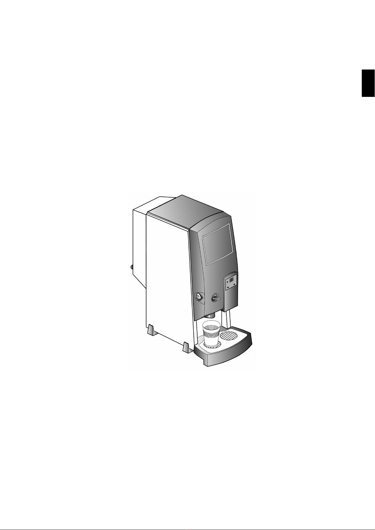
1.1.1 General description 1. . . . . . . . . . . . . . . . . . . . . . . . . . . . . . . . . . . . . . . . . . . . . . . . .
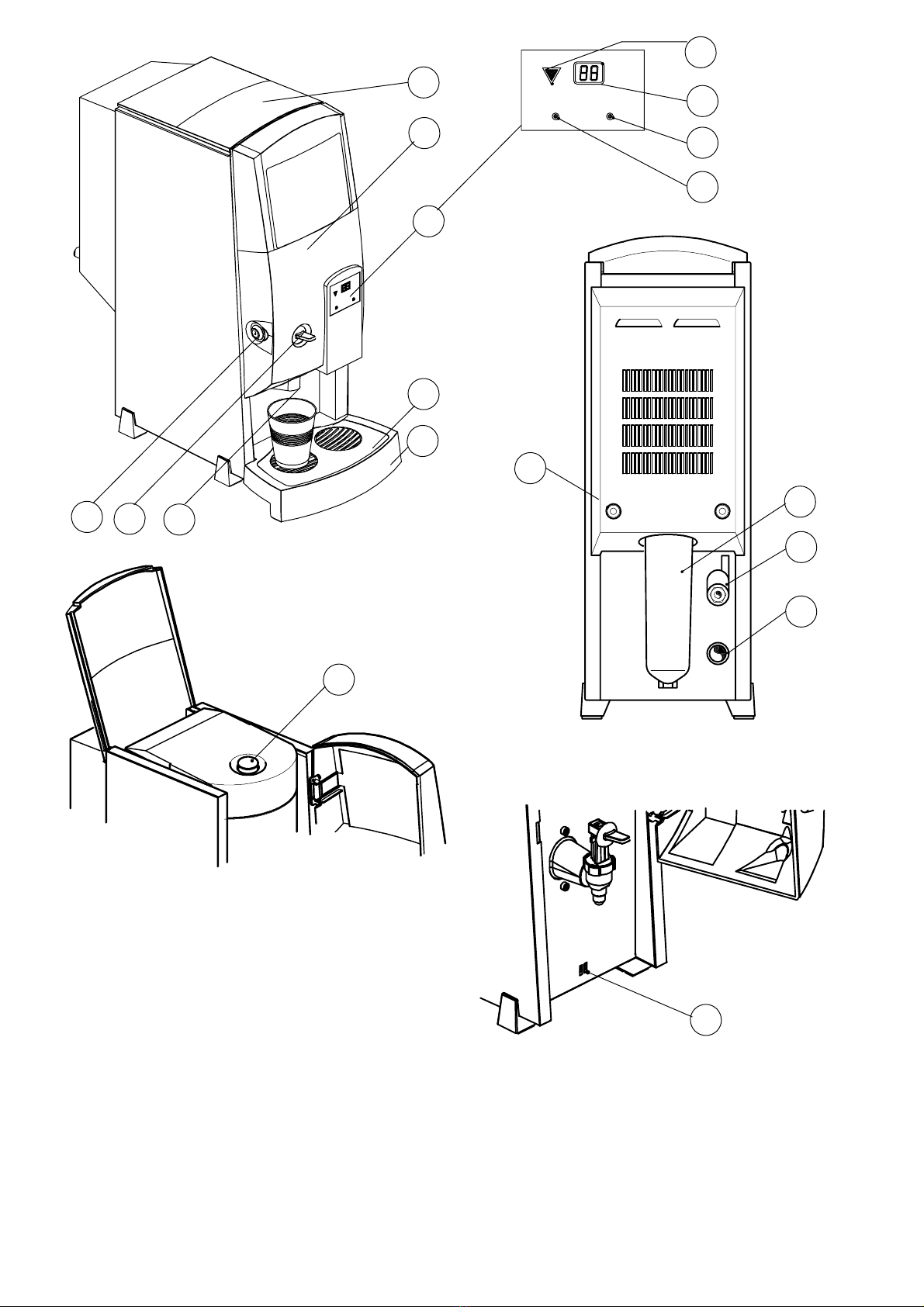
1.1.2 Main components 1. . . . . . . . . . . . . . . . . . . . . . . . . . . . . . . . . . . . . . . . . . . . . . . . . . .
1.2 Summary of operations 1. . . . . . . . . . . . . . . . . . . . . . . . . . . . . . . . . . . . . . . . . . .
1.2.1 Cold–water system 1. . . . . . . . . . . . . . . . . . . . . . . . . . . . . . . . . . . . . . . . . . . . . . . . . .
2. Technical data 2. . . . . . . . . . . . . . . . . . . . . . . . . . . . . . . . . . . . . . . . . . . . . . . . . . .
2.1 General 2. . . . . . . . . . . . . . . . . . . . . . . . . . . . . . . . . . . . . . . . . . . . . . . . . . . . . . . . . .
2.2 Transport dimensions and weights 2. . . . . . . . . . . . . . . . . . . . . . . . . . . . . . . . .
2.3 Dimensions 2. . . . . . . . . . . . . . . . . . . . . . . . . . . . . . . . . . . . . . . . . . . . . . . . . . . . . .
2.4 Electrical system 2. . . . . . . . . . . . . . . . . . . . . . . . . . . . . . . . . . . . . . . . . . . . . . . . .
2.5 Water system 2. . . . . . . . . . . . . . . . . . . . . . . . . . . . . . . . . . . . . . . . . . . . . . . . . . . . .
2.6 Environmental conditions 2. . . . . . . . . . . . . . . . . . . . . . . . . . . . . . . . . . . . . . . . .
2.7 Recommended cleaning fluids and liquid disinfectants 2. . . . . . . . . . . . . .

Table of contents
GB
version 1.0 ECopyright Bravilor Bonamat B.V.
IV
3. Installation 3. . . . . . . . . . . . . . . . . . . . . . . . . . . . . . . . . . . . . . . . . . . . . . . . . . . . . .
3.1 Unpacking 3. . . . . . . . . . . . . . . . . . . . . . . . . . . . . . . . . . . . . . . . . . . . . . . . . . . . . . . .
3.2 Installation 3. . . . . . . . . . . . . . . . . . . . . . . . . . . . . . . . . . . . . . . . . . . . . . . . . . . . . . .
3.2.1 Connection to the water mains (drinking water) 3. . . . . . . . . . . . . . . . . . . . . . . . .
3.2.2 Connection to the electricity supply 3. . . . . . . . . . . . . . . . . . . . . . . . . . . . . . . . . . . .
3.2.3 Connecting the drip–tray to the drain (optional) 4. . . . . . . . . . . . . . . . . . . . . . . . . .
3.2.4 Using the device the first time 4. . . . . . . . . . . . . . . . . . . . . . . . . . . . . . . . . . . . . . . .
4. Everyday usage 5. . . . . . . . . . . . . . . . . . . . . . . . . . . . . . . . . . . . . . . . . . . . . . . . .
4.1 Signalling and display 5. . . . . . . . . . . . . . . . . . . . . . . . . . . . . . . . . . . . . . . . . . . . .
4.2 Operation 5. . . . . . . . . . . . . . . . . . . . . . . . . . . . . . . . . . . . . . . . . . . . . . . . . . . . . . . .
4.2.1 Drawing off cold water 5. . . . . . . . . . . . . . . . . . . . . . . . . . . . . . . . . . . . . . . . . . . . . . .
5. Maintenance by personnel with the appropriate authorisation 7. . . . . .
5.1 General information on cleaning 7. . . . . . . . . . . . . . . . . . . . . . . . . . . . . . . . . . .
5.2 Flushing the cold–water system 7. . . . . . . . . . . . . . . . . . . . . . . . . . . . . . . . . . .
5.3 Cleaning the cold–water reservoir 7. . . . . . . . . . . . . . . . . . . . . . . . . . . . . . . . .
5.3.1 Cleaning procedure for the cold–water reservoir 7. . . . . . . . . . . . . . . . . . . . . . . . .
5.3.2 Replacing the water filter 8. . . . . . . . . . . . . . . . . . . . . . . . . . . . . . . . . . . . . . . . . . . . .
6. Programming 9. . . . . . . . . . . . . . . . . . . . . . . . . . . . . . . . . . . . . . . . . . . . . . . . . . .
6.1 Programming facilities 9. . . . . . . . . . . . . . . . . . . . . . . . . . . . . . . . . . . . . . . . . . . .
6.1.1 Programming buttons 9. . . . . . . . . . . . . . . . . . . . . . . . . . . . . . . . . . . . . . . . . . . . . . . .
6.1.2 Menus (P1, P2, P3 and P4) 9. . . . . . . . . . . . . . . . . . . . . . . . . . . . . . . . . . . . . . . . . .
6.1.2.1 General procedure 9. . . . . . . . . . . . . . . . . . . . . . . . . . . . . . . . . . . . . . . . . . . . . . . . . .
6.1.2.2 P1 Temperature setting 10. . . . . . . . . . . . . . . . . . . . . . . . . . . . . . . . . . . . . . . . . . . . . .
6.1.2.3 P2 Displaying the number of litres drawn off 10. . . . . . . . . . . . . . . . . . . . . . . . . . . .
6.1.2.4 P3 Filter–replacement status 10. . . . . . . . . . . . . . . . . . . . . . . . . . . . . . . . . . . . . . . . .
6.1.2.5 P4 Display of the number of litres drawn off 10. . . . . . . . . . . . . . . . . . . . . . . . . . . .
7. Correcting malfunctions 11. . . . . . . . . . . . . . . . . . . . . . . . . . . . . . . . . . . . . . . . .
7.1 General 11. . . . . . . . . . . . . . . . . . . . . . . . . . . . . . . . . . . . . . . . . . . . . . . . . . . . . . . . . .
7.2 Display messages and their meaning 12. . . . . . . . . . . . . . . . . . . . . . . . . . . . . .
8. Ordering consumables and accessories 13. . . . . . . . . . . . . . . . . . . . . . . . . .
8.1 Consumables 13. . . . . . . . . . . . . . . . . . . . . . . . . . . . . . . . . . . . . . . . . . . . . . . . . . . . .
8.2 Accessories 13. . . . . . . . . . . . . . . . . . . . . . . . . . . . . . . . . . . . . . . . . . . . . . . . . . . . . .

Table of figures
GB
ECopyright Bravilor Bonamat B.V. V
version 1.0
Fig. 3 Contents of machine identification plate II. . . . . . . . . . . . . . . . . . . . . . . . . . . . . . . . . . . . . . . . . . . .
Fig. 4 Signalling and display 5. . . . . . . . . . . . . . . . . . . . . . . . . . . . . . . . . . . . . . . . . . . . . . . . . . . . . . . . . . .
Fig. 5 Cleaning the cold–water reservoir 6. . . . . . . . . . . . . . . . . . . . . . . . . . . . . . . . . . . . . . . . . . . . . . . . .
Fig. 6 Water filter 8. . . . . . . . . . . . . . . . . . . . . . . . . . . . . . . . . . . . . . . . . . . . . . . . . . . . . . . . . . . . . . . . . . . . .
Fig. 7 Programming buttons 9. . . . . . . . . . . . . . . . . . . . . . . . . . . . . . . . . . . . . . . . . . . . . . . . . . . . . . . . . . .

GB
version 1.0 ECopyright Bravilor Bonamat B.V.
VI
Safety regulations and danger warnings
General
The manufacturer accepts no liability for damage or injury resulting from not (strictly)
observing the safety regulations and instructions contained in this document, or from
negligence during installation, use and maintenance of the device indicated on the front
page of this document and any related accessories.
Please contact your dealer if you think there may be any potential danger.
The user of the device is fully responsible at all times for observing the locally
applicable safety regulations and guidelines.
Operating instructions
DEverybody installing, programming or maintaining the device must be aware of the
contents of these operating instructions and observe these instructions as closely as
possible. Management must give instructions to the personnel with the aid of this
document and take account of all the regulations and directions.
DNever change the sequence of the actions to be taken.
DAlways store this document in the vicinity of the device.
Instructions on the device (if present)
DAny warnings and instructions on the device form part of the safety precautions. They may
not be covered or removed and must always be present and legible throughout the entire
life span of the device. Immediately replace or repair any pictograms, warnings and
instructions that have become illegible or that have been damaged.
Maintenance
DSetting up and maintaining the device, as described in this document, is reserved
exclusively for personnel authorised to perform these tasks.Temporary staff and persons
undergoing training may only use the machine under the supervision and authority of
authorized users.
Usage in accordance with purpose 1
The device was designed solely to dispense cold water. Any other or further use is not in
accordance with the purpose. The manufacturer does not accept any responsibility for
damage or injury resulting from this. The device is in compliance with the applicable
standards and guidelines. Only use the device in perfect technical condition and in
accordance with the purpose described above.
Technical specifications
DThe specifications indicated in this document may not be modified.
Modifications
DIt is not permitted to modify (components of) the device.
1. ”Usage in accordance with purpose”as defined in EN 292–1 is the use for which the technical
product is suitable according to the manufacturer’s information –including the information he
supplies in his sales brochure. In case of doubt, usage implies that which is generally understood
from the construction, execution and function of the product. Usage in accordance with the
purpose also implies observing the instructions in the operating instructions.

GB
ECopyright Bravilor Bonamat B.V. VII
version 1.0
Installation
DThe Chiller will not operate optimally when it is set up in rooms where the ambient
temperature is lower than the temperature of the water supplied to it. It can be assumed
by way of a guideline that the ambient temperature must be above 14 _C.
DAs there is a danger of freezing, never place the Chiller in spaces where the temperature
can drop below 0 _C. Through normal use, there should always remain some water in the
device.
DNever install the Chiller in places where water is sprayed or sprinkled.
DDo not place the device with its back against a heat source (i.e. heaters).
DNever tip the device in any direction, always transport and place it in an upright position.
DNever install the device in front of entries, exits and passageways intended for auxiliary or
emergency services.
DPosition the device on a flat, sufficiently robust base, in the vicinity of a water connection
and an earthed electrical connection.
DOnce the device has been installed in place, you should wait for at least 1 hour before its
first use.
DEnsure that the device is connected to a continuous mains voltage. The control unit is
fitted with a ’counter’that records the effective life of the water filter (no longer than 6
months). This counter is deactivated when the mains voltage is switched off.
DNever connect the device to a water outlet where water is contaminated with bacteria. The
carbon filter is only intended to reduce odours and flavours such as chlorine.
DAllow sufficient space at the front and rear of the device for maintenance repairs. The
device draws in air at the rear; therefore, the ventilation grille at the rear may not be
covered. This also applies to the bottom side; it must be possible to blow out the heated
air from this position.
DConnect the device to the water supply system (drinking water) using an easily accessible
manually operated tap in order that it is easy to shut off the water supply, for example for
cleaning, maintenance or in the event of a disaster.
DConnect the device to the electricity supply in such a way that the connection is easy to
break, for example for cleaning, maintenance or in the event of a disaster.
DEnsure that the device is correctly earthed.
Usage
DInspect the device before use and check it for any damage.
DProtect the device against water or moisture. Do not spray the device so that it becomes
wet and do not submerge it in water.
DKeep the control units free from dirt and grease.
DNever use sharp objects to operate the buttons.
DIf the device is not to be used for a long period of time, break the connection with the
electricity supply, shut off the water supply, drain the cold–water reservoir until it is empty
and remove the filter.

GB
version 1.0 ECopyright Bravilor Bonamat B.V.
VIII
Maintenance and correcting malfunctions
TIP
–This document makes a clear distinction between maintenance activities that may be
conducted by the personnel and repairs and maintenance activities not included in this
document that are always reserved for service engineers.
DObserve the specified maintenance intervals. Overdue maintenance can lead to high
costs for repairs and may nullify any warranty claims.
DDo not conduct any maintenance activities on the device before shutting off the electricity
and water supplies.
DRemain in the vicinity of the device during all maintenance activities.
DAlways wear suitable face protection and safety gloves when working with liquid
disinfectants. Wash your hands after using these materials.
Safety precautions
The device is provided with the following safety precaution by default:
–Overflow protection
The required amount of water is measured using a level–detection system. If the
level–detection system does not detect any water for a relatively long period of time, the
Chiller is switched off and message ”E1”appears in the display.
Equipment and the environment
Packaging materials
The packaging used for the transportation and protection of the device, mainly comprises
the following materials:
–(corrugated) cardboard
–Styropor elements
In general, the packaging can be returned to your dealer when the device has been
installed. If this is not possible, ask your municipality’s sanitation department about where
you can dispose of the materials. You can also dispose of the Styropor elements separately.
Scrapping the device
Often, after consultation, your dealer will take possession of any equipment that you wish to
scrap. If this is not possible, you can also ask your municipality about facilities for recycling
or a means of processing the materials in an environmental–friendly way. All the plastic
components have been clearly coded to this end. The printed circuit board contained in the
device and the components connected to this board are electrical and electronic waste
products. The refrigeration compartment contains refrigerant R134A and may only be
processed by a specialized company.
This refrigerant is what is called an ”HFK”, which is a replacement product for ”CFK”, but is
not harmful to the ozone layer.

GB
version 1.0ECopyright Bravilor Bonamat B.V. 1
1. INTRODUCTION
1.1 A brief overview of the device
1.1.1 General description
The CHILLER–002 is a cold–water device,
specially designed for all who enjoy drinking
a refreshing beaker of cool water. The
device can supply 40 beakers (125 ml) of
chilled water per hour.
The device’s settings are
computercontrolled. To this end, the device
is equipped with two programming buttons
that personnel with the appropriate
authorization can use to adjust the settings
(water temperature and filter–replacement
status) and read off the counter levels or set
(reset) them to zero. Once it has been
programmed in accordance with the specific
criteria and requirements, the device can be
operated simply with the aid of the draw–off
tap located at the front of the device.
1.1.2 Main components
The device comprises the following main
components (see fig.1 ):
A. Top cover
B. Door
C. Control panel
1. Filter–replacement indication
2. Display
3. Programming button ⇑
4. Programming button ⇓
D. Drip–tray cover plate
E. Drip–tray
F. Water outlet
G. Draw–off tap for water
H. Lock
I. Water filter
J. Mains lead with plug
K. Water connection
L. Lug
M. Filling aperture
N. Locating holes for drip–tray
1.2 Summary of operations
The device is connected to the electricity
supply and the water mains (drinking water)
with the aid of the plug (fig. 1 , J) and the
water–connection hose supplied (fig. 1 , K).
An electrically operated tap then regulates
the water supply.
TIP
–The summary presented below assumes
that the device is switched on and still
has the factory settings.
1.2.1 Cold–water system
The device is equipped with a cold–water
system. The required water is chilled by a
cooling system. When the desired
temperature appears in the display (fig. 1 ,
C2) a beaker of chilled water can be
dispensed via the draw–off tap as the device
is equipped with a discharge system.
The cooling system and the temperature
sensor fitted in the device ensure that the
water is maintained at the desired, preset
temperature.
The device is equipped with an automatic
filter–replacement signalling function (fig. 1 ,
C1). This is indicated by means of the red
lamp next to the display. This lamp
continues to flash until the filter is replaced
and the counter is reset to zero.
The operating system makes it possible to
accurately record the volume of water that
has been drawn off. This total level can be
read off via the adjustment program.

GB
version ECopyright Bravilor Bonamat B.V.21.0
2. TECHNICAL DATA
2.1 General
Model : Chill–002
Weight (without water) : 16 kg
2.2 Transport dimensions and weights
Transport dimensions (l x h x w ) : 485 mm x 290 mm x 660 mm
Transport weight : 18,5 kg
2.3 Dimensions
DSee fig. 2 .
2.4 Electrical system
TIP
–See the identification label for correct values.
Supply voltage and Frequency : 230 V~ –50 Hz
: 110 V~ –60 Hz
Total capacity : 130 W (575 W)
Class : 1
2.5 Water system
Min. water pressure (supply) : 50 kPa (0,5 Bar)
Max. water pressure (supply) : 1.000 kPa (10 Bar)
Cold–water reservoir volume : ca. 2 l
Hourly capacity cooling system : approx. 5 l/hour, at a water–supply temperature of 20 °C
2.6 Environmental conditions
The device is suitable for use in a room at temperatures of +14 °C to +32 °C.
If the temperature in the room where the device is installed is lower than +14 °C, it is no
longer possible to chill the water to be dispensed owing to the reduced running time of the unit.
In connection with the above–mentioned incorrect operations, it is not advised to install the
device in rooms where the temperature may fall below 14 °C.
2.7 Recommended cleaning fluids and liquid disinfectants
Cleaning agent for the exterior: normal, non–abrasive or corrosive detergent.
Liquid disinfectants for the cold–water reservoir: HADEX(sodium hypochlorite (NaOCl)).
CAUTION!
–Before use, first read the instructions on the packaging of the cleaning agent.

GB
version 1.0ECopyright Bravilor Bonamat B.V. 3
3. INSTALLATION
3.1 Unpacking
DVerify that the device is complete. The contents of the packaging comprise:
–Chiller
–1 drip–tray + grille
–1 water filter
–1 water–connection hose
–1 funnel
–these operating instructions
DIf components are missing or damaged, please contact your dealer.
3.2 Installation
CAUTION!
–It is not advised to install the device in
rooms where the temperature may fall
below 14 °C.
–Never install the device in front of
entries, exits and passageways intended
for auxiliary or emergency services.
DPosition the device on a flat, sufficiently
robust base, in the vicinity of a water
connection and a continuous earthed
electrical connection. Allow sufficient
space at the front and rear of the device
for maintenance repairs. Install the
drip–tray in front of the device. Place the
fixing cams of the drip–tray in the locating
holes (fig. 1 , O).
3.2.1 Connection to the water
mains (drinking water)
DConnect the device to the water supply
system (drinking water) using an easily
accessible manually operated tap in order
that it is easy to shut off the water supply
in the event of a disaster.
3.2.2 Connection to the
electricity supply
WARNING
nSupply voltages may differ from one
country to the next. Please ensure that
the device is suitable for connection to
your local network. The identification
label contains data relating to supply
voltage and frequency.
DConnect the device to the electricity
supply to ensure a continuous supply of
electricity. This maintains the operation of
the cooling system and the water filter’s
(six–monthly) counter remains active.
DEnsure that the device is correctly
earthed.

GB
version ECopyright Bravilor Bonamat B.V.41.0
3.2.3 Connecting the drip–tray
to the drain (optional)
DConnect the drip–tray (fig. 1 , E) to the
drain with the aid of a drainage pipe. Drill
a hole through the drainage spout at the
rear of the drip–tray. It is easy to cut the
drainage pipe to the desired length and
then slide this over the drainage spout of
the drip–tray.
CAUTION!
–Ensure that the drainage pipe lies flat.
3.2.4 Using the device the first
time
CAUTION!
–Inspect the device before use and verify
that it is not damaged.
–Once the device has been installed in
place, you should wait for at least 1 hour
before its first use.
TIP
–The first time the device is used, it makes
use of the default factory settings. At a
later date, authorized personnel can
change these settings if required. See
Chapter 6. for information on this.
–The first time the device is used, it takes
approx. 30 minutes before the water has
reached the desired temperature.
DActivate the device by putting the plug into
the socket. The red triangle (fig. 1 , C1)
and the display (fig. 1 , C2) briefly light up.
The display then shows the temperature.
The display continues to flash until the set
temperature + 4 °C is reached.
DWait approx. 10 minutes until the reservoir
has filled.
DDeactivate the device by removing the
plug from the socket.
DUse the draw–off tap (fig. 1 , G) to draw
off approx. 2 litres of water and throw this
away.
DActivate the device again by putting the
plug into the socket.
DWait approx. 30 minutes until the display
shows the preset temperature of 6 °C.
DThe device is then ready for use, see
Chapter 4.
DNow only remove the plug from the socket
f or maintenance repairs.

GB
version 1.0ECopyright Bravilor Bonamat B.V. 5
4. EVERYDAY USAGE
During use, the default factory setting may
not be considered to be correct or adequate
for the situation in which the device is being
used. These settings can be adjusted –by
personnel with the appropriate
authorization–in accordance with the
instructions in Chapter 6.
Consequently, the present chapter (4.) only
describes normal, everyday use of the
device by any user.
Periodic maintenance activities for personnel
with the appropriate authorization are
described in Chapter 5.
4.1 Signalling and display
The following data can be read off the device
during operations:
C1
C2
C3
C4
Fig. 4 Signalling and display
1. Display (C2)showing the set
temperature.
2. Filter–replacement signalling (C1)
The red triangle lights up and flashes to
indicate that the filter must be replaced.
The filter–replacement procedure (to be
conducted only by personnel with the
appropriate authorization) is described in
Section 5.3.2.
4.2 Operation
CAUTION!
–Ensure that the control buttons are kept
free from dirt and grease.
–If the device is not to be used for a long
period of time, break the connection with
the electricity supply, shut off the water
supply, remove the filter and throw it
away.
4.2.1 Drawing off cold water
DThe display flashes when the water has
not yet reached the set temperature. Wait
until the display is no longer flashing.
DPlace a beaker under the cold–water
outlet (fig. 1 , F) and draw off a refreshing
beaker of cold water.

GB
version ECopyright Bravilor Bonamat B.V.61.0
B
C
A
D
E
Fig. 5 Cleaning the cold–water reservoir

GB
version 1.0ECopyright Bravilor Bonamat B.V. 7
5. MAINTENANCE BY PERSONNEL WITH
THE APPROPRIATE AUTHORISATION
5.1 General information on cleaning
DClean the exterior of the device with a
damp cloth (possible with a non–abrasive
cleaning agent).
DUse a vacuum Cleaner to clean the grille
at the rear of the device.
WARNING
nDo not spray the device so that it
becomes wet and never submerge it in
water.
5.2 Flushing the cold–water system
Flush the cold–water system with clean
water if you have not used it to draw off
water for one to two weeks:
1. Deactivate the device by removing the
plug from the socket.
2. Use the draw–off tap to draw off the
contents (approx. 2 litres) of the
cold–water reservoir.
3. Reactivate the device by putting the plug
into the socket.
4. Now wait approx. 30 minutes until the
display stops flashing and the water is
again at the set temperature.
The device is now ready for use.
5.3 Cleaning the cold–water reservoir
The cold–water reservoir must be cleaned:
–when the device has not been used for a
relatively long period of time and the
water that is drawn off has an unusual
taste.
–when the water filter has been replaced,
but the water that is drawn off still has an
unusual taste.
WARNING
nRemain in the vicinity of the device
during the cleaning procedure.
5.3.1 Cleaning procedure for
the cold–water reservoir
DSee fig.5 .
WARNING
nBefore use, first read the instructions for
using the drinking water disinfectant. For
example Hadex(sodium hypochlorite).
nWear suitable face protection and safety
gloves when working with the disinfectant.
1. Dissolve a liquid disinfectant (fig.5 B), for
example sodium hypochlorite, in approx.
2 litres water (fig.5 A). Use a clean
measuring jug for this!
2. Stir this briefly.
3. Deactivate the device by removing the
plug from the socket.
4. Draw off all the contents of the cold–water
reservoir.
5. Use the key to open the hatch (fig.1 H)
and fold back the lid (fig.1 A).
6. Use the funnel (fig.5 E) to pour the
sodium hypochlorite solution (fig.5 D) into
the water inlet.
7. Allow this to stand for approx. half an hour.
8. Empty the cold–water reservoir entirely
(approx. 2 litres) via the draw–off tap
(fig.1 G).
9. Now pour in 2 litres of clean water into
the reservoir and draw this off.
10. Repeat this two or three times in
succession.

GB
version ECopyright Bravilor Bonamat B.V.81.0
11. Close the lid (fig.1 A), use the key
(fig.1 H) to close the hatch and reactivate
the device by putting the plug into the
socket.
12. Now wait approx. 30 minutes until the
display stops flashing and the water is
again at the set temperature.
The device is now ready for use.
TIP
–If the water filter has not been replaced
for six months, it is advisable to do so
immediately after this cleaning
procedure. See Section 5.3.2 for
information on replacing the filter.
A
B
C
D
Fig. 6 Water filter
5.3.2 Replacing the water filter
When the filter–replacement indicator
(fig.1 C1) flashes, the water filter at the rear
of the device (fig.1 I) must be replaced (fig.6 ):
1. Place the new filter in a convenient
position.
2. Record the current date on the enclosed
sticker and affix this to the new water filter.
3. Deactivate the device by removing the
plug from the socket.
4. Use the draw–off tap (fig.1 G) to empty
the cold–water reservoir entirely (approx.
2 litres).
5. Turn the device through 90°(if possible)
in order that the filter is more easily
accessible.
6. Rotate the filter to be replaced through
90°in a clockwise direction (fig.6 C).
7. Use a little force to pull the filter
downward, causing it to be released.
8. Remove the filter and throw it away.
9. Hold the new filter in such a way that the
fixing cams (fig.6 D) are pointing towards
the sides of the device.
10. Position the filter directly beneath the
filter connections (fig.6 A) and use a little
force to push it upward so that the fixing
cams (fig.6 D) are touching the edge on
the filter connection.
11. Now rotate the filter in an anticlockwise
(fig.6 B) direction until it can be turned no
further, thereby locking the filter in place.
12. Put the plug into the socket. Wait for 10
minutes, then remove the plug from the
socket again. Draw off the entire contents
of the reservoir (approx. 2 litres). Throw
this away.
13. Reactivate the device by putting the plug
into the socket.
14. Always reset the counter for the
filter–replacement indicator to zero after
replacing the water filter, this is as follows:
14.1 Press both programming buttons
(fig.1 , C3 and C4) and keep them
pressed in (approx. 5 seconds) until
the filter–replacement indicator
(fig.1 C1) lights up.
14.2 Now release both buttons.
14.3 Within two second, press the
left–hand button (fig.1 C4) and keep
this button pressed in for approx. 5
seconds until the indicator lamp
(fig.1 C1) is extinguished. The
counter has now been reset to zero.
14.4 Now wait approx. 30 minutes until
the display stops flashing and the
water is again at the set temperature.
The device is now ready for use.
TIP
–Ensure that there is always at least one
spare water filter in stock.
CAUTION!
–The remaining maintenance activities are
strictly reserved for specially trained
service engineers for cold–water systems.
Table of contents
Other BRAVILOR BONAMAT Water Dispenser manuals
Popular Water Dispenser manuals by other brands

Forbes
Forbes XTRA TUFF user guide

Spectrum
Spectrum SWS Simplex Installation, service & operation manual

Nephros
Nephros HydraGuard 10" UltraFilter - Flush Instructions for use

Aquion
Aquion Oxydizer Technical manual

Morton
Morton M45 Installation and operation manual

GE
GE GXSF30H Owner's manual and installation instructions

ECOPERLA
ECOPERLA VITA 12 user manual

Water Right
Water Right ISP1-1044 Installation instructions & owner's manual

Hidro-Water
Hidro-Water KOBE WS1CI UF User& installer's manual

H2O LIFE SOURCE
H2O LIFE SOURCE EcoSmart user manual

ClearStream
ClearStream 500DAST manual

Aqua Cooler
Aqua Cooler ODYSSEY Series Usage and Care Manual