SMC Networks ASR Series User manual
Other SMC Networks Control Unit manuals
SMC Networks
SMC Networks VM100-A Series User manual
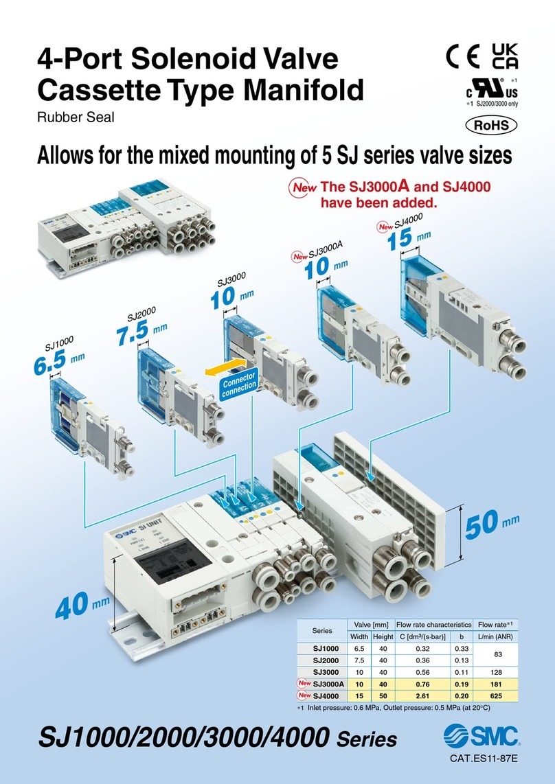
SMC Networks
SMC Networks SJ3000A User manual

SMC Networks
SMC Networks VP4 Series User manual
SMC Networks
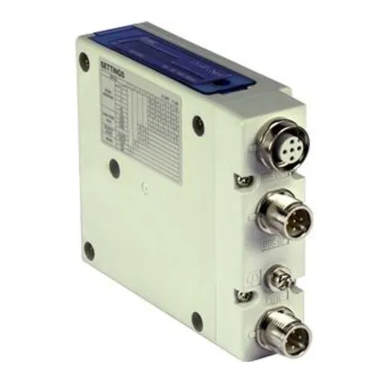
SMC Networks EX260-SEC1 User manual
SMC Networks
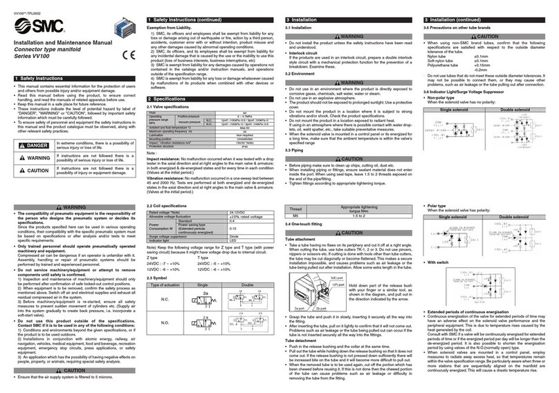
SMC Networks VV100 Series Manual
SMC Networks
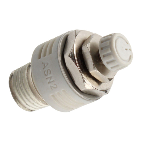
SMC Networks ASN2 Series User manual
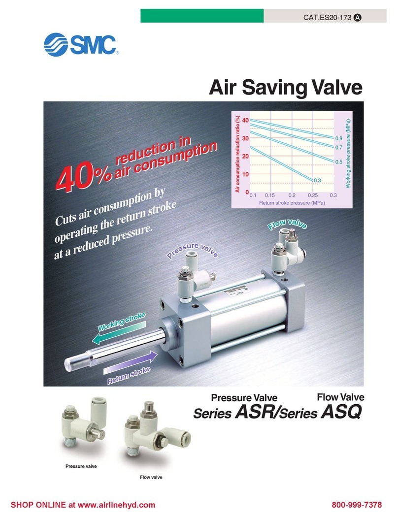
SMC Networks
SMC Networks ASR Series User manual

SMC Networks
SMC Networks XGTP31-50336 Series User manual
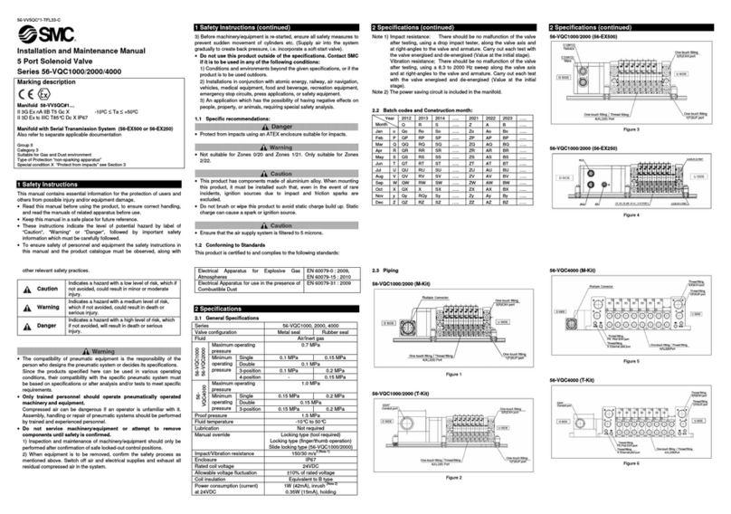
SMC Networks
SMC Networks 56-VQC1000 Series Manual
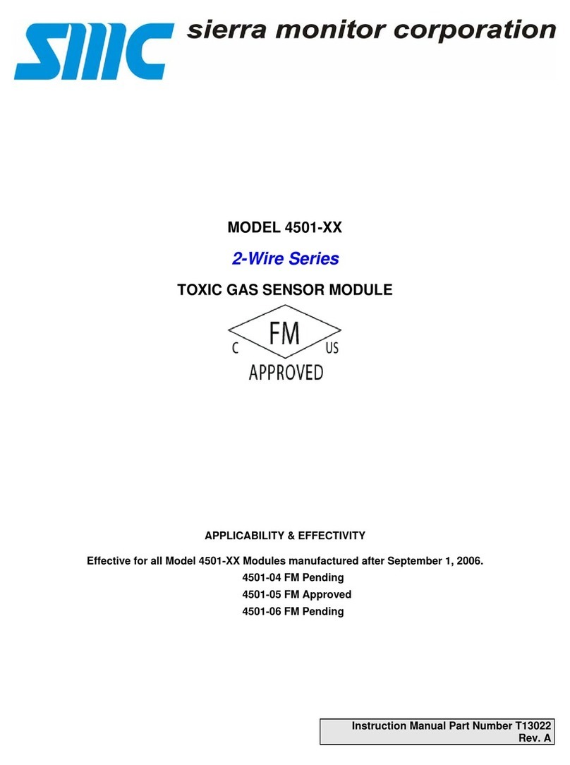
SMC Networks
SMC Networks 4501 Series User manual
SMC Networks
SMC Networks TigerSwitch series User manual

SMC Networks
SMC Networks VR51 Manual
SMC Networks
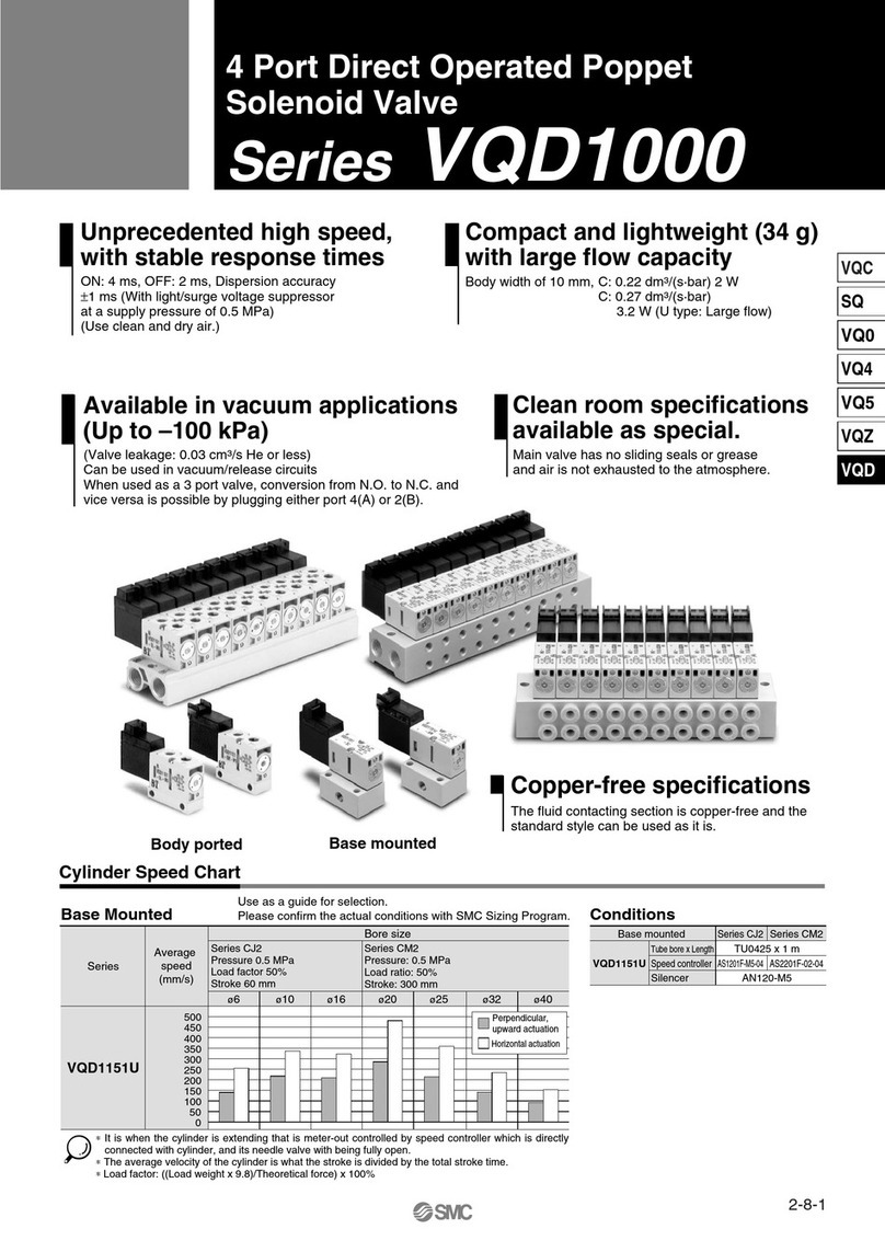
SMC Networks VQD1000 Series User manual
SMC Networks
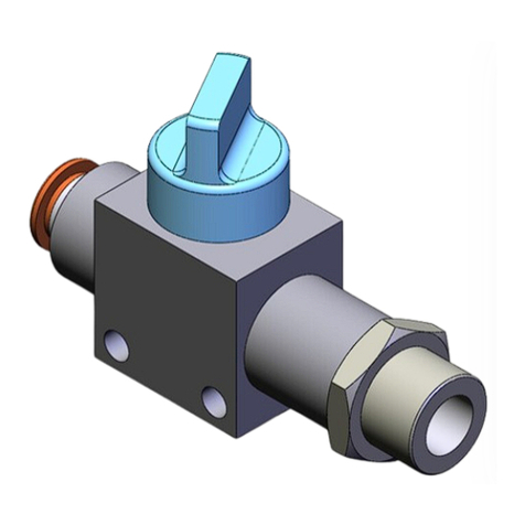
SMC Networks VHK-A User manual
SMC Networks
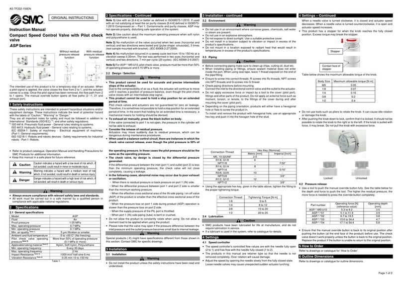
SMC Networks ASP Series User manual
SMC Networks
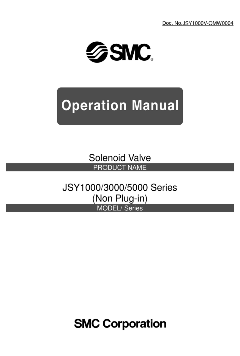
SMC Networks JSY1000 Series User manual
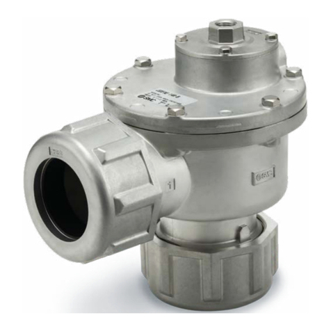
SMC Networks
SMC Networks JSXFA Series User manual
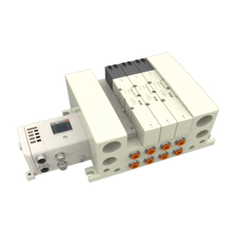
SMC Networks
SMC Networks VQC4000 User manual
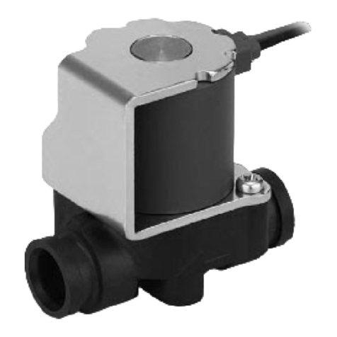
SMC Networks
SMC Networks VDW30-XF Series Owner's manual
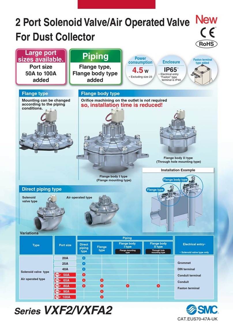
SMC Networks
SMC Networks VXF2 Series User manual
Popular Control Unit manuals by other brands

Festo
Festo Compact Performance CP-FB6-E Brief description

Elo TouchSystems
Elo TouchSystems DMS-SA19P-EXTME Quick installation guide

JS Automation
JS Automation MPC3034A user manual

JAUDT
JAUDT SW GII 6406 Series Translation of the original operating instructions

Spektrum
Spektrum Air Module System manual

BOC Edwards
BOC Edwards Q Series instruction manual

KHADAS
KHADAS BT Magic quick start

Etherma
Etherma eNEXHO-IL Assembly and operating instructions

PMFoundations
PMFoundations Attenuverter Assembly guide

GEA
GEA VARIVENT Operating instruction

Walther Systemtechnik
Walther Systemtechnik VMS-05 Assembly instructions

Altronix
Altronix LINQ8PD Installation and programming manual
