Brecknell SBI-505 User manual

1
SBI-505 Indicator
User Instructions
AWT35-500827
Rev. A1

2
1.1 Contents
Introduction on page 3
Installation on page 5
Basic Operation on page 7
If you choose clr n, the indicator exits the accumulation mode without clearing
the total weight. If you choose clr y, the total weight is cleared and the indicator
exits accumulation mode. on page 10
Calibration and Parameter Setting on page 11
Output Format on page 19
Troubleshooting and Maintenance on page 22

3
1.2 Introduction
For safe operation please read and follow all safety information and
instructions.
This indicator is designed for basic weighing function. This includes:
lZero
lTare
lGross weight
lNet weight
lAccumulation
lPrinting
lAnimal weighing
Both kg and lb units of measure are available.
The default print format contains the following information:
lS.N. (serial number)
lGross weight
lNet weight
lTare weight
lDate
lTime
1.2.1 Options:
lPrinter
lRS232 serial interface or second display (remote)
WARNING: Settings, calibration, inspection and
maintenance should only be done by trained personnel.
WARNING: This indicator is a static sensitive device.
Remove power before making any electrical
connections. Do not touch any internal components.
Please take all anti-static precautions.

4
1.2.2 Specifications:
Accuracy class: 6000 e
Resolution display: 30, 000
ADC: 2,000,000
Zero stability error: TK 0< 0.1μV//K
Span stability error: TK spn< ± 6 ppm//K
Sensitivity (internal): 0. 3V /d input voltage -30 ~ 30μmV DC
Input voltage: 9-13.8 VDC: 0.3 amps (center terminal positive)
Excitation circuit: 5 VDC, 4 wire connection
maximum of 6 - 350Ω load cells
AC power adapter: AC100/240V: 50-60Hz, 1.6 amp
center positive 9 [email protected] amps
Maximum power source: 12VDC
Operation temperature: - 10 °C ~ + 40 °C
Operation humidity: ≤90%RH
Storage temperature: - 40 °C ~ + 70 °C
5
1.3 Installation
1.3.1 Power Supply Connection
The indicator is powered by an A/C adapter that plugs directly into the DC pin
at the bottom of the indicator. The indicator accepts 9 - 12 VDC center positive
adapter.
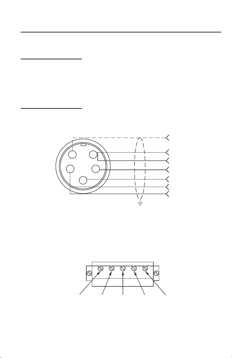
1.3.2 Connection of Loadcell and Indicator
The indicator can be connected up to 6 - 350Ω load cells. 4 wire or 6 wire
loadcells are acceptable.
Figure 1.1 Quick Disconnect
If using interface cable p/n AWT05-505848 (optional):
red = + exc., green = +sig, white = -sig, black = -exc.
Figure 1.2 PC Board Connection
51
42
3
HD
+Exc
+Sen
+Sig
-Sig
-Exc
-Sen
+SIG GND+EXC -EXC-SIG
6
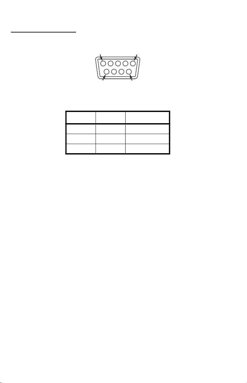
1.3.3 Communication interface
Below is the RS232 DB9 pin:
Pin assignments are shown below:
DB9 joint Definition Function
2 TXD Sending data
3 RXD Receiving data
5 GND Ground interface
1
9
99
5

7
1.4 Basic Operation
1.4.1 Power
Press and hold the ON/OFF key, shown below, for two seconds to power on or
off the indicator. After a self-test, normal weighing mode will be accessed.
1.4.2 Zero Operation
Initial Zero Setting During power up, if the weight on the scale is
within the initial zero tolerance, the indicator will
show zero automatically. The center of zero and
stable annunciators will be lit.
Pushbutton Zero When the scale is stable and not showing a
negative weight, you can zero the weight, within
tolerance, by pressing the Zero key, shown
below.
1.4.3 Tare Operation
When a gross weight is tared, the indicator will show the net weight. The Net
and Tare annunciators will light.
In tare mode, press the Tare key to clear the tare weight and the indicator will
show the gross weight.
1.4.4 Print
If the weight is stable, press the Print key to print the weight to a connected
printer.
ON
OFF
Zero

8
1.5 Counting Function
Follow these steps to count items of the same weight.
1.5.1 Getting a Piece Weight
1. While in the weighing mode, press the Zero key to clear weight from the
scale.
2. Load pre-counted sample pieces of (5, 10, 20, 50, 100, 200, or 500) on
the scale and press the Count key.
PCS 0 is displayed.
3. Using the Zero key, select from the quantity choices (5, 10, 20, 50,
100, 200, 500).
4. Press the Print key to select the displayed choice.
The quantity of items is shown.
5. Remove the sample pieces and zero the scale if necessary.
6. Load the items to be counted on the scale.
The quantity of items is shown.
7. Press the Count key to return to weighing mode.
If you want to weigh items with a different piece weight you must turn the unit
off and on again and then repeat steps 1 through 7.

9
1.6 Accumulation Operation
1. With 0 on the display, add the weight to the scale. Press the Total key
to enter the accumulation mode.
The Total annunciator turns on and the display shows n 001,
and then the display goes back to the loaded weight.
2. Unload the weight.
The display shows 0.
3. Load the second weight and press the Total key.
n 002 is displayed then the display goes back to the loaded
weight.
4. Repeat the previous steps for a maximum 999 times.
Viewing the Accumulation
1. To view the values during accumulation, press and hold Total and ON/
OFF keys.
nnn is displayed and then the total accumulated weight is
displayed. nnn is the number of accumulations included in the
total weight.
2. If the total weight is beyond the display capability, it will show the first
4 digits then the last 4 digits. For example, the first four digits are 0012
and the last 4 digits are 34.56, the actual weight is 1234.56.
Clearing the Accumulated Weight
Follow these steps to exit the accumulation function:
1. While the display shows the last 4 digits of the accumulated weight,
press and hold the Total key.
clr n is displayed. This prompt means Clear the accumulated
weight? - No.
2. Press Zero or Tare to toggle between clr n and clr y which means
Clear accumulated weight? - Yes.

10
3. When the desired choice is displayed, press the Print key to accept
that choice.
If you choose clr n, the indicator exits the accumulation mode
without clearing the total weight. If you choose clr y, the total
weight is cleared and the indicator exits accumulation mode.
11
1.7 Calibration and Parameter Setting
The Parameter menu is divided into a calibration section and a parameter
configuration section. To enter the parameter part of the menu, follow step 1
below. To enter the calibration plus the parameter section, follow step 2 below.
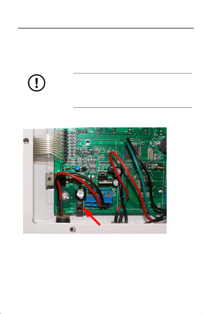
You may need access to the Seal switch on the main board, shown in the photo
below.
1. For access to the parameter section only, the Seal switch must be in the
OFF position. Press and hold the Print and Total keys.
This accesses the menu section numbered C08-C39.
2. For access to both the calibration and parameter sections, the Seal
switch must be in the ON position. Press and hold the Print and Total
keys.
This accesses the complete menu numbered C01-C39.
CAUTION: If you break the official seal to open
the back of the indicator you may need to have
the indicator recertified by local weights and
measures officials. Open the back only if you are
sure it is correct to do so.
Seal switch
12
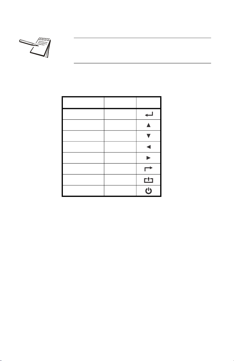
The table below shows the name and symbol of each front panel key and their
function while in the menu.
Be sure to return the seal switch to its original setting
once you are finished with calibration and
configuration.
Function Key Symbol
Enter Print
Increase Zero
Decrease Tare
Left kg/lb
Right Gross
Back Total
Exit Calibration Count
Power ON/OFF

13
1.7.1 Calibration Instructions
When initial installation or recalibration are necessary, locate the seal switch
and place it in the ON position.
Follow the calibration steps. Press and hold the Print and Total keys to access
the calibration menu. Below are the seven calibration parameters.
The SBI-505 requires a minimum of 10% of the
configured scale capacity in dead weight to calibrate
the indicator.
Step Method of Operation Display Remark
1[C01 ] After you enter calibration mode, it displays
[C01 ] (1 is blinking)
2
press
press or to toggle
choices
[C01 X] Calibration Weight option:
X=1=kg
X=2=lb
3
press
press
press or
[C02 ]
[C02 0]
[C02 2]
Set decimal position (2 is blinking)
Option: 0/1/2/3/4
Select decimal digit
example: two decimal places [C02 2]
4
press
press
press or
[C03 ]
[C03 1]
Set graduation (3 is blinking)
Option:1/2/5/10/20/50
Select required graduation
Example: graduation 5 = [C03 5]
5
press
press
press or /
[C04 ]
[XXXXXX]
Max capacity (4 is blinking)
Current setting shown (default 10000)
Example: max weighing 100kg = [0100.00]
6
press
press
press or
press
[C05 ]
[C05 0]
[C05 1]
[CAL 9]
[0000.00]
Zero calibration options (5 is blinking)
0=skip zero calibration (default)
1=zero calibration. Choose 1 and ensure
scale is empty, then press . Wait till
display counts down to [0.00] (example for
two decimal point). At 0 the zero calibration is
complete.

14
1.7.2 Reset Configuration Parameters to Defaults
To reset the indicator to its default configuration the Cal switch must be in the
"ON" position.
7
press
press
press or
press
press or /
press
[C06 ]
[C06 0]
[C06 1]
[SPAN ]
[0100.00]
[0800.00]
[CAL 9]
[0800.00]
[CAL End]
Span calibration options (6 is blinking)
0= No span calibration
1= Span calibration
Load weights on scales to 100% of capacity.
Suggest close to the max capacity, at least
10% of max.capacity. Suggested minimum
span weight is 10% of capacity.
Enter actual weight applied. Example shown
is 800.00. Press press and countdown
begins. CAL End is displayed then 0800.00
when cal is complete.
Press Count to exit calibration. Press Print to
proceed to Parameter C07.
Method of Operation Display Remark
press
press
press or
[C07 ]
[C07 0]
[C07 1]
Default parameters setting option
0=skip default parameters
1=restore default parameters
Note: after the above parameters setting is
finished, please do not select 1 to avoid losing
new setting of parameters.
Step Method of Operation Display Remark

15
1.7.3 Application Function Parameters Setting
Chart
From step 1 on page 11, parameter C08 will be displayed. Press or to find
the parameter to be changed. See the table below for information on available
parameters.
Function Parameter Parameters Setting and Instruction
Key tone C08
Warning tone
Options: 0 = no key tone
1 = key tone
Automatic power off C09
Automatic power off
Option: 0= close auto power off
10= power off automatically if no
change within 10 minute.
30= power off automatically if no
change within 30 minute.
60= power off automatically if no
change within 60 minute.
Power saving setting C10
Power saving setting
LED Version ONLY:
Option: 0= continuous power on
3= power off if no scale or
keyboard activity within 3min.
5= power off if no scale or
keyboard activity within 5 min.
LCD Version:
0= power off backlight
1= backlight when the weight
changes or keyboard activity.
2= constant backlight
NA C11 = NA NA
Unit key C12
Kg/lb conversion
C12=0 kg only
C12=1 kg and lb both active
Upper/lower limit alarm
C13
Upper limit alarm
value Can be set to a value within the maximum
capacity limit
C14
Lower limit alarm
value
A/D Counts C15 Raw counts Enter C15 to check A/D counts
16
Date and time C16 Date set the date, from left to right: year/month/
day
C17 Time set the time from left to right: 24hour/min/sec
RS-232
Communication setting
C18
Serial interface data
strings
Output/Input options (Output Format on page
19):
0= Serial interface data output disable
1=Continuous transmit to remote display
2=Print key only
3=Command request method to a host
device. See Troubleshooting and
Maintenance on page 22
4= Indicator sends format continuously to a
computer.
5= Indicator sends format continuously to a
host device compatible with RD65 remote
display from Brecknell.
C19 Baud rate
Baud rate option:
0=1200/1=2400/2=4800/3=9600
Fixed 8,none & 1 stop bit
Zero range
C20
Manually zero range
Baud rate options:
0= Disable zero key
1=±1% max capacity
2=±2% max capacity
4=±4% max capacity
10=±10% max capacity
20=±20% max capacity
100=±100% max capacity
C21
Initial zero range
Option:
0= Disables initial zero setting on power up
1=±1% max capacity
2=±1% max capacity
5=±1% max capacity
10=±1% max capacity
20=±1% max capacity
Function Parameter Parameters Setting and Instruction

17
AZT - Automatic Zero
tracking
C22
Automatically zero
tracking range
Options:
0= Disable zero tracking
0.5=±0.5d
1.0=±1.0d
2.0=±2.0d
3.0=±3.0d
4.0=±4.0d
5.0=±5.0d
Note: 1. d = division
2. the zero tracking range cannot
bigger than manual zero range, see
C20.
C23
Automatically zero
tracking time
Options:
0= Disable zero tracking time
1= 1 second
2= 2 seconds
3= 3 seconds
Overload range C24
Overload range
Option:
00= close overload range
01d~99d
remark: d =division
Negative range
C25
Negative display
range
Option:
0=-9d
10=10% max. capacity
20=20% max. capacity
50=50% max. capacity
100=100% max. capacity
Stability C26
Stability time
Option:
0= quick
1= medium
2= slow
C27
Stability range
Option:
1= 1d 2=2d 5=5d 10=10d
D= division
Function Parameter Parameters Setting and Instruction
18
Digital filter
C28
Dynamic filter
Instruction: Dynamic
filter is collecting the
data filter before
loaded weight
stable. When loaded
weight easily
shaking (for
example animal),
you can set this filter
to make weight
display more stable
Option:
0= Disable dynamic filter
1=1 digital filter strength
2=2 digital filter strength
3=3 digital filter strength
4=4 digital filter strength
5=5 digital filter strength
6=6 digital filter strength
Note: Do not over filter. The bigger the
number, the more aggressive the filtering.
Try less than 3.
C29
Noise filter
Option:
0=Disable noise filter
1=1 digital filter strength
2=2 digital filter strength
3=3 digital filter strength
C30
Print time and date
C30=0 yy.mm.dd
C30=1 mm.dd.yy
C30=2 dd.mm.yy
C30=3 yy.mm.dd
NA C31 NA NA
NA C32 NA NA
NA C33 NA NA
NA C34 NA NA
NA C35 NA NA
Gravity of calibration
location C36 C36=9.7000~9.9999
Gravity of destination
Version No.
C37
C38
C37=9.7000~9.9999
NA C39 NA NA
Function Parameter Parameters Setting and Instruction
19
1.8 Output Format
1.8.1 Option 1 - Not Available
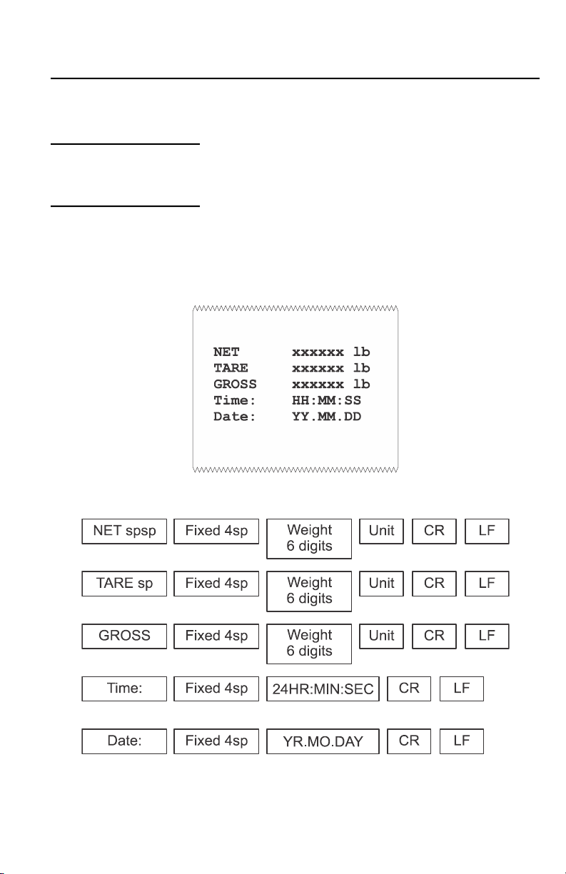
1.8.2 Option 2 - PRINT key only
By default, if you press the Print key while in net weighing mode, the following
format will be sent to a peripheral device. In gross mode the first two lines will
be left out of the format.

20
1.8.3 Option 3 - Host commands
When the indicator receives one of the commands shown in the table below,
the indicator responds with a corresponding format. An example for the R
command is shown below.
Command word and role as follows:
Example: R command receive data format
Print format for R command
NET XXXXXX(unit)
TARE XXXXXX(unit)
GROSS XXXXXX(unit)
Time: 24hr.mn.ss
Date: yy.mm.dd
ASCII
Command NAME Function
T TARE Save and clear tare
Z ZERO Zero gross weight
P PRINT Print the weight when stable
R G.W/N.W Read gross weight or net weight w/motion
C Kg/lb Kg/lb conversion
Start
Transmission
Polarity:
<SP> = Positive
“-” = Negative
Weight Data Space
Units:
lb = pound
kg = kilogram
Space
Gross/Net:
GR = Gross
NT = Net
Line
Feed
Carriage
Return
Fixed
Space
Other manuals for SBI-505
1
Table of contents
Other Brecknell Measuring Instrument manuals

Popular Measuring Instrument manuals by other brands


Chauvin Arnoux
Chauvin Arnoux B102 user manual

Kimans
Kimans HYDRASONIC S8 user manual

SYCLOPE
SYCLOPE HYDRO'pH Installation, commissioning, maintenance and programming instructions

Teledyne Lecroy
Teledyne Lecroy USB Advisor T3 quick start

Inepro
Inepro DZT 6252 Short manual

PRAXSYM
PRAXSYM PM-6000 user manual