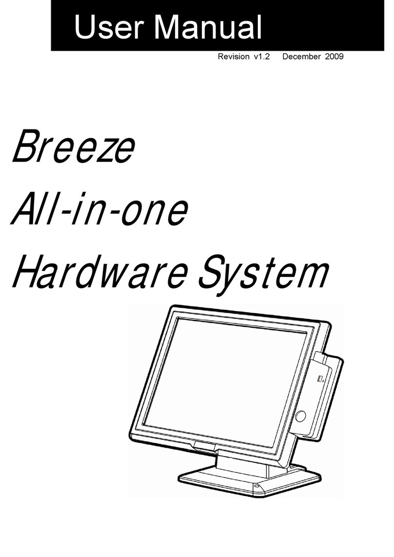
Breeze ECT User manual

..an embedded design lab
1
Breeze Embedded Computing Terminal
User’s Guide

..an embedded design lab
2
Disclaimer
This Manual has been reviewed and validated for accuracy. The descriptions it contains are
accurate for Breeze Embedded Computing Terminal. Breeze Innovation Pvt. Ltd. assumes no
liability for damages incurred directly or indirectly from errors, omissions or discrepancies that
may appear in this manual including the product and the software described in it. It may also
be noted that this Manual is subject to change without notice.
Trademarks
All Trademarks and Brand names appearing in this Manual may or may not be Registered
Trade Marks or Brand names of the respective companies and are used only for identification
and explanation to the benefit of the user.
Doc No: UG04081604

..an embedded design lab
3
Contents
1. INTRODUCTION....................................................................................................................................4
2. INSTALLATION......................................................................................................................................5
2.1 Box Contents.....................................................................................................................................5
2.2 Do’s and Don’ts ................................................................................................................................5
2.3 Connecting the Cables to Terminal...................................................................................................5
2.4 Switching On the Terminal...............................................................................................................6
3. BREEZE ECT CONFIGURATION.......................................................................................................7
3.1 Configuring the terminal...................................................................................................................7
3.2 Terminal Screen Shortcut keys .........................................................................................................8
4. USER CONFIGURATION...................................................................................................................11
4.1 Profile Manager ..............................................................................................................................11
4.2 Menu...............................................................................................................................................12
4.3 Profile Manager ..............................................................................................................................13
4.3.1 Navigating the Settings in Menu.................................................................................................13
4.3.2 Save Settings...............................................................................................................................13
4.3.3 Menu –a comprehensive List .....................................................................................................14
4.3.4 Options Category........................................................................................................................15
4.3.5 Video Menu ................................................................................................................................17
4.3.6 Keyboard Menu ..........................................................................................................................18
4.3.7 SerialPort1 Menu........................................................................................................................21
4.3.8 SerialPort2 Menu........................................................................................................................23
4.3.9 Print Settings Menu.....................................................................................................................24
4.3.10 Term. Emul. Menu......................................................................................................................26
4.3.11 Profile Config .............................................................................................................................27
4.4 Reset ...............................................................................................................................................28
4.5 Power off.........................................................................................................................................29
5. ECT KEYBOARD LAYOUT................................................................................................................30
6. SERIAL PORT (RS-232 9 PIN ) INTERFACE.................................................................................32
7. SERIAL PORT (RS-232 25 PIN ) INTERFACE...............................................................................33
8. PARALLEL PORT INTERFACE ........................................................................................................35
9. GLOSSARY ..........................................................................................................................................36

..an embedded design lab
4
INTRODUCTION
Breeze ECT is a standalone terminal used to connect to Railway Application servers through Serial
port or through LAN for performing various activities related to Railways Ticketing applications
This can be used as a Dumb Terminal or Client of a Server based Computing System wherein all
applications and data are deployed, managed and supported on the Server. In addition, the entire
execution of the application takes place on the server. As the application logic is separated from the
user interface i.e., screen updates at the server and transported to the client, the Bandwidth occupied
is very less.
The Breeze ECT is a DEC VT320 Compatible data communication display terminal with many
advanced features. It consists of Three Modules. They are Display unit, Control Unit, and Keyboard
Unit. The Keyboard is Detachable.
This manual is intended for the users of ECT and provides the information needed to install and
operate the ECT. Screenshots have been used wherever possible to improve understanding.
Breeze ECT Features
Customized Embedded Linux OS.
Hindi language (ISCII 83/88) Printing Support.
Password Protected Setup for Local Terminal Configuration.
VT320 Terminal Emulation support with answerback.
Fully Compatible with DEC VT320 terminals.
IBM PC Keyboard Support.
A User Programmable Setup to configure the terminal’s Operating Parameters.
80 Column and 132 Column display.
Additional Status Line indicating cursor row/column and time.
Support for Centronics Parallel Printers and Serial Printers.
Telnet connectivity to Unix/Linux through LAN.
Profile configuration for choosing interfaces and server.
Ports / Interfaces
Two (RS232C) Serial Ports - One 9pin & 25Pin D type each
One 25 pin D-type Enhanced Parallel Port
Six USB ports.
Two PS2 Ports
One 10 /100 Mbps RJ45 Ethernet port.
SVGA Video output.
DC 12V Power Connector.
Kensington Lock.

..an embedded design lab
5
INSTALLATION
This chapter provides instructions to install and turn on ECT. Perform each step in order.
2.1 Box Contents
The ECT comes with the following items. Unpack the carton box and Check to make sure that you
have the following items.
i. ECT (Terminal Unit)
ii. 12V DC Adapter along with power cord
iii. User's Manual CD.
2.2 Do’s and Don’ts
Do’s and don’ts that needs to be taken care while installing the terminal is as follows
Do not place the terminal where it is subjected to a great deal of shock or vibration.
Do not use or place the terminal where there is excessive dust or heat.
Locate the terminal as far as possible from noisy electromechanical devices and avoid
locations that are characterized by strong magnetic fields.
Avoid placing objects on or around the terminal that will restrict the airflow through its
ventilation slots.
Place the terminal on a flat hard surface allowing 5 inches on all sides for ventilation.
Always use a grounded AC power outlet for powering the terminal.
Place the terminal sufficiently near the AC outlet for power connection to avoid any strain
on the AC power cord.
2.3 Connecting the Cables to Terminal
CAUTION: Do not force the connectors into the socket. If any resistance is encountered, ensure
that the connector is oriented correctly to the socket.
Before connecting the cables, ensure that the cables are of the correct lengths. Before applying power
to the terminal ensure the following:
Ensure that the Power ON Switch Located at the Front Side of the terminal is switched
off before connecting the connectors. The LED should not be glowing in the terminal.
Place the keyboard in front of the Monitor and connect the keyboard to PS/2 port on the
back side.
In case of using a RS232 Connector, Connect console cable from LANSTERM to the
Terminal to DB25 connector in the rear side. In case of using DB9 console cable connect
to the DB9 terminal Serial port.
In case of using a network connection, connect a 10/100 Base –T twisted pair network
cable to the network connector.
Depending on the configuration needs, connect a printer to the parallel port
Connect the video signal cable from the monitor to the 15 pin D type female connector at
the rear side of the Terminal. Secure the cable firmly by tightening the screws available
in the video signal cable.
Plug the Power Cord in to a 230V AC Grounded AC Outlet

..an embedded design lab
6
2.4 Switching On the Terminal
Connect the Power cord to the DC Adapter
Plug the DC adapter Outlet to the socket in the Terminal.
Connect the monitor to the Power source and switch on the monitor.
Press the power on switch provided in the front side of the Terminal to turn on the
terminal. The power on LED indicator located at the front will glow.
When the terminal turns on, boot messages will appear on the screen and all LEDs in
the keyboard turn on and off.

..an embedded design lab
7
BREEZE ECT CONFIGURATION
3.1 Configuring the terminal
Once the terminal is switched on, the Profile manager Dialog will appear
Press the Tab key in the Keyboard, So that the “Activate” button is highlighted or
selected. Then Press “Space” key Or “Enter” key to start the profile connection
By Default the profile is connected to Serial port 1.
To change any settings Press F3 in Profile screen or using Menu Button in the Profile
manager.
Figure 1
Once the activate button is pressed the terminal screen is opened as shown below
Figure 2

..an embedded design lab
8
3.2 Terminal Screen Shortcut keys
The below shortcut keys can be activated once the profile is activated
Switching between Active Profile and Profile manager –Ctrl + up Arrow
Menu
Invoke Menu –F3
Quit Menu –F3 / Alt
Activate Menu Item –Underlined Letter
Select item - Underlined Letter / Enter Key
Navigate Menu –Up / Down Arrow / Tab
Navigate inside menu –Right arrow / Left Arrow
Go to Parent Menu - ESC
The menu screen will appear as shown below
Figure 3
Press F3/ Alt in the parent menu to quit.

..an embedded design lab
9
Help
Invoke Help –Alt + F5
Help screen is displayed as shown

..an embedded design lab
10
Calendar
Invoke Calendar –Right ALT + Right SHIFT
Calendar Help - F6
Quit calendar –F11
Calendar screen is displayed as shown.
Figure 4
In Calendar Screen press F6 for help, to show the options as shown.
Figure 5

..an embedded design lab
11
Calculator
Invoke Calculator –Right ALT + Right CTRL or
Alt + F1
Quit calculator –Ctrl + Q
Figure 6
In order to switch between Profile manager and the Terminal Profile use the Ctrl + Up Arrow key.
Figure 7

..an embedded design lab
12
USER CONFIGURATION
4.1 Profile Manager
The Profile Manager lists the connections/ Profiles which can be configured by the user for a specific
setting and can be later activated to connect to a Server through LAN / serial port through the pre-
configured profile.
Figure 8
Name : Displays the name of the profile (session)
Interface : Displays Interface name
Profile Status : Displays status of a session (Connected / Disconnected)
Users can select the following options in the profile manager.
Activate : Select to activate the selected profile
Disconnect : Select to close the selected active profile session
Menu : Select to modify the settings related to terminal.
Reset : Select to reset the terminal
Power off : Select to switch off the terminal

..an embedded design lab
13
4.2 Menu
The Menu Screen has eight categories that list the settings for the terminal's operating features.
Options
Video
Keyboard
Serial Port1
SerialPort2
Print Settings
Term. Emulation
Profile Configuration
Figure 9
Each menu option contains sub categories which can be used for modifying the settings of the
terminal using the Keyboard. The following sections will describe the various menu options and how to
change settings.
Many of the menu options are initially set to a factory-default setting that works with serial port deices.
The factory-default settings are permanently stored. If you change settings, you can use set-up to
reset the terminal to the factory-default settings.
You can also select and save settings to match your host system. The ECT saves your selections in
Flash memory, along with the factory-default settings. When the ECT is shut down, you do not lose
your saved settings.

..an embedded design lab
14
4.3 Profile Manager
To enter or exit set-up, you press the F3 key while in the Terminal Screen or Press Menu Option in
the Profile Manager. When you enter Menu, The profile manager or the Terminal screen is replaced
by the Menu Screen. When you exit Menu, the Terminal screen or the Profile Manager screen
reappears.
4.3.1 Navigating the Settings in Menu
Use the Underlined Letter to bring down the drop down menu in each category. Use Tab / Up Arrow /
Down Arrow to Navigate inside the drop down list. Each Option may have two or more possible
settings. Press the Enter key or the Underlined Letter to select the specific setting.
Invoke Menu –F3
Quit Menu –F3 / Alt
Activate Menu Item –Underlined Letter
Select item - Underlined Letter / Enter Key
Navigate Menu –Up / Down Arrow / Tab
Navigate inside menu –Right arrow / Left Arrow
Go to Parent Menu - ESC
Example:
This example shows how to change the screen display from 80 to 132 columns.
Press F3 to enter Menu Screen.
Press “V” to display the video category list.
Use the arrow keys to move the cursor to "80 Columns". Press Enter to change the setting
to"132 Columns".
Press Menu to leave set-up.
4.3.2 Save Settings
To save the settings Select Options-> Save Settings to permanently save the settings in the Terminal.

..an embedded design lab
15
4.3.3 Menu –a comprehensive List
A comprehensive list of menu categories available
Menu Categories
Options
Video
Keyboard
a) Reset Terminal
b) Clear Communication
c) Clear Display
d) Restore Settings
e) Factory Settings
f) Modify Password
g) Save Settings
h) Auto Answer Back
i) Answer Back Conceal
j) Answer Back Message
k) NewLine
l) User Features Lock
m) Set Time
n) Exit
Column Width
Background Color
Cursor Style
Cursor Display
Cursor Coords Display
Status Line Display
Auto Wrap
Status Line Position
a) Clear All Tabs
b) Set Default Tabs(8)
c) Auto Repeat
d) Keymap
e) Lock Status
f) Desktop Utility Map
g) F1-F5 Lock
Serial Port1
Serial Port2
Print Settings
a) Baud Rate
b) Parity
c) Parity Check
d) Data Bits
e) Stop Bits
f) Local Echo
g) Host Interface
h) Flow Control
i) Terminal Code
Baud Rate
Parity
Parity Check
Data Bits
Stop Bits
Flow Control
a) Mode
b) Terminator
c) ISCII Options
d) Print Port
Term.Emul.
a) VT320/220
Profile Config.
a) Add/Modify Profile
b) Network Config

..an embedded design lab
16
4.3.4 Options Category
The Options Category lets you modify general features related to the terminal such as clear display,
clear communication etc.
List of Features –Options
Categories
Choice
Functionality
a) Reset Terminal
Resets many VT320 operating features to a default
setting.
b) Clear Display
Clears the Display screen, after exiting from the menu.
c) Clear Communication
Clears communication as follows.
Clears the keyboard buffers.
Stops any print operation.
Stops printer controller mode and returns to
normal print mode.
Clears the receive buffer.
Clears the transmit buffer.
Sends an XON signal to the host.
d) Restore Settings
Resets all set-up features to their saved values. Clears
the screen.
e) Factory Settings
Restores all set-up features to their previous factory
values. Clears the screen.
f) Change Password
The Settings is password protected. The user can
change the password using this option in the menu.
g) Save Settings
Saves all current feature settings that have been
modified in the current menu screen.
h) Auto –Answer Back
Disabled
i) Answer Back Conceal
Disabled
j) Answer Back Message
Disabled
k) New Line
Selects whether or not the Return key moves the
cursor to a new line.
The Return key sends a carriage return only.

..an embedded design lab
17
List of Features –Options
Categories
Choice
Functionality
Off
On
The Return key sends a carriage return and a line feed.
l) User Features Lock
Off
On
Selects whether or not the host system can change
your settings for the following features.
Auto Repeat
Smooth/Jump Scroll
Light/Dark Screen
Tab stops
Keyboard lock
Lets the host change user features.
Prevents the host from changing features.
m) Set Time
Modify the Time displayed in the Status Line
n) Exit
Exit the menu screen

..an embedded design lab
18
4.3.5 Video Menu
The Video Category lets you modify video related features such as 80 or 132 columns, smooth or
jump scrolling, and a block or underline cursor.
List of Features –Video
Categories
Choice
Functionality
a) Column Width
80
132
Selects an 80 or 132-column screen display for text.
80 column mode
132 column mode
b) Background Color
Normal
Reverse
Selects a normal or reverse video display.
Selects a normal screen display (light text on dark
background).
Selects a reverse video display (dark text on light
background).
c) Cursor Style
Bar
Line
Caret
Block
Rectangle
Selects any one of the Cursor style options such as
blinking block or blinking underline cursor, etc.
d) Cursor Display
Off
On
Selects whether or not to display the text cursor.
e) Cursor Coords Display
Off
On
Selects whether or not to display the cursor co-
ordinates in the status line.
f) Status Line Display
Off
On
Selects whether or not to display the status line at the
bottom of the screen.
g) Auto Wrap
Off
On
Selects whether or not text automatically wraps to
the next line when you reach the right margin.
When the cursor reaches the margin, the VT320
displays each new character in the last column of
the line. Each new character overwrites the previous
character.
When the cursor reaches the margin, the VT320
displays new characters on the next line.

..an embedded design lab
19
List of Features –Video
Categories
Choice
Functionality
h) Clock Display
Off
On
Selects whether or not to display the clock.
i) Status Line Position
Default
Top
Bottom
Selects where to display the status line in the screen.
4.3.6 Keyboard Menu
The Keyboard menu screen lets you modify settings related to keyboard.
List of Features –Keyboard
Categories
Choice
Functionality
a) Clear All Tabs
Clears all tabs previously set.
b) Set Default Tabs(8)
Automatically sets tab every 8 columns, starting with
column 9.
c) Auto Repeat
Off
On
Selects whether or not a key sends its character
repeatedly when you hold the key down.
d) Keymap
Del/Shift Del
Selects which character <x] key sends.
Del / Del - The <x] key sends a DEL character
when shifted or unshifted.
Del / Backspace - The <x] key sends a DEL
character when unshifted and a Backspace (BS)
character when shifted.
Backspace / Del - The <x] key sends a
Backspace (BS) character when unshifted and a
DEL character when shifted.
Backspace / Backspace - The <x] key
sends a Backspace (BS) character when shifted
or unshifted.
`/~Key
Selects which character the tilde key sends.

..an embedded design lab
20
List of Features –Keyboard
Categories
Choice
Functionality
`/~ - The tilde key sends a ` when unshifted
and a ~ when shifted.
Escape - The tilde key sends an escape
(ESC) character.
-/_Key
Selects which characters the minus (-) and
underscore (_) keys send.
-/_-The minus (-) and underscore (_) key sends
a minus when unshifted and an underscore
character when shifted.
_/--The minus (-) and underscore key (_) sends
an underscore when unshifted and a minus
character when shifted.
=/+Key
Selects which characters the = and + keys send.
=/+- The = and + key sends a = when unshifted
and an + character when shifted.
+/=-The = and + sends an + when unshifted
and an = when shifted.
</>Key
</> -The angle bracket key sends a comma
when shifted or unshifted.
`/~- The angle bracket key sends a ` when
unshifted and a ~ when shifted.
,/,Key
,/, -The comma key sends a comma when
unshifted or shifted.
,/< -The comma key sends a comma when
unshifted and a < character when shifted.
./.Key
./. -The period key sends a period when
unshifted or shifted.
./> - The period key sends a period when
unshifted and a > character when shifted.
e) Lock Status
Caps Locks
Selects the function of the Lock key.
After you press Lock down, the alphabetic keys
send their uppercase character. Other keys still
Table of contents
Other Breeze Touch Terminal manuals
Popular Touch Terminal manuals by other brands

aldes
aldes ZRT-W1 quick start guide

SYSTEMATICS GENERAL CORPORATION
SYSTEMATICS GENERAL CORPORATION T-5101 Reference manual

Intellian
Intellian C700 Installation & Operation User Guide

American Changer
American Changer VALICHANGER AC250 Series Operation manual
Genmega
Genmega LSX4100 user manual
Hwasung
Hwasung HP-380 Series user manual
