brent Corner Auger User manual
OPERATOR'S MANUAL
PARTS CATALOG
Unverferth
Manufacturing Co., Inc.
27612 Temple Ave.
Shell Rock, IA 50670
PH: 319-885-6571
Fax: 319-885-6576
Part #250475
Manufactured At:
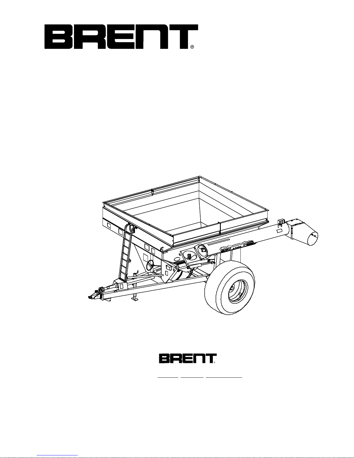
MODELS
674 & 672
Corner AugerTM GRAIN CART
Model 674 Beginning With Serial Number B1651100
Model 672 Beginning With Serial Number B1649100
®
250915H

1-2
SECTION II - PARTS PAGE
PTO ASSEMBLY ...................................... 2-2
PTO CLUTCH........................................... 2-3
UNDERCARRIAGE ................................... 2-4
AUGER..................................................... 2-6
BOX & ELECTRICAL................................ 2-8
DECALS ................................................. 2-10
SIDE BOARDS ....................................... 2-11
LOWER AUGER & DRIVELINE .............. 2-12
DRIVE LINE U-JOINT ASSEMBLY ......... 2-13
HUB ........................................................ 2-14
120 - 154" ADJUSTABLE AXLE ............. 2-16
45OGEAR BOX...................................... 2-18
14" AUGER CYLINDER.......................... 2-19
36" FLOW CONTROL DOOR CYLINDER.. 2-19
HYDRAULIC PTO DRIVE (OPTIONAL) .. 2-20
SCALE (OPTIONAL) ............................... 2-22
ELECTRICAL ............................................2-23
HYDRAULIC DRIVE KIT (OPTIONAL) .......2-24
SECTION III - SCALE
SCALE KIT LAYOUT & INSTALLATION ......3-2
SCALE MODEL 2000
OPERATION.......................................... 3-4
OPTIONAL FEATURES ......................... 3-5
INSTALLATION REQUIREMENTS......... 3-6
SHORT-FORM SET-UP/CALIBRATION ..... 3-7
SECTION IV - TARP
TARP PARTS ........................................... 4-2
TARP INSTALLATION .............................. 4-4
SECTION I - OPERATION PAGE
INTRODUCTION....................................... 1-3
SAFETY .................................................... 1-4
SET UP FOR FIELD OPERATION ........... 1-6
PLASTIC HOSE PIPE INSTALLATION..... 1-7
ELECTRICAL HOOK-UP .......................... 1-8
DUAL WHEELS ........................................ 1-9
TRACTOR HOOK-UP ..............................1-10
HYDRAULIC HOOK-UP ...........................1-10
OPERATION IN FIELD ............................1-10
AUGER FOLD ADJUSTMENT.................1-11
HYDRAULIC AUGER OPERATION .........1-12
ADJUSTABLE UNLOADING CHUTE .......1-13
SCALE WEIGHING PROCEDURE ..........1-13
LUBRICATION, MAINTENANCE .................1-14
SEASONAL STORAGE ...........................1-14
SERVICE TIPS ........................................1-15
AUGER....................................................1-15
120 - 154" ADJUSTABLE AXLE .............1-16
PTO .........................................................1-17
OPERATION.........................................1-17
SHIELDS ..............................................1-17
JOINTS .................................................1-17
SIZE......................................................1-18
LUBRICATION ......................................1-18
COUPLING PTO DRIVE SHAFT ..........1-18
CHAINS ................................................1-19
CLUTCHES...........................................1-19
GUARD.................................................1-20
CONE ...................................................1-20
QUICK DISCONNECT ..........................1-21
CLUTCH ...............................................1-22
DRIVELINE SAFETY PRECAUTIONS .....1-23
TABLE OF CONTENTS
•
• 09-22-03/122904-2

1-3
Your new Brent Corner AugerTM Grain Cart is designed to meet today’s
exacting operating requirements. You have chosen a product with numerous
operating features that will increase your harvesting efficiency for years to come.
A single auger, along with a rugged design throughout, will help keep
maintenance to a minimum. You have also purchased a unit that has other options
as your operation may change; such as a bolt-on axle that allows you to match new
tillage practices and row crop widths. There is an optional electronic scale package
that will provide yield per acre or accumulate bushels per field.
Your new Brent Grain Cart will add the efficiency, flexibility, and dependability
to profit in today’s agriculture.
The following pages will provide you information regarding operating and
maintenance instructions. Use this book to familiarize yourself with this new machine
and provide operating instructions to others.
INTRODUCTION
Wheel bolts tightened (re-check after initial use)
Tire pressures checked
Hardware tightened
Machine lubricated
Guards and shields in place
Safety and operating procedures reviewed
Field adjustment information reviewed
Lubrication procedures reviewed
Warranty information reviewed
Hydraulic hoses properly routed/fittings tight
PRE-OPERATIONCHECKLIST
THANK YOU FOR YOUR PURCHASE!
Please supply this information when you have questions or when ordering repair or re-
placement parts. Your dealer needs this information to give you prompt, efficient service.
Please fill out and retain this portion for your records. For warranty consideration, please
contact dealer where purchased.
The serial number plate is located on the front side of your Corner AugerTM Grain Cart.
Date of Purchase Model Serial #
Owner name Farm/Co. name
Address City
State Zip Code Phone # ( )
Dealer City State

1-4
.
ACCIDENTS
CAN BE PREVENTED
WITH YOUR HELP!
No accident-prevention program can be successful without the whole-hearted
cooperation of the person who is directly responsible for the operation of the equipment.
A large number of accidents can be prevented only by the operator anticipating
the result before the accident is caused and doing something about it. No power-driven
equipment, whether it be transportation or processing, whether it be on the highway, in
the harvest field, or in the industrial plant, can be safer than the person who is at the
controls. If accidents are to be prevented--and they can be prevented--it will be done
by the operators who accept the full measure of their responsibility.
It is true that the designer, the manufacturer, and the safety engineer can help;
and they will help, but their combined efforts can be wiped out by a single careless act
of the operator.
It is said that, "the best kind of a safety device is a careful operator." We, at
Unverferth Mfg. Co., Inc. ask that you be that kind of operator.
SAFETY PRECAUTIONS
Read this manual carefully before operating.
Never enter the grain cart while the auger is running.
Make sure PTO guard is kept in place.
Never allow anyone on the unit while moving through the field.
Be careful when moving unit near electrical lines with discharge auger up.
Never tow a loaded unit more than 8 m.p.h. or on a road.
Never exceed the maximum recommended hitch pin size which allows for
uneven terrain.
Make use of night-time lighting provided on your new cart.
Use caution when unloading on the go, while moving through gullies, wash-
outs, and uneven terrain.
Always check behind you before backing up.
Counter-weight your tractor front end.
Be careful on steep slopes. A loaded grain cart is hard to stop.
Do not fold or unfold auger while moving.
When auger is not in use, be sure to fold to the rest position.
Never unhook a grain cart while it is being loaded.
Turn the tractor power off and remove the key from the ignition before servicing
the attached implement.
Tow only an empty cart on-road and have a rated safety chain attached.
•
•12-19-01
.
.
.
.
.
.
.
.
.
.
.
.
.
.
.
.
1-5
•04-01-02
NOTE! This SAFETY ALERT SYMBOL is found throughout this manual. It is used
to call attention to instructions involving your personal safety and the safety of others.
Failure to follow these instructions can result in INJURY OR DEATH.
SIGNAL WORDS:
DANGER: Indicates an imminently hazardous situation that, if
not avoided, will result in death or serious injury.
WARNING: Indicates a potentially hazardous situation that, if
not avoided, could result in death or serious injury.
CAUTION: Indicates a potentially hazardous situation that, if
not avoided, may result in minor or moderate
injury.
This symbol means
ATTENTION!
BECOMEALERT!
YOURSAFETYISINVOLVED!
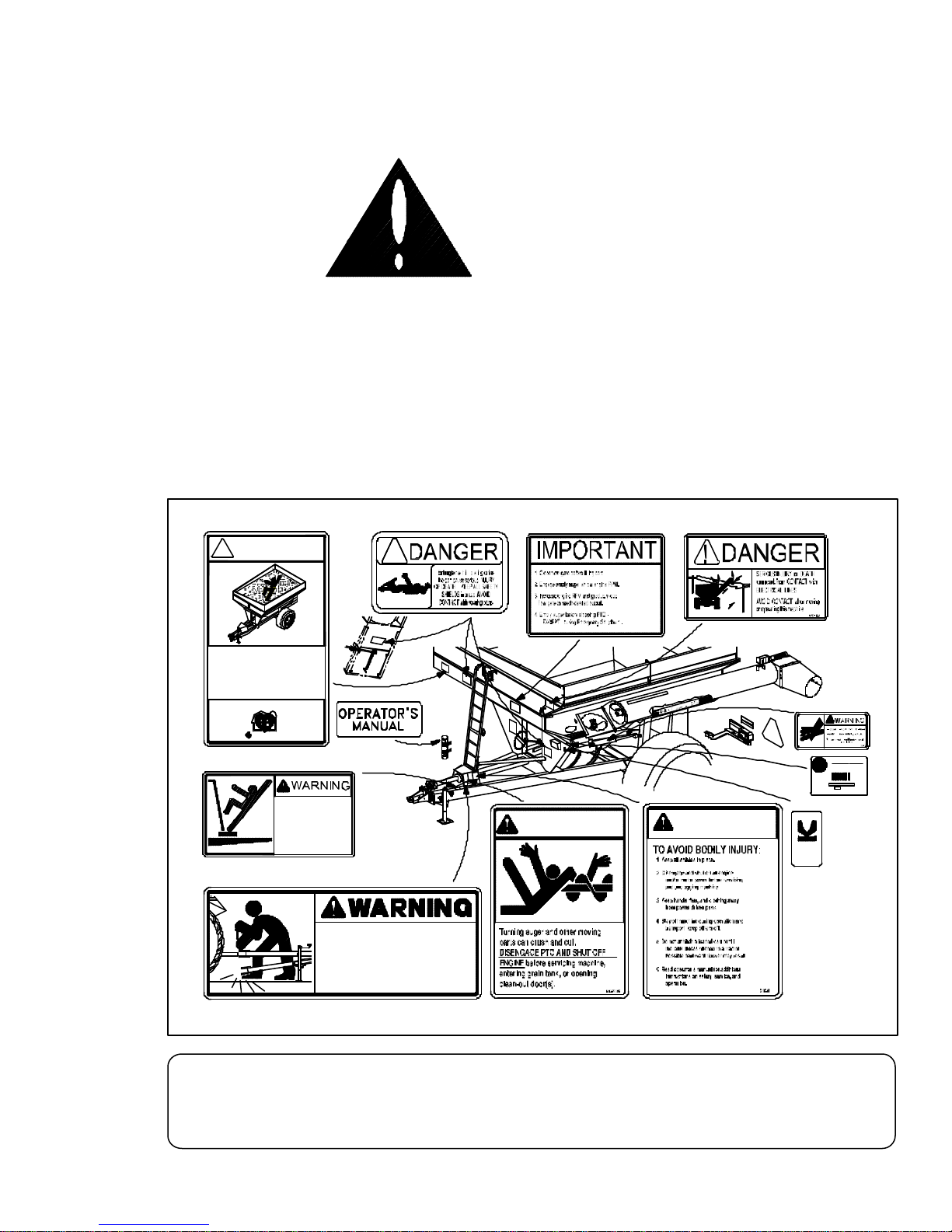
IMPORTANT
Replacelost,damaged,painted,orunreadabledecalsimmediately. Ifpartsthathavedecalsare
replaced,also make sureto install newdecals. These decals inform andremind theoperator
with operational information and safety messages.
251924
TAKEWEIGHTOFFOFTHETONGUE.
AND RAISE OR LOWER HITCH TO
LOWER JACK STAND INTO POSITION
BEFORE REMOVING HITCH PIN,
96764
TONGUE CAN DROP RAPIDLY
CAUTION
NO RIDERS
FALLING OFF can
cause SERIOUS
INJURY or DEATH
9003476
9003477
WARNING
Just Kids 9003478
NEVER PLAY
FLOWING GRAIN TRAPS
VICTIM in SECONDS !
Farm Safety
and SUFFOCATES
IN or ON the GRAIN
! DANGER !
95046A
9003478
9003476
9003475
95046 9003474
9003477
95445
TM
419-532-3121
MFG. CO., INC. - U.S.A.
Unverferth
SERIAL NO.
PRODUCT:
FEMA
ASSOCIATION
MANUFACTURERS
FARMEQUIPMENT
MEMBER
91605
9000917
9000917
91302
96764
Table of contents
Other brent Farm Equipment manuals

Popular Farm Equipment manuals by other brands

Schaffert
Schaffert Rebounder Mounting instructions

Stocks AG
Stocks AG Fan Jet Pro Plus 65 Original Operating Manual and parts list

Cumberland
Cumberland Integra Feed-Link Installation and operation manual

BROWN
BROWN BDHP-1250 Owner's/operator's manual

Molon
Molon BCS operating instructions

Vaderstad
Vaderstad Rapid Series instructions


