Bresee U82 User manual


catalogue
1 packing list ························································································ 3
2 product introduction············································································· 3
2.1 product description ···································································· 3
2.2 product dimensions ··································································· 4
2.3 structure description ·································································· 5
3 installation instructions········································································· 7
3.1 wall mounted installation····························································· 7
4 wiring instructions ··············································································· 9
4.1 schematic diagram of tail line······················································· 9
4.2 interface description··································································10
5 Equipment Use ·················································································12
5.1 starting equipment····································································12
5.2 entry······················································································12
5.2.1 browser configuration ······················································12
5.2.2 login web interface··························································13
5.2.3 new personnel ·······························································14
5.3 recognition··············································································14

1
statement
Without the written permission of the company, no unit or individual shall
extract or copy part or all of the contents of this manual without authorization,
and shall not disseminate it in any form. Due to product version upgrade or
other reasons, the contents of this manual will be updated from time to time.
This manual is only used as a guide, and all statements, information and
suggestions in this manual do not constitute any express or implied warranty.
The company shall not be liable for any special, incidental, accidental or
indirect damage caused by the use of this manual or the use of the
company's products, including but not limited to the loss of business profits,
loss of data or documents, abnormal operation of products and information
disclosure caused by network attack, hacker attack, virus infection, etc.
Safety instructions
This is a class a product, which may cause radio interference in the living
environment. In this case, users may be required to take practical
measures against their interference.
Please disconnect the power supply before moving the equipment. Be
careful to prevent electric shock when moving. Once the power cord is
inserted into the power supply, the equipment will be powered on.
Please ensure that the equipment is installed stably and reliably, the
surrounding ventilation is good, and the ventilation outlet must be
unblocked when the equipment is working.
Please ensure that the equipment works within the allowable
temperature, humidity and power supply requirements, and is well
grounded to meet the lightning protection requirements, and avoid being
placed in dusty, strong electromagnetic radiation, vibration and other
places.
Please protect the power cord from trampling or squeezing, especially at
the plug, power socket and the contact from the device.

2
After installation, please check the correctness to avoid human injury and
equipment component damage due to wrong connection during power
on.
Abnormal power failure may cause equipment damage or abnormal
function. If the equipment is used in the environment of frequent power
failure, please provide ups.
Make the equipment work within the allowable temperature and humidity
range, and avoid being placed in places such as extrusion, vibration,
extreme heat, extreme cold and strong electromagnetic radiation. To
avoid fire and electric shock hazards, do not allow water or other liquids
to flow into the equipment during use.
If the equipment cannot be maintained due to unauthorized operation,
the company will not bear all the consequences arising therefrom.

3
1 packing list
If you find any items damaged or missing, please contact your local dealer in
time.
No
item
number
unit
1
DR21-8UW
1
pcs
2
Tail line - grid port
1
pcs
3
Tail line - full function
1
pcs
4
The power adapter
1
pcs
5
Accompanying instructions
1
pcs
6
certificate
1
pcs
7
warranty card
1
pcs
8
Wall mount bracket set
1
pcs
9
Wall mount bracket sticker
1
pcs
10
Screw package
1
pcs
2 product introduction
2.1 product description
U82/T82 is a high-performance and reliable product. This product supports a
variety of recognition modes such as white list recognition, IC card
verification. It adopts the idea of industrial appearance design, with light and
thin body, smooth lines, high recognition rate, large storage capacity, fast
recognition and so on. Through the access management platform, multiple
applications such as access control management, attendance management
and visitor management can be realized, which is suitable for various
scenarios such as parks, universities, enterprises, communities and
hospitals.

4
U82 T82
model: DR21-8UW model: DE21-8TW
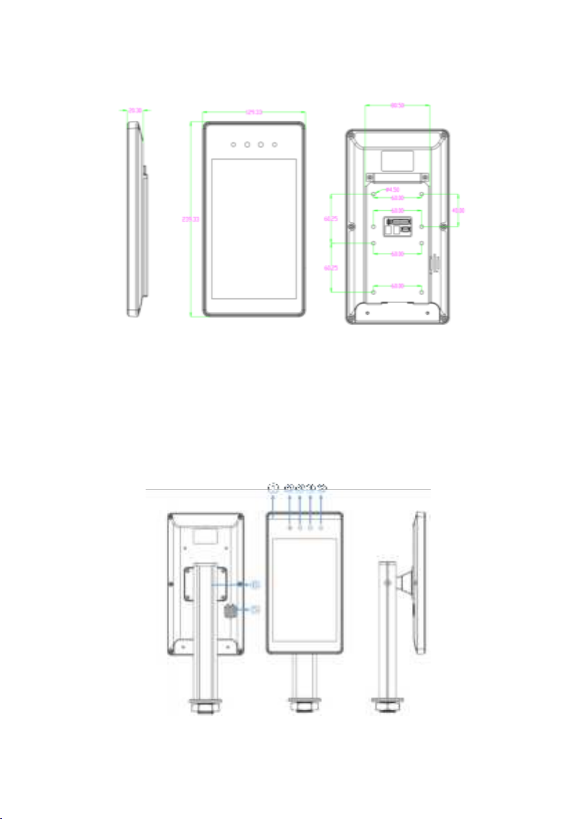
2.2 product dimensions
U82 Equipment dimension drawing, as shown in Figure 2-1.
chart 2-1
5
T82 Equipment dimension drawing, as shown in Figure 2-2.
chart 2-2
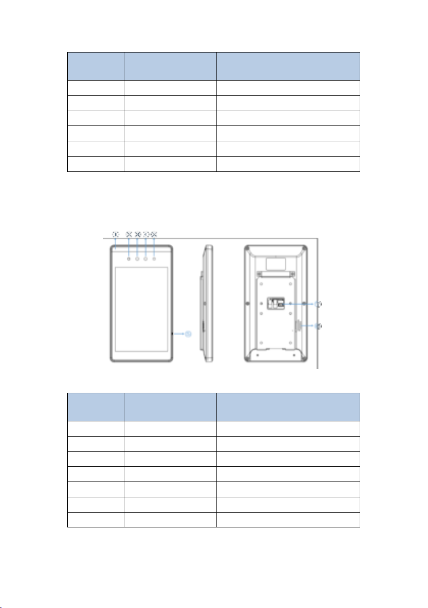
2.3 structure description
The appearance of U82 equipment structure is shown in Figure 2-3. Please
refer to the real object for details.
chart 2-3
6
Serial
number
name
explain
1
Led fill light
Fill RGB camera
2
Infrared fill light
Fill in light for infrared camera
3
Infrared camera
Take infrared images
4
RGB camera
Take visible images
5
speaker
Play voice prompt
6
Tail line output hole
Panel tail line hole
The appearance of T82 equipment structure is shown in Figure 2-4. Please
refer to the real object for details.
chart 2-4
Serial
number
name
explain
1
Led fill light
Fill RGB camera
2
Infrared fill light
Fill in light for infrared camera
3
Infrared camera
Take infrared images
4
RGB camera
Take visible images
5
Mic outlet
For voice intercom
6
speaker
Play voice prompt
7
Tail line output hole
Panel tail line hole

7
3 installation instructions
Please check before installing the product to ensure that the product can
work normally.
This document provides wall mounted installation methods for reference,
and other installation instructions can be obtained by contacting our
personnel;
3.1 gate type installation
chart 3-1
Step 1: as shown in Figure 3-1, if there is no hole on the gate panel, it is
necessary to use a punch to make a circle with a diameter of 35mm on the
gate panel;
Step 2: as shown in Figure 3-2, thread the external wiring of the identification
terminal and the vertical pole support through the hole on the gate panel;
Step 3: as shown in Figure 3-3, thread and tighten the upright nut from below
to fix the identification terminal;
Chart3-2
chart 3-3

8
Step 4: as shown in Fig. 3-4, loosen the screw on the upright support, adjust it
to an appropriate angle and tighten it again;
chart 3-4
3.2 wall mounted installation
chart 3-5
Step 1: as shown in Figure 3-5, fix the sheet metal on the back of the machine
body with screws ①;
Step 2: Mark four positioning points on the wall to confirm the installation
position of the wall hanging support;
Step 3: as shown in Figure 3-5, align the four holes on the wall hanging
bracket with the wall positioning point, lock four self tapping screws ②, and fix
the wall hanging bracket;
9
Step 4: as shown in Figure 3-5, fasten the access control terminal sheet
metal to the wall hanging support through position ③;
Step 5: as shown in Figure 3-5, use screws ④ to fix the access control
terminal and the wall hanging bracket;
Step 6: after installation, as shown in Figure 3-6;
chart 3-6
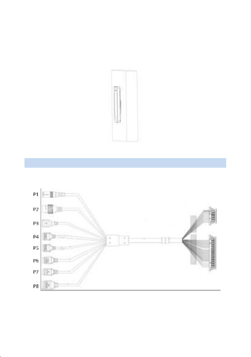
4 wiring instructions
4.1 U82 schematic diagram of tail line
chart 4-1

10
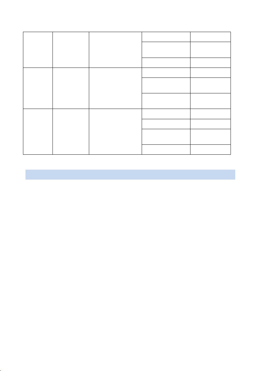
U82 interface description
Serial
number
Interface
name
Interface
description
Pin color
Pin
description
P1
RJ45
network
port
Wired network
port
communication
/
RJ45
network port
P2
12V power
supply
12V power input
/
DC_12V
P3
USB2.0
USB2.0 Interface
/
USB
interface
P4
Relay
output 1
Output IO signal
WHITE
NO1
ORANGE
COM1
RED
NC1
P5
Relay
output 2
Output IO signal
GRAY
NO2
WHITE/ORANG
E
COM2
WHITE/RED
NC2
P6
RS485
RS485
communication
BLACK
GND
RED
5V
WHITE/PURPL
E
RS485+
BROWN
RS485-
P7
WG_OUT
Wigan signal
output
BLACK
GND
YELLOW/GRAY
WG_OUT_D
0
WHITE/YELLO
W
WG_OUT_D
1
P8
ALM_IN、
SEN_IN
Alarm signal input,
door magnetic
signal input
BLACK
GND
PINK
ALM_IN1
YELLOW/BLAC
K
ALM_IN2
WHITE/GREEN
SEN_IN1

11
4.2 T82 schematic diagram of tail line
chart 4-2
T82 interface description
Serial
number
Interface
name
Interface
description
Pin color
Pin
description
P1
RJ45
network
port
Wired network
port
communication
/
RJ45
network port
P2
12V power
supply
12V power input
/
DC_12V
P3
USB2.0
USB2.0 Interface
/
USB
interface
P4
Relay
output 1
Output IO signal
WHITE
NO1
ORANGE
COM1
RED
NC1
P5
Relay
output 2
Output IO signal
GRAY
NO2
WHITE/ORANG
E
COM2
WHITE/RED
NC2
P6
RS485
RS485
BLACK
GND
12
5 Equipment Use
5.1 starting equipment
After correct installation, connect the power adapter to the mains and the
other end to the equipment power interface to start the equipment. When the
display is powered on, it indicates that the device is started successfully.
5.2 entry
5.2.1 browser configuration
The following takes windows 10 system and Google browser as examples.
1. Please check the network connection between the client computer and the
terminal before logging in to the web interface.
2. It is recommended to use 360 speed browser, chrome, Firefox and other
non IE core browsers.
3. For better display, please use the recommended resolution: 1600 × 900。
communication
RED
5V
WHITE/PURPL
E
RS485+
BROWN
RS485-
P7
WG_OUT
Wigan signal
output
BLACK
GND
YELLOW/GRAY
WG_OUT_D
0
WHITE/YELLO
W
WG_OUT_D
1
P8
ALM_IN、
SEN_IN
Alarm signal input,
door magnetic
signal input
BLACK
GND
PINK
ALM_IN1
YELLOW/BLAC
K
ALM_IN2
WHITE/GREEN
SEN_IN1
13
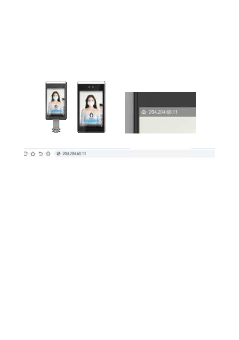
5.2.2 login web interface
1. DHCP login (factory default DHCP);
Enter the IP address in the upper left corner of the device display in the
browser to enter the web login interface, as shown in Figure 5-1 and figure
5-1
chart 5-1 IP display of main interface
chart 5-2 IP access of input device
2.Static IP login:
Step 1: click the < setting > button on the device display screen interface;
Enter the initial password < admin > to enter the network configuration
interface.
Step 2: close DHCP and modify the static IP address, subnet mask and
default gateway
Save after, power off and restart the equipment.
Step 3: enter the modified IP in the browser to enter the web login interface.
●Default static IP:192.168.0.13;
●Subnet mask:255.255.255.0;
3.Log in to the web interface:
After accessing the IP address of the device through the browser, enter the
user name and password of the device, and click OK
Click < login >, and you can enter the web management interface.

14
Default user name: admin; Default password: admin.
5.2.3 new personnel
1. Select [personnel management - personnel information] interface and
select the personnel library to add personnel;
2. In the personnel list operation bar, click < add >;
3. In the pop-up new personnel interface, refer to the following table to
configure personnel information;
4. Click < save > to finish adding personnel.
5.3 recognition
The tester can realize the recognition function by placing it directly in front of
the recognition equipment.
Note: detailed instructions for the use of recognition terminal can be obtained
by contacting our personnel.
6 EU DECLARATION OF CONFORMITY
Hereby, Bresee Technology Co.,Ltd. declares that the radio equipment type
DR21-8UW , DE21-8TW is in compliance with Directive 2014/53/EU.
The full text of the EU declaration of conformity Please see attachment DOC
Letter
7 FCC Caution.
§ 15.19 Labeling requirements.
This device complies with part 15 of the FCC Rules. Operation is subject to
the following two conditions: (1) This device may not cause harmful
interference, and (2) this device must accept any interference received,
including interference that may cause undesired operation.

15
§ 15.21 Information to user.
Any Changes or modifications not expressly approved by the party
responsible for compliance could void the user's authority to operate the
equipment.
§ 15.105 Information to the user.
Note: This equipment has been tested and found to comply with the limits for
a Class B digital device, pursuant to part 15 of the FCC Rules. These limits
are designed to provide reasonable protection against harmful interference in
a residential installation. This equipment generates uses and can radiate
radio frequency energy and, if not installed and used in accordance with the
instructions, may cause harmful interference to radio communications.
However, there is no guarantee that interference will not occur in a particular
installation. If this equipment does cause harmful interference to radio or
television reception, which can be determined by turning the equipment off
and on, the user is encouraged to try to correct the interference by one or
more of the following measures:
-Reorient or relocate the receiving antenna.
-Increase the separation between the equipment and receiver.
-Connect the equipment into an outlet on a circuit different from that to which
the receiver is connected.
-Consult the dealer or an experienced radio/TV technician for help.
This equipment complies with RF radiation exposure limits set forth for an
uncontrolled environment. This equipment should be installed and operated
withminimum distance 20cm between the radiator &your body.
This manual suits for next models
3
Table of contents


