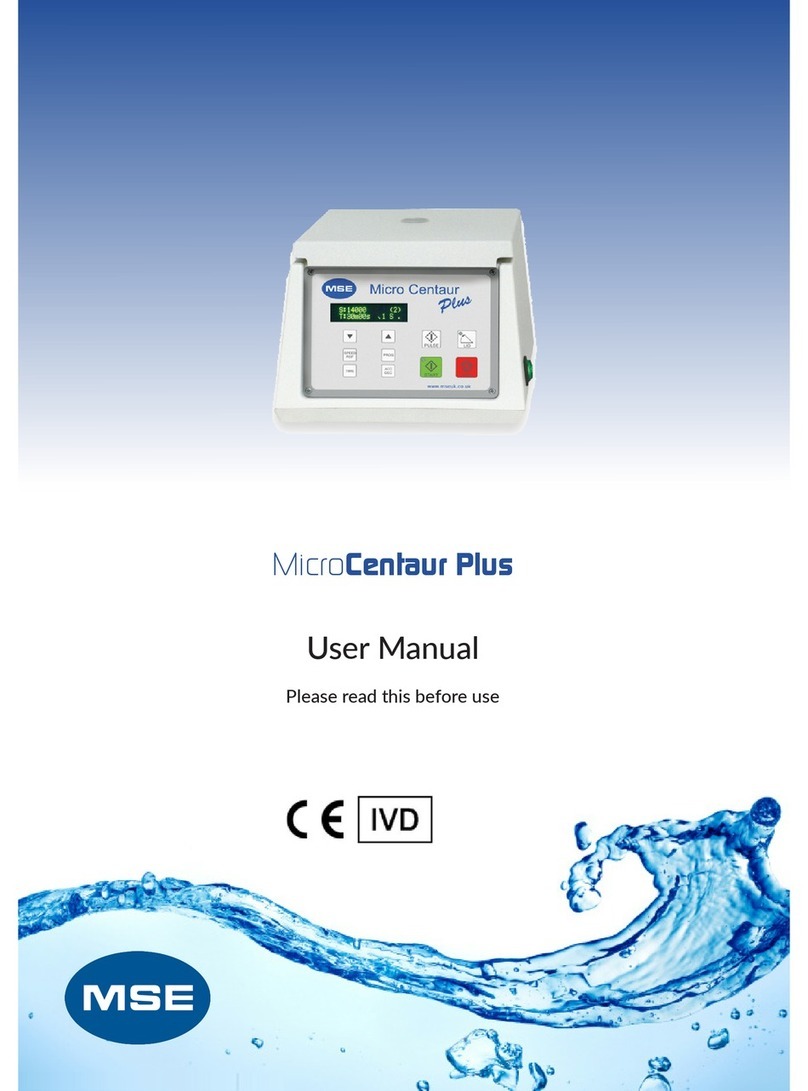
Brewer Science Cee 200X User manual

1
Brewer Science®
Cee®200X
Precision Spin Coater
Operator/User Manual
New users: Read this manual in its entirety before operating the equipment.
Version 10-2012-A
© 2012 Brewer Science, Inc.

2
Contents
1. Products Covered in This Manual ................................................. 4
2. Confidentiality Statement, Warranty, and Instructions
for Returning Materials ............................................................................... 4
2.1 Confidentiality Statement..................................................................................... 4
2.2 Warranty .............................................................................................................. 4
2.3 Instructions for Returning Materials ..................................................................... 5
3. Introduction to the Cee®200X Precision Spin Coater ....... 6
3.1 Programmability................................................................................................... 6
3.2 Precision.............................................................................................................. 6
3.3 Reliability ............................................................................................................. 7
3.4 Bowl Design......................................................................................................... 7
3.5 Utilities ................................................................................................................. 7
3.6 Dimensions.......................................................................................................... 7
4. Spin Coater Overview............................................................................ 8
4.1 Model and Revisions ........................................................................................... 8
4.2 System Specifications.......................................................................................... 8
4.3 Safety Hazards/Precautions ................................................................................ 8
4.3.1 Overview of Equipment-Specific Hazards................................................. 8
4.3.2 Electrical................................................................................................... 8
4.3.3 Mechanical ............................................................................................... 9
4.3.4 Chemical................................................................................................... 9
4.3.5 Lockout/Tagout Procedures and Information............................................ 10
4.3.6 Intended Use of Machine.......................................................................... 10
4.4 Installation ........................................................................................................... 10
4.4.1 Facilities Requirements ............................................................................ 10
4.4.2 Environment ............................................................................................. 11
4.4.3 Unpacking and Inspection ........................................................................ 11
4.4.4 System Installation and Setup .................................................................. 11
5. Software......................................................................................................... 12
5.1 Startup and Run Screen ...................................................................................... 12
5.1.1 Startup with Passwords Enabled .............................................................. 12
5.1.2 Run Screen............................................................................................... 13
5.2 Spin Process Screen ........................................................................................... 14
5.2.1 Running a Spin Process ........................................................................... 16
5.2.2 Centering a Substrate............................................................................... 17
5.2.3 Starting a Process .................................................................................... 18
5.2.4 Aborting a Process ................................................................................... 18
5.2.5 Process Complete .................................................................................... 19
5.2.6 Running Multiple Iterations ....................................................................... 19

3
5.3 Edit Screen .......................................................................................................... 20
5.3.1 Spin Recipe Edit Screen........................................................................... 20
5.3.2 Writing a Spin Recipe ............................................................................... 22
5.3.3 Entering Data............................................................................................ 22
5.3.4 Recipe Management................................................................................. 24
5.3.5 Recipe Backup ......................................................................................... 25
5.3.6 Desktop Recipe Editing ............................................................................ 25
5.4 Diagnostics Screen.............................................................................................. 26
5.4.1 Spin Diagnostics Screen........................................................................... 27
5.5 User Configuration Screen .................................................................................. 29
5.5.1 User Spinner Configuration Screen .......................................................... 30
5.5.2 Naming Dispenses on the User Spinner Configuration Screen ................ 31
5.5.3 Selecting Empty Sensors on the User Spinner Configuration Screen ...... 31
5.5.4 Password Configuration Screen ............................................................... 32
5.5.5 User Level Access.................................................................................... 33
5.6 Navigation Bar ..................................................................................................... 34
5.7 LIVE Update Feature........................................................................................... 35
5.7.1 Limitations of LIVE Update ....................................................................... 36
6. Service and Maintenance.................................................................... 37
6.1 Maintaining the Vacuum Liquid Trap ................................................................... 37
6.2 Spin Chuck Replacement .................................................................................... 37
6.3 Troubleshooting Chart ......................................................................................... 38

4
1. Products Covered in This Manual
This manual covers the Brewer Science®Cee®200X series of spin coaters. This
manual is to be used to install, operate, and troubleshoot this spin-coating equipment
series. New users should read this manual in its entirety before operating the
equipment.
2. Confidentiality Statement, Warranty, and Instructions for
Returning Materials
2.1 Confidentiality Statement
Information supplied is only for use during operation and/or maintenance of Cee®
equipment. Neither this document nor the information it contains shall be
disclosed to others for manufacturing or any other purpose without written
authorization from Brewer Science, Inc.
2.2 Warranty
Brewer Science, Inc., warrants to the original purchaser (Buyer) that the equipment is
free from defects in material and workmanship under normal use and service in
accordance with Brewer Science instructions and specifications.
Buyer shall promptly notify Brewer Science of any claim against this warranty, and any
item to be returned to Brewer Science shall be sent with transportation charges prepaid
by Buyer, clearly marked with a Return Material Authorization (RMA) number obtained
from Brewer Science Equipment Customer Support. (See section 2.3.)
Brewer Science’s obligation under this warranty is limited to the repair or replacement,
at Brewer Science’s option, of any equipment, component, or part that is determined by
Brewer Science to be defective in material or workmanship. This obligation shall expire
one (1) year after the initial shipment of the equipment from Brewer Science.
This warranty shall be void if:
a) Any failure is due to the misuse, neglect, or improper installation of or accident to
the equipment.
b) Any major repairs or alterations are made to equipment by anyone other than a
duly authorized representative of Brewer Science. Representatives of Buyer may
be authorized to make repairs to the equipment without voiding warranty upon
completion of the appropriate Brewer Science®Cee®equipment training
program.
c) Replacement parts are used other than those made or recommended by Brewer
Science.

5
BREWER SCIENCE MAKES NO OTHER WARRANTIES, EXPRESSED OR IMPLIED,
WITH RESPECT TO EQUIPMENT. NO WARRANTY IS MADE AS TO THE
MERCHANTABILITY OF THE EQUIPMENT NOR ITS FITNESS FOR ANY
PARTICULAR PURPOSE. In no event shall Brewer Science be liable for consequential
loss or damages, however caused. No person or representative of Brewer Science is
authorized to assume for Brewer Science any liability in connection with Equipment nor
to make any change to this warranty unless such change or modification is put in writing
and signed by an authorized representative of Brewer Science.
This warranty shall be governed by the laws of the state of Missouri, U.S.A.
2.3 Instructions for Returning Materials
Any materials, parts, or equipment returned to Brewer Science Equipment Customer
Support must be clearly labeled with a Return Material Authorization (RMA) number.
To obtain an RMA number, contact:
Brewer Science Equipment Customer Support
Telephone: (573) 364-0300
Facsimile: (573) 364-9513
Web Address: http://www.brewerscience.com
Shipping information for use in returns with an RMA number:
Brewer Science, Inc.
Attn: Equipment Customer Support
2401 Brewer Drive
Rolla, Missouri 65401
USA

6
3. Introduction to the Cee®200X Precision Spin Coater
The Cee®200X precision spin coater delivers track-quality performance, with
revolutionary interface capabilities and the utmost in chemical compatibility, in an
efficient, space-saving design.
Fully programmable and user-friendly, the Brewer Science®Cee®200X precision spin
coater features the accuracy and repeatability needed to eliminate processing variability
from critical experiments. With its convenient, compact footprint, wide range of chemical
compatibility, and durability, this easy-to-use benchtop system will provide years of
high-performance operation, making the purchase of a Cee®200X tool a smart and
cost-effective decision.
3.1 Programmability
•PC-controlled
•PC-based touch screen interface and display
•Full-color alphanumeric-capable graphical user interface (GUI)
•250,000 process recipe programs onboard
•A virtually unlimited number of user-defined recipe program steps
•0.1-second resolution for step times (max. step time: 9,999.9 seconds)
•Spin speed: 0 to 6,000 rpm (0 to 12,000 rpm option at no charge; 0 to 16,000 rpm
option available)
•Spin speed acceleration:
o0 to 30,000 rpm/s unloaded
o0 to 23,000 rpm/s with a 200-mm substrate
o0 to 3,000 rpm/s with a 6 in ×6 in ×0.250 in photomask recessed chuck
•Connectivity: USB/Ethernet port for communications for uploading/downloading
process parameters with offline firmware standard (offline recipe number and steps
unlimited)
•System capable of controlling third-party host software of high-end IDI-Cybor or
Mykrolis positive displacement pumps
•Simultaneous dual automated dispense capability
•Bi-directional speed control/oscillating chuck
•Iteration software (recipe looping)
•Dispense or component outputs: 50
•Security: Password protection option available at no charge
•In-process/dynamic speed/acceleration control
3.2 Precision
•Spin speed repeatability: < 0.2 rpm
•Spin speed resolution: < 0.2 rpm
•Substrate sizes: < 1 cm to 200 mm round; 7 in ×7 in square

7
3.3 Reliability
•Indirect drive system protects the spin motor from contact with process chemicals
and solvents
•Vacuum and lid interlock standard
•Industry-leading reliability and uptime
•1-year full warranty on parts and labor
•Free remote technical support (phone, email, fax) for the life of the product
•Application process assistance for the life of the product
3.4 Bowl Design
•Teflon®spin bowl for material compatibility
•Integrated bowl ring to eliminate material migration
•Optional stainless steel bowl (for all-stainless-steel construction)
•Optional polyethylene bowl (educational package) available
•Optional polyethylene liners available
•Optional polyethylene/Teflon®splash ring
•Closed and optional open lid designs for process flexibility
•Drain and exhaust ports located in the bottom of bowl
•Optional nitrogen purge for an inert spin environment
3.5 Utilities
•Voltage ranges: 100, 110-125, 208-240 VAC, 50/60 Hz
•Power requirements: 655 watts
•Drain port: ¾in OD
•Exhaust port: 1 in OD
•Vacuum: 25 in Hg
•Exhaust: 50 cfm at 0.2 in water
•Nitrogen or CDA (for automated dispenses): 70 psi
3.6 Dimensions
•13.25 in (33.65 cm) W ×19 in (48.26 cm) D ×12 in (30.48 cm) H
•Machine weight: 40 lb (18.14 kg)
•Shipping weight: 100 lb (45.36 kg)

8
4. Spin Coater Overview
4.1 Model and Revisions
The model and serial number information for the Cee®200X spin coater is located on
the rear panel near the power inlet. Software version information can be found on the
main software screen. See section 5, Software, for screen shots and a detailed
explanation of the system software.
4.2 System Specifications
Maximum spin speed
6,000 or 12,000 or 16,000 rpm
(depending on option purchased)
Maximum ramp
30,000 rpm/s
Speed accuracy
< 0.2 rpm
Maximum substrate size
accommodated by bowl
200 mm
Recipe storage
Virtually unlimited
Power
100-120 or 220 volts AC, single phase
Weight
40 lb
4.3 Safety Hazards/Precautions
Read this manual in its entirety before operating the machine.
4.3.1 Overview of Equipment-Specific Hazards
The unit is very heavy and proper precautions should be taken when handling the
machine to minimize risk of injury. Labels are placed on the machine to identify areas
where caution is needed during operation.
4.3.2 Electrical
General Hazard
Pinch Point Warning
Notes:
High voltage is present in the machine. Disconnect the power before
servicing.
Stored electrical energy is present in the machine. Before servicing,
allow sufficient time for discharge. The servo amp has a charge light; do
not service the machine until this light has gone out.

9
4.3.3 Mechanical
General Hazard
Pinch Point Warning
Notes:
This machine uses compressed gases that can provide motive force to
components and can expand violently upon decompression. Disconnect
N2or clean dry air (CDA) before removing any panels.
This machine has components capable of very-high-speed rotation.
Ensure all lids and panels are in place before activating the rotational
features.
Ensure that all panels are on and in their correct locations before
powering up or operating the machine.
When opening the lid, be aware of the pinch point at the hinge cover.
Open the lid only by using the handle on the lid.
The unit is very heavy, and proper precautions should be taken when
handling or moving the machine to minimize risk of injury.
Always wear the proper personal protective equipment (PPE) for the job,
including safety glasses, gloves, and other equipment as needed to
protect from mechanical and chemical hazards.
4.3.4 Chemical
Notes:
Ensure all chemicals and materials being used in the tool are chemically
compatible with the systems they will come in contact with during use.
Consider all wetted parts of the storage, supply, dispense, and waste
systems.
Ensure the chemical compatibility of all chemicals with each other. All
dispensed materials are held in one common waste storage tank. Before
use, check for the potential for reactions between chemicals.
Flammable chemicals. No open flames/sparks.
Relieve pressure before opening canisters, tanks, cartridges, or syringes
to refill.
Relieve pressure and shut off chemical valves before removing spin lid
or changing backside rinse (BSR) tubes, edge bead removal (EBR)
tubes, or any other dispense nozzle or spray tip.

10
Flush tubing and valves with an appropriate solvent and drain system
before servicing.
When draining the waste tank, use appropriate containers and
connection methods.
Ensure proper ventilation/exhaust is used at all times.
Always wear the proper personal protective equipment (PPE) for the job,
including safety glasses, gloves, and other equipment as needed to
protect from mechanical and chemical hazards.
4.3.5 Lockout/Tagout Procedures and Information
Before servicing, turn off the machine and remove the power inlet cord by disconnecting
the plug where it enters the machine.
4.3.6 Intended Use of Machine
The Cee®200X spin coater is intended for use in semiconductor or optical materials
applications. It is primarily intended for substrates up to the maximum stated size.
The Cee®200X spin coater is not intended for use in food or medical applications or in
hazardous locations.
The Cee®200X spin coater is intended for use only by properly trained personnel
wearing the proper PPE. Anyone who is not trained in the proper use of this
equipment and who has not fully read this manual should not operate this
equipment.
The Cee®200X spin coater is intended for use in a clean room environment to provide
the proper processing conditions for the substrates. If it is used outside of a clean room
environment, substrate cleanliness may be compromised.
The Cee®200X spin coater is not intended for use in a hazardous or explosive
environment.
4.4 Installation
4.4.1 Facilities Requirements
The Cee®200X spin coater requires the following utilities for operation:
•Voltage: Single-phase 100-120 VAC at 10 amps
•Vacuum supply: 20 in Hg
•Nitrogen supply: 45-55 psi (auto dispense)
•Exhaust port: 1 in OD
•Drain port: ¾in OD

11
4.4.2 Environment
The Cee®200X spin coater should be operated in a clean, low-humidity environment.
4.4.3 Unpacking and Inspection
Thoroughly check the equipment for shipping damage. If physical damage is seen,
DO NOT APPLY POWER! Contact Brewer Science Equipment Customer Support
immediately.
The following items should be included with the shipment:
One (1) Cee®200X spin coater unit
One (1) power cord with female power connector
One (1) anodized aluminum stylus
One (1) operator/user manual
The following optional items may be included:
Spin chuck with screws
Dispense controllers
Dispense valves
Dispense nozzles
Dispense hubs
4.4.4 System Installation and Setup
1. Lift the unit out of the packing crate by grasping the bottom only. Do not lift the
unit by any of the top covers or protrusions. Do not roll or turn the unit on its side
or ends.
2. Remove plastic wrap and packing foam.
3. Place the Cee®200X spin coater on a table of proper height and strength so that
the controls and spin chuck are at the proper ergonomic height.
4. Level the machine using the feet so that the spin chuck is level from front to back
and side to side.
5. Thoroughly clean the spin bowl and spin chuck.
6. Connect vacuum, N2, drain, and exhaust lines.
7. Plug in the machine.
8. Once the unit is plugged in, only the cooling fan should be powered, not the
display.
9. Switch the ON/OFF power switch to ON.
10.The display should momentarily show a boot screen and then show the main
screen. Please be patient to allow the booting process to complete.

12
5. Software
5.1 Startup and Run Screen
5.1.1 Startup with Passwords Enabled
If the Cee®200X unit has passwords enabled, the initial screen will be blank with login
and logout buttons.
To log in, press the Login button, shown in the figure above, to view the touch screen
keyboard, and then enter your password. By default, the passwords for a Cee®200X
tool are:
Super User Level: CEE
User Level: 200X
Maintenance: DIAG

13
5.1.2 Run Screen
If login is successful, or if passwords are not enabled, the following Run screen should
appear:
From this screen the user can go directly to the Spin Process screen by pressing the
large button in the left-center of the screen. Navigating to other windows is also possible
by using the navigation bar at the bottom of the screen.

14
5.2 Spin Process Screen
The Spin Process screen is used to run and monitor spin-coating processes using the
Cee®200X tool’s software.
The controls and indicators found on the Spin Process screen are listed below:
1. Recipe Name: The name of the currently loaded recipe.
2. LIVE Update button: Allows the user to update the process that is currently
running. This button is activated only during a running process. More information on
LIVE Update is available in the LIVE Update section, section 5.7. LIVE Update is not
available on all models.
3. Load button: Navigates to the recipe selection screen (section 5.2.1) to select the
process settings.
4. Edit Recipe button: Navigates to the Spin Process editor if a recipe is loaded. If a
recipe is not loaded, it will navigate to the recipe selection screen (section 5.2.1).
5. Lid Closed indicator: Shows the current state of the Lid Closed sensor.
6. Substrate Present indicator: Shows the state of the Spin Chuck Vacuum sensor.
7. Step indicator: Shows the current step of the process.
8. Time indicator: Shows the time remaining on the current process step.
9. Speed indicator: Shows the current speed of the spindle.

15
10.Exhaust indicator: Shows the current setting of the programmable exhaust.
(Programmable exhaust is not available on all models.)
11.Dispense indicators: Show which dispenses are currently activated.
12.Iteration setting: Allows the currently selected process to run consecutively for the
entered number of times without stopping. (Iterative processing is not available on all
models.)
13.Process button: The process button has four modes:
a. Start Centering: Starts the wafer spinning very slowly to check for centering
on the spin chuck.
b. Start Process: Starts the selected process.
c. Abort: Aborts a currently running process.
d. OK: Turns off the Process Complete alarm.
14.Vacuum Hold/Release button: Allows the user to actuate the vacuum of the spin
chuck as he/she centers the substrate.
15.Center button: This button will only appear if a non-zero time is set for the centering
time on the Spin Configuration page. This button will re-run the centering process.
This process can be run as many times as necessary until the Start Process (13)
button (13) is pressed.

16
5.2.1 Running a Spin Process
To run a spin process with a substrate, a recipe must first be loaded. Pressing the Load
button will bring up the recipe selection screen (see below). To select a recipe, double-
press on the desired recipe or select the desired recipe and press Enter.

17
5.2.2 Centering a Substrate
The Cee®200X tool has two methods of centering a substrate. The Centering Time
parameter set on the User Spinner Configuration screen determines the method used.
If the Centering Time (4) parameter is set to 0 seconds, pressing the Start Centering
button will start the Spin Chuck spinning. The chuck will continue to spin as long as the
lid is closed; if the lid is opened, the chuck will stop spinning. The lid can be lifted to
adjust centering as many times as needed.
If the Centering Time (4) parameter is set to a non-zero value, pressing the Start
Centering button will start the spin chuck spinning for the Centering Time value,
regardless of the lid position (opened or closed). Once completed, pressing the Center
button will restart the centering process.

18
5.2.3 Starting a Process
Once the substrate is on the spin chuck at a desired position, pressing the Start
Process (Process) button will begin the process. For the duration of the process, the lid
must remained closed.
5.2.4 Aborting a Process
After a process has started, pressing the Abort button will abort the process. Aborting a
process sets the substrate in a position that allows the user to safely recover the
substrate.
Start Process

19
5.2.5 Process Complete
When a process is complete, the Cee®200X tool will sound an alarm. Pressing the OK
button will silence the alarm. The tool will then be ready to center another substrate.
5.2.6 Running Multiple Iterations
For models capable of iterative processing (iterative processing is not available on all
models), it is possible to run a process multiple times consecutively. Entering a value
greater than 1 in the Iterations field will cause the process to run the specified number
of times. The tool will sound a slight alarm between runs, and the processes may be
aborted in normal fashion.

20
5.3 Edit Screen
From the Edit screen below, the user can navigate to the Spin Recipe Edit screen by
pressing the large button in the left-center of the screen.
5.3.1 Spin Recipe Edit Screen
The screen shown below allows spin recipes to be edited using the Cee®200X tool’s
software.
The controls and indicators found on the Spin Recipe Edit screen are listed below:
Table of contents

