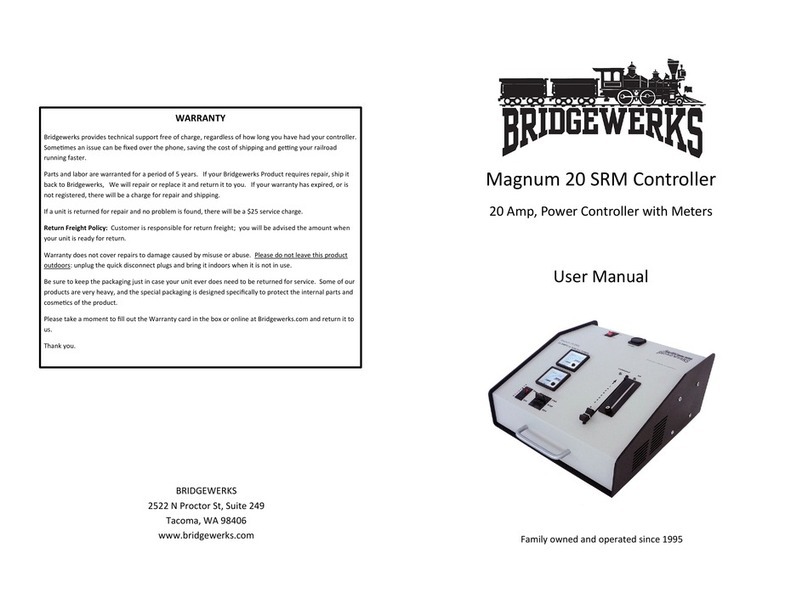
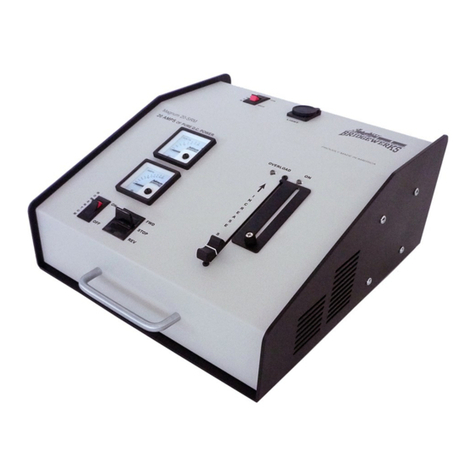
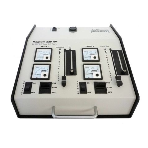
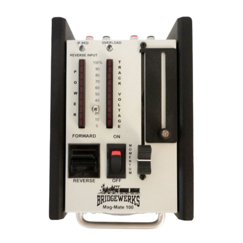
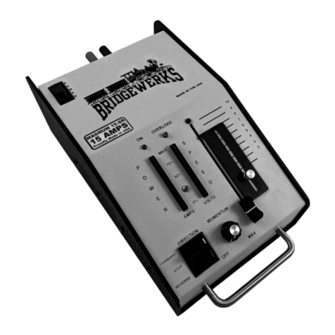
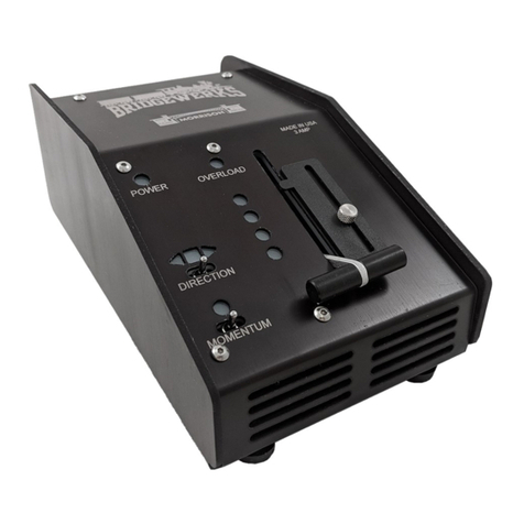
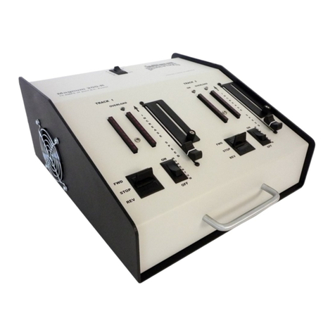
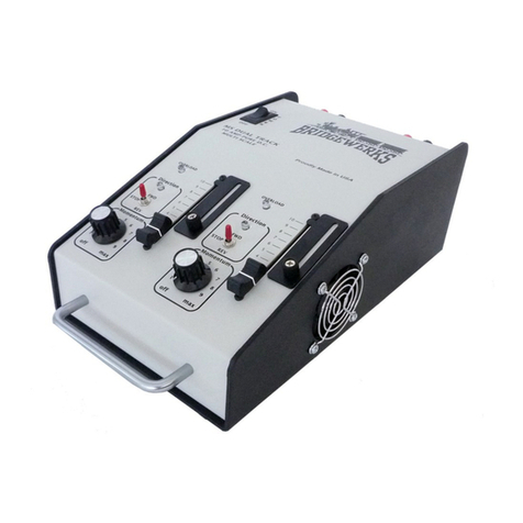
Magnum 4000 Features
• Connecons:
The on/o switch is located in the centre, on the top of the controller. On the rear panel, there are
four sets of outputs, with each set containing a power output to be connected to the track, an accessory
power output, and a pair of yellow terminals for use by Bridgewerks remote control products. The track
outputs connect to each track using one of the banana plugs included. The jacks and plugs are color
coded black (- negave) and red (+ posive) voltage. One of the features of Bridgewerks controllers is
the ability to piggyback the jacks when you have very long track and want to have addional wire
connected at several points on your layout. This gives you maximum evenly distributed power on your
track. The 24-30 volt DC outputs in each secon of the rear panel can be used for accessories.
• Speed Governor:
Bridgewerks’ exclusive “speed-stop” can be used as a safety device to limit the maximum speed of your
trains. The speed stop consists of a metal plate which is held in place with a thumb screw. To adjust the
speed stop, loosen the thumb screw, adjust the throle slide control so that the train is going as fast as
you want to allow, and then slide the speed stop down to limit the maximum speed. Tighten the thumb
screw Now you can move the throle control from 0 up to the maximum selected speed.
• Momentum:
The 4000 features an adjustable momentum control for each track that will limit the acceleraon and
deceleraon of the trains. When momentum is at maximum and you move the throle from the mini-
mum to the maximum, the train will slowly accelerate from a stop to the maximum speed. Similarly if the
throle is moved quickly from maximum to 0, the train will slowly decelerate to a stop. Momentum
adds another dimension of realism to your model railroad. In addion, the combinaon of speed gover-
nor and momentum makes it easier to limit derailments when younger engineers or less experienced
operators are at the controls.
• Direcon Control:
The 4000 has a direcon control switch for each track which will change the direcon of the locomove.
If the locomove runs backwards when the switch is in the forward posion, reverse the connecons
going to the track. Most locomoves will move forward when the + (posive ) terminal is connected to
the rail on the right side of the locomove.
• Overload Protecon:
In the event of an overload, the 4000 has two dierent ways of protecng itself and your train from
damage. There are two manual circuit breakers is on the rear panel. One of these is for tracks 1 & 2, and
the other for tracks 3 & 4. The buon will pop out and the power to the track will be cut o. If this
happens, correct whatever caused the overload, wait 2 or 3 minutes and then push the switch to reset it.
In addion, there is an automac thermal cuto inside the controller which will be acvated in the event
of an overload. This will reset itself automacally in 2-3 minutes aer the cause of the overload is re-
moved.
• Oponal Remote Throle Capability (RC-100):
On the back of the 4000 there are four pairs of yellow terminals for the remote control. Plug the receiver
into these two yellow terminals (it will automacally also plug into the accessory power pins) to provide
you with wireless remote control over the throle
• Wire:
Use heavy gauge wire to connect your power controller to the track. For distances of up to 15 feet,
you should use 12 gauge wire. For distances over 15 , you use 10 gauge wire. Although the track
itself is similar to a very heavy gauge wire, in larger layouts, signicant loss can occur from the
connecons between secons of track. To improve this, run mulple power connecons to the
track from the controller and/or use track clamps rather than slider type couplers. In outdoor
layouts which are exposed to extreme temperatures, the track will expand and contract as the
temperature changes, and slider type couplers may have to be used.
• Outdoor operaon
Garden railways are oen installed outdoors and Bridgewerks controllers are built to be used with
outdoor railroad layouts. However, they are not waterproof, and as with any electronic equipment,
they should not be le outdoors when not in use. To make this easy, the connecons are all made so
that they can simply be unplugged and the controller can be carried indoors.
• Accessory Power
On the back of the 4000, in addion to the pair of yellow remote terminals and the terminals that pro-
vide power to the track, there are four pairs of terminals for accessory power. The pair on the top
provide an unregulated DC power source that will be from 24 to 32V depending on how much power
you are drawing from the connecon.
