Bright Technology cb958b User manual

I

II
TABLE OF CONTENTS
1. Preface----------------------------------------------------------------------------------------------------------------------------------------1
NAMEPLATE --------------------------------------------------------------------------------------------------------------------------------------1
WARNING -----------------------------------------------------------------------------------------------------------------------------------------1
INTRODUCTION ---------------------------------------------------------------------------------------------------------------------------------1
INSTALLATION -----------------------------------------------------------------------------------------------------------------------------------2
SAFETY REGULATION---------------------------------------------------------------------------------------------------------------------------------------2
2.CB958 BALANCE INSTALLATION & OPERATION MANUAL -----------------------------------------------------------------3
2.1PROTECTIVE COVER ASSEMBLY -------------------------------------------------------------------------------------------------------3
2.2BALANCE SHAFT ASSEMBLY -------------------------------------------------------------------------------------------------------------4
2.3 EQUIPPING POWER SOURCE -----------------------------------------------------------------------------------------------------------4
3 .CB958SERIES WHEEL BALANCER TECHNICAL PERFORMANCE -----------------------------------------------------------------4
3.1PERORMANCE & CHARACTERISTIC ----------------------------------------------------------------------------------------------------4
3.2MAIN TECHNICAL SPECIFICATION -------------------------------------------------------------------------------------------------------4
3.3WORKING PRINCIPLE ----------------------------------------------------------------------------------------------------------------------5
4. TRANSPORTATION & INSTALLATION-----------------------------------------------------------------------------------------------5
4.1TRANSPORTATION------------------------------------------------------------------------------------------------------------------------5
4.2INSTALLATION -----------------------------------------------------------------------------------------------------------------------------5
5. SAFETY PRECAUTIONS ----------------------------------------------------------------------------------------------------------------6
6. CONFIGURATION & USE-----------------------------------------------------------------------------------------------------------------7
6.1 CONFIGURATION ------------------------------------------------------------------------------------------------------------------------7
6.2 DISPLAY PANEL -----------------------------------------------------------------------------------------------------------------------------8
6.3 BASIC OPERATION-----------------------------------------------------------------------------------------------------------------------9
6.4 VALUE INPUT-----------------------------------------------------------------------------------------------------------------------------10
6.5 RESIDUAL UNBALANCE VALUE DISPLAY---------------------------------------------------------------------------------------11
6.6 BALANCE MODE & ALU BALANCE MODE SELECT--------------------------------------------------------------------------11
6.7 SUPPLEMENTARY EXPLANATION -----------------------------------------------------------------------------------------------13
7. PROGRAM SETUP-----------------------------------------------------------------------------------------------------------------------14
7.1PROGRAM FUNCTION INTRODUCTION-----------------------------------------------------------------------------------------14
7.2ERROR--------------------------------------------------------------------------------------------------------------------------------------16

III
7.3 PRESS SENSOR INSTALLATION AND WIRING --------------------------------------------------------------------------------------16
7.4 GENERAL TROUBLESHOOTING & SOLUTION -------------------------------------------------------------------------------18
7.5 STANDARD ACCESSORIES -----------------------------------------------------------------------------------------------------------19
8. MAINTENANCE----------------------------------------------------------------------------------------------------------------------------20
9. OPERATION DETAILED DESCRIPTION-------------------------------------------------------------------------------------------23
HOW TO BALANCE A WHEEL------------------------------------------------------------------------------------------------------------23
APPENDIX 1 LAYOUT OFTHE POWER SUPPLY CARD--------------------------------------------------------------------------24
APPENDIX 2 WIRING DIAGRAM---------------------------------------------------------------------------------------------------------25

1
1. PREFACE
WARNING
During this period, the manufacturer will repair or
replace the parts returned or the machine itself,
sustaining the costs but not accepting responsibility for
normal wear and tear, incorrect use or transportation,
or failure to carry out maintenance. The manufacturer
will not inform the customer about any improvements to
the products or the upgrading of the production line.
INTRODUCTION
The purpose of this manual is to provide the owner and
operator of this machine with a set of safe and practical
instructions for the use and maintenance of the wheel
balancer. If such instructions are carefully followed, the
machine will offer you the levels of efficiency and
duration.
The following paragraphs define the levels of danger
regarding the machine.
DANGER: Refers to immediate danger with the risk of
serious injury or death.
WARNING: Dangers or unsafe procedures that can
cause serious injury or death.
ATTENTION: Dangers or unsafe procedures that can
cause minor injuries or damage to property.
Read these instructions carefully before using the
machine. Keep this manual and the illustrated materials
supplied with the equipment in a folder near the place
of operation so as to allow the machine operators to
consult the documentation at any time.
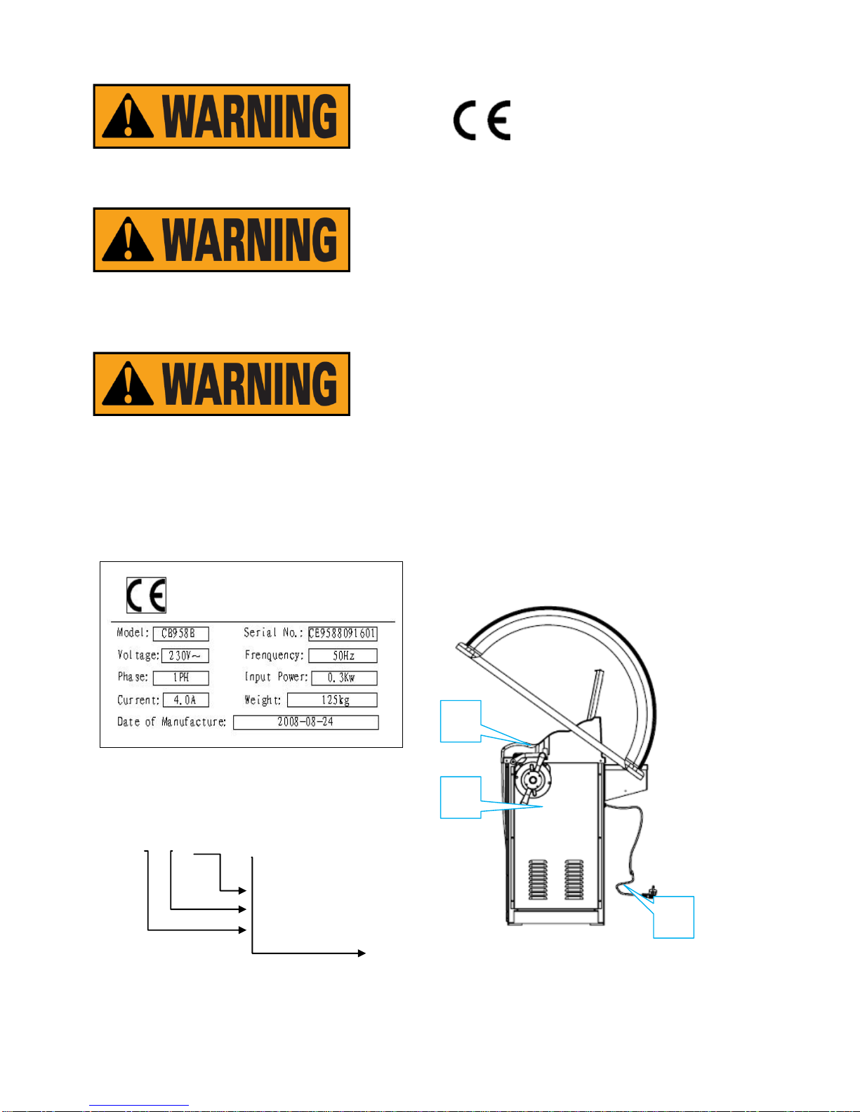
The manual is only to be considered valid for the
machine serial number and model stated on the
attached nameplate.
The instructions and information described in this
manual must always be complied with: the operator will
be held responsible for any operation not specially
described and authorized in this manual.
Some of the illustrations contained in this booklet have
been taken from pictures of prototypes: standard
production machines may differ slightly in certain
respects. These instructions are for the attention of
personnel with basic mechanical skills. We have
therefore condensed the descriptions of each operation
by omitting detailed instructions regarding, for example,
how to loosen or tighten the fixing devices. Do not
attempt to perform operations unless properly quailed
or with suitable experience. If necessary, please
contact an authorized Service Centre for assistance.
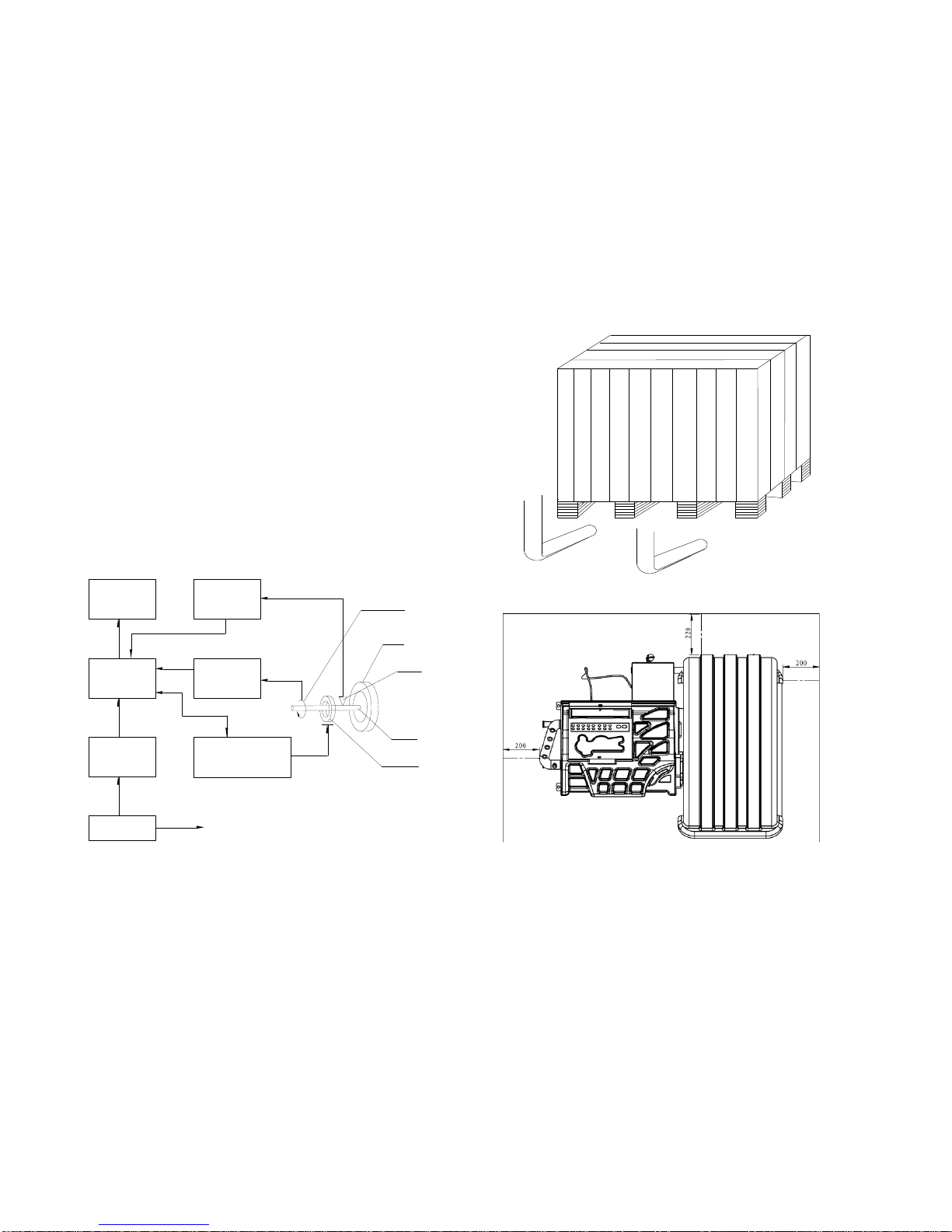
INSTALLATION
Take the utmost care when unpacking, assembling,
lifting and setting up the machine as indicated below.
Failure to observe these instructions can damage the
machine and compromise the operator's safety.
Remove the original packing materials after positioning
them as indicated on the packaging.
All regulations in force concerning safety at work must
be complied with when choosing the installation

2
position. In particular, the machine must only be
installed and operated in protected environments
where there is no risk of exposure to water or liquids.
IMPORTANT: for the correct and safe operation of the
machine, the lighting level in the place of use should be
at least 300 lux.
Environmental operating conditions must comply with
the following requirements:
- relative humidity ranging from 30% to 80% (without
condensation);
- temperatures ranging from 0°to +50°C.
The floor must be strong enough to support a load
equal to the weight of the equipment plus the maximum
load allowed.
The machine must not be operated in potentially
explosive atmospheres.
SAFETY REGULATIONS
Failure to comply with the instructions and danger
warnings can cause serious injuries to the operator or
other persons.
Do not operate the machine until you have read and
understood all the danger/warning notices in this
manual.
The correct use of this machine requires a qualified and
authorized operator. This operator must be able to
understand the manufacturer's written instructions, be
suitably trained and be familiar with the safety
procedures and regulations. Operators are forbidden to
use the machine under the influence of alcohol or drugs
that could affect his/her physical and mental capacity.
The following conditions are essential:
-read and understand the information and instructions
described in this manual;
- have a thorough knowledge of the features and
characteristics of the machine;
-keep unauthorized persons well clear of the working
area;
- make sure that the machine has been installed in
compliance with all relevant standards and regulations
in force;
- make sure that all machine operators are suitably
trained, that they are capable of using the machine
correctly and safely and that they are adequately
supervised during work;
- do not touch power lines or the inside of electric
motors or any other electrical equipment before making
sure that they have been powered off;
- read this booklet carefully and learn how to use the
machine correctly and safely;
- always keep this user manual in a place where it can
be readily consulted and do not fail to refer to it.
Do not remove or deface the DANGER, CAUTION,
WARNING or INSTRUCTION decals. Replace any
missing or illegible decals. If any decals have become
detached or damaged, it is possible to obtain them from
your nearest reseller.
-Observe the unified industrial accident prevention
regulations relating to high voltages and rotating
machinery whenever the machine is in use or being
serviced.

3
- Any unauthorized changes or modifications made to
the machine automatically release the manufacturer
from any liability in the case of damage or accidents
resulting from such changes or modifications.
Meaning of the decals (including the one indicating
caution) Lightning symbol This decal, positioned
on the back of the machine, indicates
where to insert the power supply cable
and warns the user to pay attention to
his safety.
Warning for rotating machine part This
decal, positioned next to the balancing
shaft, reminds the user that this is a
rotating part and is
therefore dangerous and should not be
touched with the hands. The arrow
indicates the rotation direction.
Grounding symbol This decal, positioned
on the back of the machine, indicates
where to insert the power supply cable and
warns the user to pay attention to his
safety
2. INSTALLATION & OPERATION
Before installation and use of the wheel balancer, you
should carefully read this installation and operation
manual. The manual should be kept for future
reference. Operators should be familiar with this
instruction manual to ensure correct operation and
safety.
ATTENTION:
WEAR PROTECTIVE GLOVE
READ OPERATION MANUAL
WEAR PROTECTIVE GLASSES
POWER OFF THE ELECTRICAL
SOURCE OF THE MACHINE
DURING MAINTANCE
2.1 PROTECTIVE COVER INSTALLATION
Before operating the machine, please connect the
protective hood by following the indication
Of the Fig1 if you need to install the protective hood.
Spring
Screw M10X25
Screw M10X35

4
As shown of the above figure, slip the protective cover
into the protective cover support tubeand insert the
socket head screw M10X50. And then lock the
locknut along the reverse direction and loose the 2
hexagon nut to tight the socket head screw.,This can
prevent the protective hood from shaking to influence
the test.
2.2 MAIN SHAFT INSTALLATION
MAINSHAFT INSTALLATION:Before installation,
use the ethyl alcohol and compressed air to clean up
the center hole of the shaft and connect part. Use
spanner and screw to fix the thread shaft on the
balance shaft (Fig2)
2.3 EQUIPPED WITH POWER SUPPLY
ATTENTION! According to the label on the connect
between power cable and body, the power cable
connect socket must be grounded with the reliable
earth wire.
All the electrical devices installation must be done by
the qualified staff. Before installation, please check If
the power system is comply with the technical
parameter marked on the nameplate of the machine.
The wiring of the machine must have the fuse and the
perfect ground protection. And install the electrical
Leakage automatic controls switch in the power
source. And recommend the application of the
stabilizer if the voltage of installation site is unstable.
WARNING
Any electrical connect in the workshop is only done by
the qualified technical staffs and it should meet the
enforced regulation. .
Any electrical connect must be according to the
following:
• Power on the data plate on the machine;
• Voltage decrease can not exceed 4% of the rated
voltage on the data plate when full load (10% when
start)
-Operators must:
• Install the plug;
• install 30ma circuit breaker;
• install power cable fuse;
• provide with effective workshop electrical connect to
ground;
- prevent the authorized operation and pull out the plug
to prolong the working life when not use the machine.
- if the machine directly connected to the power source
through the power board not the plug, we should use
the qualified staffs to operate.
3. ⅢCB958 WHEEL BALANCER
TECHNICAL CHARACTERISTIC
3.1CHARACTERSIC:
-adopts quality computer with the feature of high
intelligence and high stable
-mechanical main shaft adopts high precision bearing
driven, wear-resistant, low noise
-press stop key to realize the emergency stop
-full automatic dynamic/static balance check
-balance 3 ALU rim and 1 motorcycle tire
-self-calibration and full automatic trouble diagnosis
3.2MAIN TECHNICAL SPECIFICATION
-rated voltage 230V 60HZ
-power 250W
-speed 7S(when wheel is about 20Kg)
-accuracy 1g
FIG2

5
FIG4
-noise ≤69dB
-rim diameter 10″~30″
-maximum wheel weight75kg
-rim width 1.5~20″
-net weight 155 kg
-max wheel diameter 47inch
-working environment:temperature 0℃-50℃,RH:
30% —80% (no condense);
3.3 WORK PRINCIPLE
The micro CPU will provide the normal information if it
checks each unit in the normal situation. And the
operators can execute the balance operation. When
balancing, MCPU can control the rotation of the
balancer tester main shaft through the drive interface.
The unbalance signal sensed by balance sensor is sent
to the micro-processor port through A/D converter. CPU
will integrated analyze the unbalance signal and angle
signal to calculate the unbalance value and display the
value through the LED unit. We can realize the
man-machine talk through keyboard and LED.
FIG 3 CB958 WHEEL BALANCER WORK PRINCIPLE
4. INSTALLATION &
TRANSPORTATION
4.1 TRANSPORTATION
-Place, carry and store the machine according to the
indication of the label on the package carton.
-Store environment: RH20%-95%
temperature-10℃-+60℃
-When transport and use the machine, do not pull the
rotation shaft, or it will cause the permanent damage.
4.1.1 After being sure that the package of your machine
is perfect, you can carry the wheel balancer to the
installation site.(Fig4). The choice of the installation
should comply with the following requirements. The
ambient temperature is 0℃-50℃and the RH ≤85%. And
the installation site as shown in Fig5
4.1.2 Remove all packaging and check contents with
below list of items. If any parts missing or damaged,
please contact your distributor.
Packing material such as plastic, Polystyrene, nail,
screw, timber and carton must be placed
into a scrap box and be handled in accordance to the
local regulation and law.
4.2 INSTALLATION
L E D
DISPLAY
MCPU
KEY INPUT
UNIT
POWER UNIT
BALANCE SENSOR
A/D CONVERTER
ANGLE SPEED
TEST CONTROL
INTERFACE
MAINSHAFT ROTATION
DRIVE INTERFACE
ANGLE SPEED
SENSOR
TIRE
BALANCE SENSOR
MAINSHAFT
MAINSHAFT DRIVE
Fig5

6
Position the wheel balancer in the desired position for
use. It must be ensured the floor is
leveled and of solid construction. The wheel balancer is
designed for operation indoors and should
not be exposed to moisture or direct sunlight.
5. SAFETY PRECAUTIONS
5.1.1 Before operation, ensure you have read the
instruction manual and all warning labels. Not working
in accordance with the safety instructions should cause
serious injury or death to the operator or bystanders.
5.1.2 Keep hands removed and loose clothing and
jewelry and stand clear of all moving parts of the
machine when in use. Inspect the machine before use
for any damage. In the event of any damage, the
machine must not be used
5.1.3 In the event of the emergency, you should press
the ―STOP‖ button immediately. To prevent injury, it
must ensure the protective cover is fitted all time.
5.1.4 Before balancing, operators should check all the
tyres and wheels for possible defects. Do not balance
the tyres and wheels with fault.
5.1.5 Do not attempt to balance the wheel if it is to be
found to be defect in any way.
5.1.6 You should wear properly, such as glove, goggle
and working suit. You should not wear necktie, long hair
and loosen clothing. The operator should stand beside
the machine and the unauthorized person should be
kept away from the machine.
5.1.7Before balancing, you should ensure the mount of
the wheel is proper. Before you start rotating the wheel,
you should confirm the quick nut turn around the thread
shaft for less than 4turns and is firmly fixed on the main
shaft.
GENERAL CONDITIONS OF USE
The wheel balancers described in this manual must be
used exclusively to measure the extent and position of
car wheel unbalances, within the limits
specified in the technical data section. Furthermore,
models equipped with motors must be
provided with a suitable guard.
Any use other than those described in this manual is to
be considered improper and unreasonable.
Do not start the machine without the wheel locking
equipment.
Protective
cover plays the role of prevention and safety.。
Do not
clean or wash the wheels mounted on the machine with
compressed air or jets of water.
Get to know your machine. The best way to prevent
accidents and obtain top performance from the
machine is to ensure that all operators know how the
machine works.

7
Learn the function and location of all the controls.
Carefully check that all controls on the machine are
working properly.
The machine must be installed properly, operated
correctly and serviced regularly in order to prevent
accidents and injuries.
NAMEPLATE
Note: The nameplate is stuck in the center to the
top on the rear of the machine.
C B 9 5 8 B
With protective cover
Model
Balancer
Wheel
B. CE mark indicates that this model of
machine has CE certification.
C. SERIES NUMBER: The first 3 digital is
the abbreviation of the model of the
machine and the middle 4 is the
production date and the last 4 is the
product series number.
D. The content on the transverse line
include the name and address of the
company. The contents below the
transverse line includes the rated
electrical parameters of the machine
such as voltage, frequency, power,
phase and full load electrical current
and the weight and the production
date of the machine.
6. CONFIGURATION & USE
6.1 CONFIGURATION
1
2
3

8
1. Power plug 2. Front Panel
3.A-sale 4.Control Panel
5.Weight Tray 6.Protective Cover
7. Quick Nut 8.Balance Shaft
9.Body 10. Power source switch
11. Hinging handle
6.2 DISPLAY PANEL & CONTROL PANEL
6.2.1 DISPLAY PANEL
In the state of parameter input, it is
input key for the distance from wheel
to the wheel balancer. You can change
the distance set value of the window
by press the up/down key. The default
unit is mm.
When use the automatic scale, it is no
need for you to use this key and the
machine will automatically access the
distance from the machine to the tire.
In the state of parameter input, it is the
input key of the breadth of the rim.
The default unit is inch
In the state of parameter input, it is the
diameter of the rim input key. You can
change the rim diameter set value of
the window by press the up/down key.
The default unit is inch.
When use the automatic scale, it is no
need for you to use this key and the
machine will automatically access the
diameter of the rim.
STA/DYN conversion key: The default
boot mode is the standard dynamic
balance. If you need to adopt the
static balance, you can press this key
to operate.
ALU mode. Press this key one by one
to realize the choice of the ALU1
\ALU2\ALU3 standard aluminum alloy
mode.
Self definite ALU mode. If cooperate
with the automatic measure scale,
you can realize the stick of the weight
to the self definite position.
Split weight: After you select the self
definite ALU mode, you can realize
the split of the weight. When the
position of the weight is between the
two spokes, you can hide the weight
4
5
6
7
8
9
10
11
Inside unbalance value
display
Inside unbalance
value
display
Outside unbalance value
display
Balance mode
mode selection
rim breadth
display
im diameter
display
distance display
customer mode select

9
behind between the two spokes.
OPT: When you choose this function,
you can realize the optimum of the
rim, wheel and tire.
MOT\CAR\BUS tire mode selection:
to choose it in accordance of the
type of the tire.
MOT to balance of the motorcycle tire
CAR to balance of the common tire
BUS to balance of the heavy duty tire
to realize the function of speed
reduction and high efficiency.
Residual unbalance value select key:
Select this button to display the
outside/inside residual unbalance
value
mm/inch conversion key for the
diameter and breadth of the tire.
Gr/Oz Unbalance value conversion
key
1、program entrance key for
entering into the program setup
function
2、confirm key for confirming the
input result
press key to stop the machine
press key to start the machine
6.3 BASIC OPERATION
6.3.1 Switch on the main switch on the left side of the
machine,the display will display ―CB-953‖ and then ―0‖、
―0‖(it will display ―0.00‖, ―0.00‖ in ounce state)
6.3.2 MOUNT WHEEL Preparation before test:
Check and clean the dust and mud and if there are
foreign bodies, such as metal, stone, clipped weights
on the surface of the tyre or wheel. And also check the
air pressure of the tyre is according with the specified
value. Check if there are deformation on the rim
positioning surface and installation hole. Check if there
are any foreign bodies in the tyre. Take off the original
weight.
The installation methods of the wheel:Positive
positioning, negative positioning & flange disk. You can
select different methods according to the practice.
6.3.2.1 SMALL CAR WHEEL POSITIVE POSITION
Positive positioning is the normal method. It is featured
with simple and quick operation. It is mainly suitable to
the common steel rim and aluminum alloy rim with
small deformation.
Main shaft wheel(direction of the rim installation
surface is inside)cone quick nut
6.3.2.2 SMALL CAR WHEEL NEGATIVE POSITION
Main shaft spring cone wheel
bowl quick nut
When the deformation of the outside of the wheel,
adopt this method to positioning to grantee the
accurate positioning of the steel rim inner hole and
main shaft.
suitable to the steel rim, especially the thick ALU
The choice on the cone should be adapted to the rim

10
center hole
and pay attention to its direction. Or it will cause the
inaccurate
measurement.
6.3.2.3LARGE FLANGE DISK POSITION(OPTIONAL)
This position is adapted to the mount of the large tire.
Main shaft large flange plate(fixed on the
main shaft)wheel cone quick nut
Note:The choice on the cone should be adapted to the
rim center hole and pay attention to its direction. Or it
will cause the inaccurate measurement.
6.4 INPUT VALUE
6.4.1 Input Distance
Pull the Dis scale to the position stuck
on the rim. Press the key to input the Di value into the
display. At this moment, the display will display ―Dis‖:
―XXX‖. And we can also adjust this value by rotating the
tyre fixed on the main shaft.
When use the automatic scale, the distance from the
machine frame to the tire can be accessed
by the automatic scale. To reach the measurement
accuracy, you must execute a self-calibration
before operation.
6.4.2 Input (Br) eadth Value
Use the Br caliper of the accessories to measure the
breadth of the rim. Press the key to input the Br value
into the display. And now the display will display ―Br‖:
―XXX‖. And we can also adjust this value by rotating
the tyre fixed on the main shaft.
6.4.3 Input the Tire Diameter Value(Dia)
After confirming the rim diameter, press the key to input
the rim diameter into the display. At this moment, the
display will display ―Dia‖:―XXX‖,And we can also adjust
this value by rotating the tire fixed on the main shaft in
this process we should open this function. The machine
can automatically access the diameter of the rim
tested.
Note:When you balance the tire with the relative larger
diameter(DIA>23‖ ),you can adopt long scale to
automatically measure. It is very conveniently.
The detailed measurement methods: Fist pull the scale
to enter the long scale situation and then pull the scale
to the zero position. At this moment, you will hear the
sound of click and then quickly pull the scale to the
measurement position. When the measurement result
is same to the short scale measurement result, using
long scale to measure the tire of larger diameter is
more convenient.
6.4.4 UNIT CONVERSION SELECTION:
①The unit conversion of the Br of the rim from
inch to mm:
Normally, the display of Br should be in inch. When you
need the unit of the display to be mm, you can use the

11
key to realize the unit conversion from inch to mm.
②The unit conversion of the D of the rim from inch to
mm:
Normally, the display of D should be in inch. When you
need the unit of the display to be mm, you can use the
key to realize the unit conversion from inch to mm.
After unit conversion, the unit of the display values of
rim Br and D are , but when you switch off and then on
the wheel balancer, the unit will be still inch.
③The unit conversion from gram to ounce:
Normally, the unit of the unbalance value is gram (g). If
you want to make the ounce(Oz) to be the unit, you can
execute the g/Oz conversion. The unit of the displayed
unbalance value is gram(g). The way to realize the unit
conversion from gram to ounce is to press .
6.4.5 When press the start key ,wheel
balancer starts to run. A few seconds later, the
machine automatically stop. The machine can also
automatically start by lowering down the protective
cover which can be setup by the program.
6.4.6 DISPLAY UNBALANCE VALUE
When the spin ends, the display will display the inner
and outside value of the rim.
Use your hand to pull the wheel. When all the
positioning lamps light inside and outside light, the
weight adding position will be indicated.
6.4.7 Rotate the wheel, when the left side positioning
lamp all light, at this moment, the highest position is the
inner unbalance position and when the right side
positioning lamp all light, at this moment, the highest
position is the outer unbalance position.
6.4.8 Add the corresponding weight at the unbalance
point and start test again until the balance of the tyre.
CAUTION!
1. When start the machine, use hand to pull the wheel
to help it start rotation, especially to the relative bigger
tyre, to prolong the working life of the motor.
2. Check if there are any mistakes on the dimension.
3. Check if the balance methods meet the configuration
of the rim and select the balancer most easily to
balance.
4. Check if the contract nut tight or not.
5. When the balance ends, remove the tyre. Pay
attention to handle it with gentle and avoid knocking the
main shaft.
6. When clipping the weight. Use the hammer to clip
the weight on the rim without too much force. Place on
the ground and knock and do not knock when it is on
the main shaft to avoid damaging the sensor. The
position to add the weight must be without the grease
and dry.
6.5 UNBALANCE VALUE DISPLAY RESIDUAL
The minimum value of the standard weight is 5g so if
the weight you use is less than 5 g, the wheel balancer
will not display the value and only displays the state of
―00‖. When you need to display the residual unbalance
value, you should press ,and the display will
immediately display the inside or outside unbalance
value of less than 5g. The maximum residual
unbalance value is 4 g.
6.6 BALANCE MODE SELECT
Select the balance mode according to the weight dding
position and the balance mode. Press the
Corresponding key to select the balance mode.
When you switch on the machine the machine will
automatic enter into the dynamic balance mode and no
need to select.
Note color to indicate the modified position of the

12
weight
DYNAMIC—clip the weight on both sides
of rim(dynamic balance test once start)
STATIC—Stick weight in centre
STATIC—optional for balancing the
motorcycle When balancing motorcycle wheels, you
require the (optional) motorcycle adaptor accessory
MJ-II. With the assistance of the extension scale, to
measure Di, Br and Di. Input the measure value into the
Di, Br and Di display window. The input method is
similar to the parameter input of the car.. When we
balance the motorcycle tyre, we do not select the MOT
function if the present scale can measure the value of
dis. And if the present scale can not measure the value
of dis, we need the extension scale to execute the
dynamic balance. First we should select MOT and then
input the parameter to execute the dynamic balance.
ALU1-to balance light aluminum alloy rim
by sticking the weight on the shoulder of the rim.
ALU1
Dis1=Dis + ”
Br*=Br-1 ”
Dia1=Dia2=Dia-1”
ALU2-to balance light aluminum alloy rim by hiding
the weight inside.
Dis1=a+ ‖
Br*=Dis from O point to the outside of the
flange disk -‖ -Dis
Dia1=Dia-1‖ Dia2=Dia -2 ‖
ALU3-Click the weight inside and stick
the weight outside(outside position is
similar to ALU2)
3/4”
”
3/4”
1/2”
1/2”
3/4”
1/2”
11/4”

13
Dis1=Dis
Dis2= Dis from O point to the outside of the flange
disk-‖
Dia1=Dia
Dia2=Dia-2 ‖
ALU4-Click the weight inside and stick the
weight outside(outside position is similar to
ALU2)
Dis1=Dis
Dis2=Dis + ‖
Dia1=Dia
Dia2=Dia-1‖
6.7 ALU* SELF DEFINITION METHOD AND
WEIGHT SPLIT FUNCTION ALU*
When the customer select the self definition ALU
modes , first use the scale to measure the inside
position of the self-definition weight and then hen press
key to confirm. At this moment, the display will
display the dimension at the D1 position. And then use
the scale to measure the inside position of the
self-definition weight. When we hear the sound of tick,
Meanwhile, the display will display the dimension at the
D2 position. On this condition, we complete the
measurement. Press start key to start up the machine.
After the machine stops rotating, the display displays
the inside and outside unbalance value. Rotate the
wheel until the entire inside position indication lamps
light up. At this moment, the D1 lamp will light. Step the
brake to stop the tire. Pull out the scale and the Dis
value will reduce when the length of the scale enlarged.
When pull to the zero position, press the back end of
the scale and the seal will mark a weight position. In a
similar way, when the entire outer indication lamp light,
mark a weight stick position and stick the
corresponding weight and rotate the wheel to test and
the self-definition ALU mode complete.
ALU SELF-DEFINATION BALANCE MODE :
You can hide the weight behind the spoke. Thisis
only applied to the outside weight.
The detailed operation step is :
6.7.1、After complete the self-definition ALU mode,
first stick the weight inside and select key.
The display will display ―SP‖ –―5‖. According to the
actual spoke quantity, press to adjust to
the actual quantity of the spoke to clip the weight and
then press to confirm.
2 Position any bar of the spoke to the 12clock and hold
on and press
21/2
”
11/4”

14
to confirm.
6.7SUPPLEMENTARY EXPLAINATION:
Once switching on, you will see standard dynamic
balance mode setup by the computer. When selecting
ALU mode and the configuration of the aluminum alloy
rim is similar to the above standard ALU1\ALU2\ALU3,
you can get relative accurate balance effect. If the
section of the tire similar to the one given be the
program, you need do some adjustment on the position
and weight of the weight. General speaking, 1~2 times
of adjustment can reach relative satisfactory balance
effect.
7 PROGRAM SETUP
7.1 PROGRAM FUNCTION INTRODUCTION
Press program key to enter the program setup
menu.
7.1.1 [SET] –[OPT]-[ ] (unbalance value optimum
calibration):Press key to confirm the entrance.
Select up and down key to adjust the
unbalance threshed value. You can choose from
15Gr-100Gr and press key to confirm when you
choose the corresponding value.. Press key to
enter the next function setup level.
7.1.2 [SET] –[p]-[ ] (protective hood setup) Once
again press to confirm the entrance. Select
up/down key to ON/OFF setup the protective
hood function and ten press key to return.
7.1.3 [SET]-[SP]-[ ] (protective hood control )
Select to enter and then press key
To confirm the entrance and the setup is similar to the
above.
7.1.4 [SET]-[APP]-[ ]-( light tire minimum
unbalance setup) You can setup 1Gr and 5Gr. The
setup is similar to the above.
7.1.5
7.1.6 [SET]-[BIP]-[ ] (beeper setup) You can setup
the on/off of the beeper.
7.1.7 [SET]-[Rl1]-[ ] (set up if the automatic scale
Dis -to the machine- input automatic or not) You can
choose on or off.
7.1.8 [SET]-[Rl2]-[ ] (set up if the automatic rim
breadth input automatic or not) You can choose on
or off.
7.1.9
7.1.10 [SET]-[PRN]-[ ] ( printer setup switch) You
can select on/off. If select on , you can select printing
When press key to print the balance result.
7.1.11 [SET]- [UP]-[ ] ( enter the next menu of the
programm) Involve the test on the various sensors
and scales and the self-calibration.
7.1.12 [SET]- [UP]Press key to enter into the
special function setup.
[TES] –[INT]- (sensor\scale measurement) It can
separately measure the photocell sensor, piezoelectric
sensor, Dis, Bre and Dis . Through the test, we can
identify the problem.
Press key to enter and the display will display
TES POS (phase sensor). Rotate the tire forward and
backward and the display will display [TES] –[POS]-
[XXX]. If rotate the tire backward, the value of[ XXX] will
increase and if forward, [XXX ]will decrease.
Once again press key to enter [TES]- [STA]
(dynamic test sensor). When service, press the
sensor vertical to the main shaft.

15
You can execute the following step by step:
[TES] [ DYN]( dynamic sensor test)
[TES] [ Dis] (test for the distance to the machine )
[TES] [Dia] (test for the rim diameter)
[TES] [ Wid] (test for the rim breadth)
By testing the above sensors, you can quickly find the
trouble shooting point.
After entering into [SET] [UP], do not enter the [TES]-
[INT] program. Press key, you can enter the
customer weight marking(CAL WEI) You can select this
function when you consider the test result inaccurate or
the machine not used for a long time. When you enter
into this function, display will display[ ADD] –[ ]-[ 0 ]-
and press to start the machine for a time.
(This operation must be executed after mounting the
tire or rim with the relative small unbalance value and
input the correct value of the Dis, Bre and Dia)Or you
will cause the inaccurate measurement result.
When rotate the wheel to test, it will display [ADD]
[ ]–[100]. Rotate the wheel and clip a piece of
standard weight of 100Gr at the top center position
when the entire tire unbalance indicating lamp light.
And start the machine once again, you can realize the
self-calibration. This
operation can make the machine fast restore its use of
precision.
****The shortcuts is located in the operation window not
the program setup window. Press and hold on
key. Five seconds later, the program will automatically
enter the self-calibration program and the display will
display [ADD]-[ ] –[ 0 ]- The other operation steps
are similar to the above.
If need to enter the scale self-calibration, follow the
following steps:
The display will display [CAL]-[WEI]-[CAL] Press
to enter [CAL]- [RL1]-[ ]
Enter the scale calibration program:[CAL]- [RL1]-
[ ](distance to the machine) Press key to
confirm the entrance and the display will display [Dis]
-[ ]-[ 0 ]
Position the scale to the zero position, press to
confirm and the display will display [Dia]-[ ]--[14],
Mount a medium size tire or rim on the main shaft and
then, according to the diameter of the rim and tire
mounted on the shaft, press to adjust the
14to the dimension of the rim mounted(change the
value on the right window from 14 to 16 if the diameter
of the tire mounted is 16‖)and then pull out the scale
end to lean it against the edge of the rim and at the
same time press key to confirm. Thus we have
completed the automatic dis&dia scale calibration.
Ⅱ****The shortcuts is located in the operation window
not the program setup window. Press and hold on
key. Five seconds later, the program will
automatically enter the self-calibration program and the
display will display [ADD]-[ ] –[ 0 ]-. Then press
and the display will display [CAL]—[RL1]-[ ],
The other operation steps are similar to the above.
If need to enter the width scale self-calibrition ,follow
the following steps
The display will display.[CAL]-[RL1]-[ ] Press
to enter [CAL]-[RL2]-[ ] (Cale width ruller)
Press to confirm the entrance and the display will
display [CAL]-[RL2]-[P0],Position the width scale to
the zero position press to confirm and display
will display [CAL]-[RL2]-[P1] ,and Pull out the
width scale end to lean it against the plan of the
mainshaft and at the same time press key to
confirm.
Thus we have completed the automatic widthscale
calibration.

16
The above operation step vector diagram is as
follows:
7.2 ERROR INDICATION:
Attention:When change the computer board, the
phase sensor or the press sensor, you must execute
the self-calibration. When change the computer board,
you should setup the parameter according to the
parameter marked in the machine or on the original
computer board. Repeat the self-calibration after the
modification.
7.3 INSTALLATION AND WIRING OF THE PRESS
SENSOR

18
Sometimes, inaccurate balance or incorrect position is caused by the breakage of the press sensor. The
changing method of the sensor is as following:
(1)Remove the upper cover and the right side panel of the balancer.
(2)Detach the nut1 and 2, elastic washer, plain washer and large flat washer.
(3)Loose the back nut3.4.5 to detach every parts.
(4)Change the new sensors and tight the dual-head screw and then tight nut 5. The installation of the
negative and positive pole of the piezoelectric ceramics disk of the sensor must follow the picture.
(5)Use the spanner to tight the nut4 and then nut 3. At this moment, you should pay attention
to the horizontal and vertical sensor screws should be vertical. And the end of the screws should
be just fallen into the 2 holes.
(6)Mount the nut1 and 2, elastic washer, plain washer and large flat washer and completely tigh them.
Usually, lock nut 1 and then nut 2. We require to flat the elastic washer and then return the nut
1/4—1/2turn. Use this way to get the normal pre-pressure of the press sensor(use torque wrench to lock
and the torque is 40NM)
(7)There are glass glue coat on the surface of the press sensor and the normal installation result
of the piezoelectric ceramics disk of the sensor is the IR should be larger than 50MΩ.
(8)Discharge the output line of the shortcuts press sensor,insert into the computer board after discharge
to avoid the breakage of the computer board.
(9)Insert the vertical(┴)& horizontal(∥)sensor plugs according to the original position.
(10)Calibrate the balancer again and install the upper cover and the side panel after check result is
normal.
7.4 GENERAL TROUBLESHOOTING & SOLUTION:
Description
Cause
Solution
Start the machine
but not display.
1. .Check the circuit of 220V is normal or not.
2. power board fault
3. The cable between the power board and
computer loose
4. computer board fault
1. Check and connect the
external power source.
2. Changer the power board
3. Check the plug cable
4. Change the computer board
Display is normal
but the start button
and input push
button not working.
1. contact switch not good
2. machine breakdown
1. Open the housing of the machine
and plug in and tight the contact
switch plug.
2. Start the machine again
Display is normal
but not braking after
start.
1. The cable between the power board and
computer loose
2. power board fault
1. Plug in and tight the cable
between the computer board and
power board.
Table of contents
Popular Power Tools manuals by other brands

Alpha tools
Alpha tools DF 850 Original operating instructions

VARO
VARO POWERPLUS POWXB40020 manual

Grizzly
Grizzly G8621 parts list

Chicago Pneumatic
Chicago Pneumatic Quiet CP7830Q Operator's manual

FOREDOM
FOREDOM H Series Assembly, operation and service manual

Stahls
Stahls WEEDING TABLE Installation instructions manual