Brightline cMe3 Instruction manual

cMe3
Assembly and Installation Instructions

Fixture Features
•Custom heat sink
•Internal glare control filter
•External soft light diffusion
•Focusing handle
•Articulating light cell
•2.4G RF remote for on/off, dimming and tunable white (2700K to 6500K) control
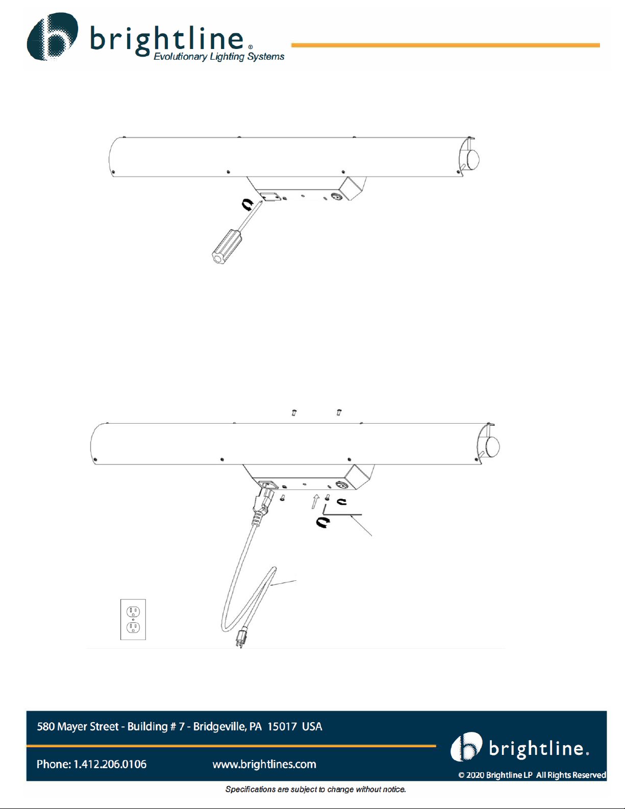
•Hardwire and plug-in power supply options
•120-277V 50/60Hz Input - 42V DC Output @ 0.9A
Construction
•Fixture and canopy base are made from aluminum
•Diffusion plates from PMAA plastic
Fixture Finish
•Powder coat black
LED Technology
•3523 lumen output @ 5000K
•96+ CRI (98 TLCI)
•Color Temperature range from 2700K to 6500K
•Adjustable for seasonal affective disorder (SAD) therapy
•RF remote control with on/off and two touch controls for brightness and color adjustment
Fixture Dimensions and Weight
•Length: 35.4 inches (900 mm)
•Height and Depth: 9.8 inch x 4 inch (203 mm x 102 mm)
•ADA compliant
•Weight: 5.7 lbs. (2.6 kg)
Certifications
•cETL (conforms to UL1598; CSA Std C22.2.250.0)
Specifications

Part
Description
Image
Quantity
A
Main
Housing
with
Diffuser
1
B
Canopy
Back Plate
1
C
Plug-in
Power
Supply
1
D
Diffuser
Allen
Wrench
1
E
Canopy
Allen
Wrench
1
F
Remote
Control
(batteries
not
included)
1
cMe3 Packing List

cMe3 comes fully assembled and ready for installation! Before beginning the installation process, please familiarize
yourself with the fixture and make sure there is no damage to the fixture due to transit. Compare carton contents to
the CMe3 Packing List. If any parts are damaged do not attempt to install the fixture.
cMe3 is fully encapsulated in a protective foam pack and every precaution has been taken to ensure your unit
arrives safely and ready for use; however, damage in shipment can occur. In the unlikely event the Main Body
Housing diffuser is damaged in transit, please notify Brightline and a replacement part will be sent to you. We have
included a diffuser Allen wrench (Part D) to remove the diffuser if required, please keep this Allen wrench in a safe
place for future use if needed.
Unpacking cMe3

cMe3 can be installed by hardwiring direct to a wall junction box with 120V-240V AC circuit OR you can mount
cMe3 to the wall surface and plug into a standard 120V 50/60 Hz three-prong outlet.
WARNING - RISK OF FIRE AND ELECTRICAL SHOCK. FIXTURE MUST BE INSTALLED BY A
QUALIFIED ELECTRICIAN ONLY IN ACCORDANCE WITH NATIONAL, LOCAL BUILDING AND
ELECTRICAL CODES. DISCONNECT POWER AT ELECTRICAL PANEL BEFORE BEGINNING OR
SERVICING.
Junction Box Installation
1. Before beginning any installation, be sure to turn off the power at the service breaker panel. Failure to do
so may result in a fire and electrical shock.
2. Install the Canopy Back Plate (B) directly to the wall mounted junction box as shown –junction box
mounting screws are not included. Make sure the Canopy Back Plate is level and secure. Pass the supply
wire from the branch circuit through the Canopy Back Plate for Step 3.
Installation Instructions

3. Connect the Supply Black, Ground and White (L-G-N) wires from the junction box to the terminal
connection box of the cMe3 as shown below.
IMPORTANT: THERE ARE THREE (3) WIRES (SHOWN BELOW) FROM THE MAIN HOUSING CANOPY
THAT CONNECT TO THE PLUG-IN RECEPTACLE AND ARE ONLY USED FOR THE PLUG-IN POWER
SUPPLY INSTALLATION METHOD.
4. Install the Main Housing Canopy to the Canopy Back Plate as shown above. Tuck the supply wires into the
junction box and align the four slotted holes on the Main Housing Canopy with the Canopy Back Plate
holes. Use Canopy Allen Wrench (E) and the four screws provided with the Main Housing Canopy to
secure to the Canopy Back Plate by turning clockwise until tight.
5. Return power to the branch circuit at the service breaker panel and proceed to the section Setting Up Your
cMe3 Remote.
Black / Live
Ground
White / Neutral
Main Housing Canopy
Canopy Screws (4)
Terminal Connection Box
Only used for Plug-In
Power Supply Installation

Plug-In Power Supply Installation
1. Install the Canopy Back Plate (B) to a secure wall surface using an appropriate fastener for the specific
surface type. Because of the various types of installation methods and wall materials, hardware is not
provided for this step. Be sure the method to anchor the Canopy Back Plate (B) is rated to hold cMe3
weight and normal usage. A 120V 50/60 Hz AC 3-prong outlet must be within five feet of the Canopy Back
Plate to ensure a direct connection using the Plug-in Power Supply (C). Make sure the Canopy Back Plate
is level and secure before proceeding to the next step.

2. Cut the three Safety Tabs from the Black, Ground and White (L-G-N) wires that come from the Plug-In
receptacle as shown below –the Safety Tabs are designed to differentiate between the Junction Box and
Plug-In Power Supply installation methods. After cutting the safety tabs clean the wires with a wire
stripping tool or similar to about 3/8” as shown.
3. Connect the Black, Ground and White (L-G-N) wires from the Plug-In receptacle located in the Main Body
Housing to the terminal connection box of the cMe3 as shown below.
3/8”
Black / Live
Ground
White / Neutral

4. Remove the receptable Plug-In cover plate as shown below using a #2 Philips Screwdriver (not included).
5. Install the Main Housing Canopy to the Canopy Back Plate as shown below. Be sure to tuck all wires
neatly into the Main Housing Canopy and align the four slotted holes on the Main Housing Canopy with the
Canopy Back Plate holes. Use Canopy Allen Wrench (E) and the four screws provided with the Main
Housing Canopy to secure to the Canopy Back Plate by turning clockwise until tight.
E
C

Setting Up Your cMe3 Remote
1) Install two type AAA batteries (not included) in the cMe3 Remote (F) and close the back cover. Have the
remote nearby for Steps 2 –4.
2) Once cMe3 is installed and power is going to the fixture, proceed to turn the fixture ON using the round
toggle switch at the bottom of the Main Housing Canopy.
3) Press and hold down the Remote (F) ON button within five (5) seconds of turning ON the Main Power
Toggle Switch.
4) While holding down the remote ON button the cMe3 Light Bar will start to “blink” on and off. Continue to
hold down the ON button through the blinking phase; once the blinking stops the cMe3 remote will be
synchronized to the fixture. It is recommended to leave the cMe3 Main Power Toggle Switch in the ON
position at all times and use the Remote (F) to turn the fixture ON and OFF and utilize the remote dimming
and temperature change functions.
Main Power “ON” Toggle
Switch

Adjusting cMe3
The Articulating Light Bar may be rotated upward or downward to adjust light output direction. Adjustments should
be made using the Light Bar handle on the back of cMe3 as shown below. Never attempt to rotate the Light Bar
using the diffuser or post extensions.

Warranty
Brightline guarantees all its manufactured LED products to be free from defects in materials and workmanship for a
period of three (3) years from the date of shipment.
Procedures
If any product is found to be unsatisfactory under this warranty, the buyer must notify Brightline immediately. Once
a course of action has been determined, if it is necessary to return the product to Brightline a Return Authorization
(RA) will be issued. Ship the product directly to Brightline, 580 Mayer Street, Building #7, Bridgeville, PA 15017.
The RA number should be marked on the shipping carton. The unit will be replaced or put into proper operating
condition, free of all charges. The correction of any defects through repair or replacement by Brightline shall
constitute fulfillment of all obligations and liability of Brightline to the buyer under this warranty and the contract of
sale.
Disclaimers
Brightline is not responsible for damage to its products caused by improper installation, maintenance, or use; by
improper electrical hookups, or by unauthorized repairs.
Failure to notify Brightline of unsatisfactory operation or any improper or unauthorized installation, maintenance,
use, repairs, or adjustments shall terminate the warranty and Brightline shall have no further responsibility under the
warranty. Brightline shall not be liable for special or consequential damages in any claim, action, suit, or
proceeding arising under this warranty or contract of sale, nor shall Brightline be liable for claims for labor, loss of
profits or goodwill, repairs, or other expenses incidental to replacement. Brightline makes no other warranty of any
kind whatsoever, expressed or implied, and all implied warranties of merchantability and fitness for a particular
purpose that exceed the obligation specifically describe in this warranty are hereby disclaimed by Brightline and
excluded from this agreement. All shipments, unless otherwise noted, are F.O.B. factory.
The customer is advised to inspect for shipping damage, apparent and /or hidden. If detected, notify the
transportation company and file your claim.
580 Mayer Street, Building #7, Bridgeville PA 15017 • phone 412.206.0106 • fax 412.206.0146
www.brightlines.com
Table of contents
Other Brightline Lighting Equipment manuals
Popular Lighting Equipment manuals by other brands

Martin
Martin Easypix 300 user manual

Eastwood
Eastwood 32405 instructions

Zafferano
Zafferano SEE YOU Mounting instructions

Knightsbridge
Knightsbridge EMPOWERST Installation & maintenance manual

Spectroline
Spectroline BIB-150P/F/J Series quick start guide

brennenstuhl
brennenstuhl HL DA 61 M3H2 operating instructions