BriskHeat FE-Series User manual

© BriskHeat® Corporation. Tutti i diritti riservati.
76
Cavo scaldante Serie FE Istruzioni di installazione
PN:11467 Rev K
INFORMAZIONI SULLA GARANZIA
BriskHeat assicura la garanzia di questo prodotto all'acquirente originale per il periodo di diciotto (18)
mesi dalla data di spedizione o di dodici (12) mesi dalla data di installazione, a seconda di quale viene
prima. L'obbligo e il rimedio esclusivo da parte di BriskHeat ai sensi della presente garanzia sono limitati
alla riparazione o alla sostituzione, a discrezione di BriskHeat, di qualsiasi parte del prodotto che può
rivelarsi difettosa in condizioni di uso e manutenzione conformi in seguito alla verifica da parte di
BriskHeat e che è determinata difettosa da parte di BriskHeat. I dettagli completi della garanzia si
possono trovare online all'indirizzo www.briskheat.com o contattandoci al numero 1-800-848-7673
(numero verde, Stati Uniti / Canada) o 1-614-294-3376 (tutto il mondo).
Sede aziendale:
4800 Hilton Corporate Dr.
Columbus, OH 43232, Stati Uniti
Numero verde: 800-848-7673
Telefono: 614-294-3376
Fax: 614-294-3807
Email: [email protected]
Europa:
P.O. Box 420124
44275 Dortmund, Germania
FE-Series (FE)
Constant-Wattage Heating Cable
Instruction Manual
Language Page
English ..................................................................................................... 1
Spanish (Español) .................................................................................... 16
French (Français) ..................................................................................... 31
German (Deutsch) .................................................................................... 46
Italian (Italiano) ......................................................................................... 61
English
You must read and understand this manual before installing,
operating, or servicing this product. Failure to understand these
instructions could result in an accident causing serious injury or
death.
Keep these instructions for future reference.

© BriskHeat Corporation. All rights reserved.
2
FE-Series Heating Cable Installation Instructions
TABLE OF CONTENTS
Introduction ........................................................................................................................................... 2
Applications ........................................................................................................................................... 2
Approvals .............................................................................................................................................. 2
Important Safety Instructions ................................................................................................................. 3
Connection/Termination Kits Descriptions ............................................................................................. 4
Prior to Installation ................................................................................................................................ 4
Lead Termination Preparation ............................................................................................................... 5
End Termination Preparation................................................................................................................. 6
Power Input Connection Installation ...................................................................................................... 7
Splice Installation .................................................................................................................................. 8
Heating Cable Installation ..................................................................................................................... 9
Installing Thermal Insulation……………………………………………………………………………………..10
Electrical Insulation Resistance Test…………………………………………………………………………...11
Periodic Inspection Record ................................................................................................................... 11
Maintenance Instructions ...................................................................................................................... 13
Emergency Procedures ......................................................................................................................... 13
Troubleshooting Guide .......................................................................................................................... 14
Warranty Information ............................................................................................................................. 15
INTRODUCTION
Thank you for purchasing a BriskHeat FE series constant-wattage heating cable system. A heating cable
system is a combination of heating cable, connection / termination kits, temperature controller, and
accessories based on your particular application. Your heater is designed to provide a long and efficient
service life with function, reliability, and safety in mind.
All BriskHeat Constant-Wattage Heating Cable utilize a parallel resistance modular design. This allows
the heating cable to be cut to length and terminated in the field, without affecting the heating power per
unit length. The modular design enables the cable terminations / electrical connections to be made with
cold leads and cold ends (e.g. cable not heated in electrical junction box).
A temperature controller is required for all constant-wattage heating cable.
For additional information concerning this, or other BriskHeat products, please contact your local
BriskHeat distributor or contact us toll free (U.S. and Canada) at 1-800-848-7673 or 614-294-3376.
Ordinary Locations
Hazardous Locations
Class I, Division 2, Groups B, C, & D
Class II, Division 2, Groups F & G
Class III, Division 2
Tinned Copper Braid Only
Ordinary Locations
(120 and 230VAC only)
2014 / 35 / EU (Low voltage directive)
IEC 60519-1
2011 / 65 / EU (RoHS 2 directive)
2012/19/EU (WEEE Directive)
Approvals valid only when installed in accordance with all applicable instructions, codes, and regulations.
APPROVALS
Intended Applications:
General Purpose Trace Heating
Pipe/Tank/Vessel Heating
Ordinary and Hazardous Locations
Dry Area Applications
Prohibited Applications:
Outdoor use
Immersion heating
Use on non-metallic fixtures
Wet Area Applications
APPLICATIONS
© BriskHeat® Corporation. Tutti i diritti riservati.
75
Cavo scaldante Serie FE Istruzioni di installazione
NOTA

© BriskHeat® Corporation. Tutti i diritti riservati.
74
Cavo scaldante Serie FE Istruzioni di installazione
GUIDA ALLA RISOLUZIONE DEI PROBLEMI
Si prega di leggere questa guida prima di contattare la BriskHeat®. Questa guida è stata progettata per
rispondere alle domande più frequenti. Se non si riesce a identificare il problema o si ha bisogno di
ulteriore assistenza, si prega di contattare il distributore locale BriskHeat® o contattarci al numero verde
(USA/Canada) 1-800-848-7673 o 614-294-3376 o [email protected].
PROBLEMA SOLUZIONE(I)
L'intero cavo
scaldante non si
riscalda
Verificare se il riscaldatore è collegato alla tensione corretta.
Verificare se c'è una lettura di resistenza (non un circuito aperto) nel
riscaldatore utilizzando un ohmmetro.
Porzione di cavo
scaldante non si
riscalda
Esaminare il modulo non riscaldato se presenta danni.
L'interruttore del
circuito è scattato Assicurarsi che l'interruttore del circuito sia in grado di gestire l'amperaggio
richiesto del riscaldatore.
Accertarsi che non ci siano danni al riscaldatore e al cablaggio.
Verificare se ci sono circuiti aperti tra il filo bus e la treccina da terra.
Assicurarsi che la lunghezza del riscaldatore non superi la lunghezza massima
del circuito (vedere le tabelle seguenti).
Lunghezza massima del circuito
Cavo 120 VAC
ft (m)
208 VAC
ft (m)
240 VAC
ft (m)
277 VAC
ft (m)
480 VAC
ft (m)
3 W/ft (10 W/m) 640 (195) 1110 (338) 1280 (390) N/A 2560 (780)
8 W/ft (26 W/m) 240 (73) 415 (127) 480 (146) 555 (169) 960 (293)
5 W/ft (16 W/m) 385 (117) 665 (203) 770 (234) N/A 1535 (468)
12 W/ft (39 W/m) 160 (49) 277 (85) 320 (98) 370 (113) 640 (195)
© BriskHeat Corporation. All rights reserved.
3
FE-Series Heating Cable Installation Instructions
IMPORTANT SAFETY INSTRUCTIONS
SAFETY ALERT SYMBOL
The symbol above is used to call your attention to instructions concerning your personal safety. It points
out important safety precautions. It means “ATTENTION! Become Alert! Your Personal Safety is
involved!” Read the message that follows and be alert to the possibility of personal injury or death.
Never handle the heater while it is in operation;
always disconnect the heater from the power
source and allow to cool prior to handling.
Inspect heater and connection kits before use.
Never operate heater without a temperature
control device.
Do not wrap the heating cable over itself.
If spillage of a foreign matter onto heater occurs,
disconnect from power source clean after heater is
allowed to cool.
Never operate a heater without an appropriate
heat sink (device being heated is considered a
heat sink).
Do not operate heater above rated temperature
value.
Fasten heater to device using approved methods
only.
Do not repair damaged or faulty heaters.
Do not crush of apply severe physical stress on
heater or cord assembly
Disconnect heater when not in use
Failure to observe these warnings may result in personal
injury or damage to the heater.
Do not immerse heater in liquid.
Heater must be 5/8 in (13 mm) away from any
combustible material.
Use heater only in approved locations.
Keep sharp metal objects away from heater.
Failure to observe these warnings may result in electric
shock, risk of fire, and personal injury.
A person who has not read and understood all operating
instructions is not qualified to operate this product
DANGER
DANGER
Immediate hazards which WILL result in severe personal
injury or death.
Hazards or unsafe practices that COULD result in severe
personal injury or death.
Hazards or unsafe practices that COULD result in minor
personal injury or property damage.
DANGER
WARNING
End-User Must Comply to the Following:
Only qualified personnel are allowed to connect the
electrical wiring.
Disconnect all supply power at the source before
making any heating cable power input connections.
All electrical wiring must follow local electrical
codes and highly recommend following NEC Article
427.
The person who performs the final installation /
wiring must be qualified for this work.
The end-user is responsible for providing a suitable
disconnecting device.
The end-user is responsible for providing suitable
electrical protection device. It is highly
recommended that a ground fault circuit breaker be
used.
Failure to observe these warnings may result in personal
injury or damage to the heater.
WARNING
CAUTION
CAUTION

© BriskHeat Corporation. All rights reserved.
4
FE-Series Heating Cable Installation Instructions
CONNECTION / TERMINATION KIT DESCRIPTIONS
FECABSK:
Splice Kit
3-Lead pouches
1-End pouch
3-Shrink tubes
1-3 oz. Tube RTV sealant
1-Caution label
3-Ring terminals
3-Splice connectors 12-10 AWG
Enough to complete one in-line splice or one
tee splice, three lead terminations and one end
termination.
NOTE: Requires single hub junction box, pipe
standoff, two pipe straps.
FECABLP:
Lead Termination Kit
1-Lead pouch
1-Shrink tube
Enough to complete one lead termination.
FECABEP:
End Termination Kit
1-End pouch
1-Shrink tube
Enough to complete one end termination.
FECABUC:
Universal Connection/Termination Kit
3-Lead pouches
2-End pouches
6-Shrink tubes
1-3 oz. tube RTV sealant
1-Caution label
2-Ring terminals
2-Splice connectors 12-10 AWG
3-Wire nuts
1-1 in NPT Pipe standoff
2-Pipe straps
Enough to complete one power input connection or
one power input splice, three lead terminations and
two end terminations.
NOTE: Requires double hub junction box.
FECABKC:
Lead/ End Termination Kit
5-Lead pouches
5-End pouches
10-Shrink tubes
Enough to complete five lead terminations and five
end terminations.
PRIOR TO INSTALLATION
STEP 1:
Check for suspected damage to heater like rips, punctures, etc. Ensure surface to be heated is free of
jagged or sharp edges or weld splatter.
STEP 2:
Confirm all necessary installation hardware and tools are readily available. Depending on the application
and kit, this may include.
Tools
Diagonal Cutter Crimping Tool / Wire Stripper Heat Gun
Measuring Tape/Ruler Knife Screwdriver
Temperature Controller
Temperature Sensor
Connection / Termination Kits
(see kit descriptions to verify
contents and additional
required hardware)
Insulating Material
Monitor Light Kit (Optional)
RTV Sealant
Pipe Straps
Junction Box 1 in NPT
Wire Nuts
Caution Labels
Aluminum or Fiberglass
Adhesive Tape (verify
temperature rating)
Heat Conductive Putty
Pipe Standoffs 1 in NPT
STEP 3:
(A) Verify the total amperage of the system does not exceed the maximum amperage that the heating
system components can handle. (B) Verify that the total length of cable required does not exceed the
maximum circuit length. If the cable length exceeds (A) or (B), the cable must be divided into sections.
Hardware and Accessories
© BriskHeat® Corporation. Tutti i diritti riservati.
73
Cavo scaldante Serie FE Istruzioni di installazione
Chiunque abbia letto e capito tali istruzioni è qualificato per
mantenere questo riscaldatore.
ISTRUZIONI DI MANUTENZIONE
Manutenzione:
Tutti gli interventi di manutenzione devono essere eseguiti dopo che il riscaldatore viene
raffreddato a temperatura ambiente e con l'elettricità scollegata.
Sporcizia, olio, grasso o altre sostanze estranee possono essere rimosse con un panno umido e
detergenti delicati.
Non tentare di riparare un riscaldatore danneggiato.
Conservazione:
Dieses Produkt sollte bei Raumtemperatur in einer Umgebung mit weniger als 80% relativer
Luftfeuchtigkeit gelagert werden.
Smaltimento:
Questo prodotto non contiene sostanze pericolose e può essere smaltito con i rifiuti domestici.
Leggere e comprendere le seguenti procedure prima di utilizzare questo riscaldatore.
Scollegare il cavo di alimentazione dal riscaldatore in caso di emergenza.
PROCEDURE DI EMERGENZA
Scosse elettriche:
Non toccare la persona infortunata mentre è ancora in contatto con la corrente elettrica.
Chiamare il servizio di emergenza locale se la persona infortunata presenta: gravi ustioni,
confusione, difficoltà di respirazione, problemi di ritmo cardiaco, arresto cardiaco, dolore
muscolare e contrazioni, convulsioni o perdita di coscienza.
Scottature:
Tenere la zona bruciata sotto acqua fredda corrente per 10-15 minuti.
Smontare gli anelli o altri elementi che costringono la zona bruciata.
Grandi ustioni:
Chiamare il servizio di emergenza locale.
Proteggere la persona da ulteriori danni.
Smontare gli anelli o altri elementi che costringono la zona bruciata.
Controllare la respirazione ed eseguire la RCP, se necessario.
Incendio:
Chiamare il servizio di emergenza locale.

© BriskHeat Corporation. All rights reserved.
72
FE-Series Heating Cable Installation Instructions
Numero circuito
Tipo del riscaldatore
Lunghezza del circuito
Circuiti di protezione al gelo-
Effettuare questi controlli in base agli approcci usati richiesti dalla stagione.
Circuiti di manutenzione delle temperatura-
Eseguire queste verifiche al meno 2 volte l'anno.
Ispezione visiva all'interno della scatola di connessione
corrosione, umidità, ecc.
Iniziale
Data
Danni o crepe (perdite) dei sigilli di isolamento a valvole, supporti,
pompe, ecc.
Iniziale
Data
cavo scaldante correttamente collegato e messo a terra. cavo
scaldante e connessioni isolati dalla scatola di connessione.
Iniziale
Data
Termostato deve essere controllato per l'umidità, corrosione, set
point, switch operation, and capillary damage
Punto
diriferimeno
Iniziale
Data
Megger tests performed at power connection with both bus wires
disconnected from power wiring.
Lettura
Iniziale
Data
Tensione del circuito a connessione di alimentazione Lettura
Circuito amperaggio dopo 5 minuti Lettura
Temperatura del tubo è stata misurata in Amp di tempo. Lettura
Watt/piedi
Volts x Amps = w/piedi Iniziale
piedi Data
Tutte le connessioni, scatole e termostati sono stati risigillati. Iniziale
Data
Sigilli di estremità, giunzioni coperte e giunti a tee contrassegnati
Sul rivestimento isolante.
Iniziale
Data
Osservazioni e Commenti
Controlli di manutenzione per ________________ Mese _____________ Anno _____________
MODULO DI REGISTRAZIONE PER ISPEZIONE PERIODICA
© BriskHeat Corporation. All rights reserved.
5
FE-Series Heating Cable Installation Instructions
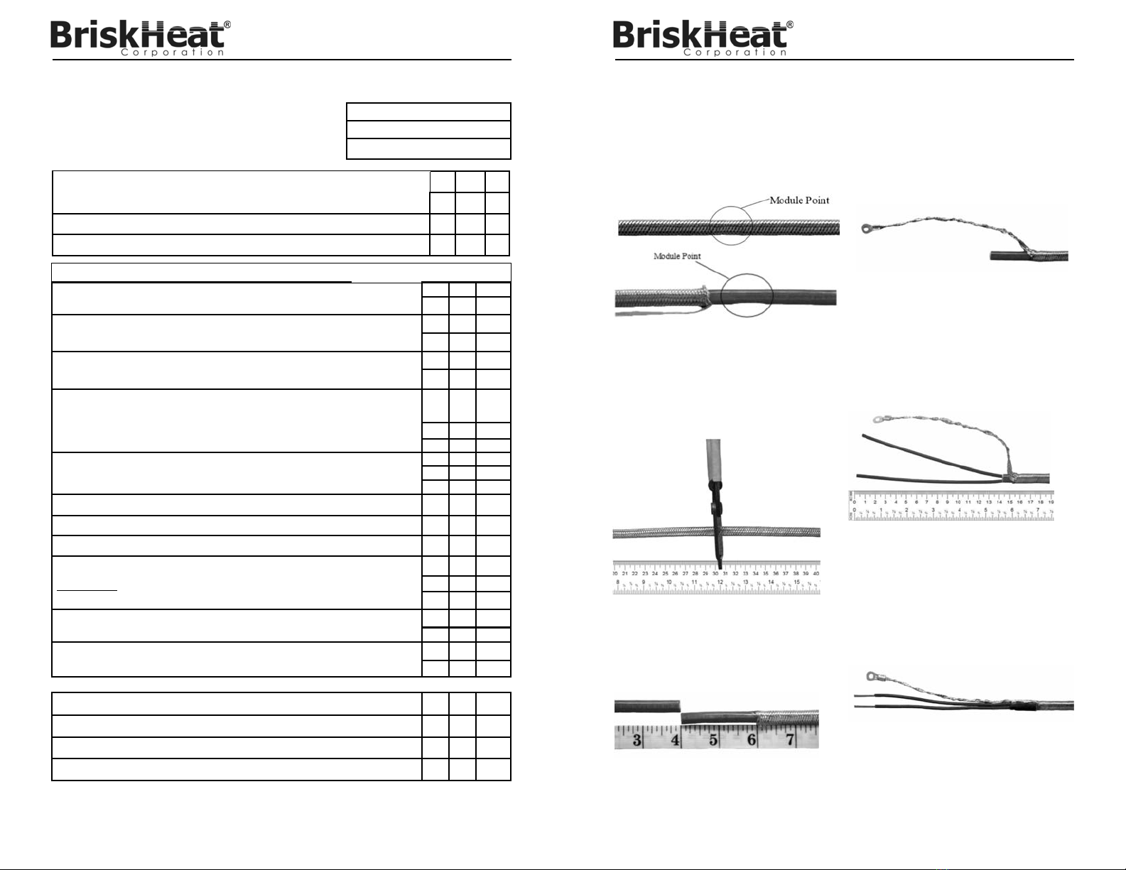
LEAD TERMINATION PREPARATION
STEP 3A:
Push 6 in (152 mm) of the metallic overbraid
back to expose the extruded jacket on the cable.
Using a pair of Wire Cutters, cut off 4 in (101
mm) of the exposed cable.
STEP 5:
Slide the metallic overbraid back at least an
additional 6 in (152 mm) to further expose the
cable jacket. Using a knife, carefully cut and
remove 6 in (152 mm) of the extruded jacket to
expose the spirally wrapped resistance wire and
the two bus wires. Do NOT damage the bus wires
or the bus wire insulation; the resistance wire must
NOT come into contact with the exposed bus
wires. Unwrap and cut the resistance wire back to
the point you cut the cable jacket.
STEP 6:
Slide a lead pouch over the two bus wires and
over the extruded jacket. Push the metallic braid
up to the lead pouch. Slide a shrink tube over the
lead pouch and the metallic braid. Using a heat
gun or other appropriate heating device, apply
heat evenly over the entire surface of the tube,
shrinking it over the metallic braid and lead pouch.
Using wire strippers, remove 0.75 in (19 mm) of
the insulation from the bus wires to expose the
conductors.
STEP 2:
Cut the cable between the module points for the
desired length of cold lead. The length of “cold
lead” must be at least 12 in (305 mm) but no longer
than the module length minus 6 in (152 mm). The
section of cable between the end of the cable and
the first module point will be the cold lead. This
section will be used for lead termination / power
input connection.
STEP 4:
Pull the metallic braid back over the end of the
cable. Push the cable through the side of the
metallic braid. Twist the empty braid to form a
pigtail lead and crimp a ring terminal on the end
(see picture above). A crimp barrel can also be
used to extend the ground (braid) to another 12
AWG ground wire.
STEP 1:
Determine the module length of the heating cable.
Module points can be identified by slight
indentations on the rounded surface of the outer
jacket. You can determine the module point by
touch or visually by sliding back the metallic
overbraid.

© BriskHeat Corporation. All rights reserved.
6
FE-Series Heating Cable Installation Instructions
END TERMINATION PREPARATION
STEP 1:
Locate the last module point of the cable run. Cut the cable 6 in (152 mm) beyond this point to form a
cold end.
STEP 2:
Using diagonal cutters and / or a knife, remove 0.75 in (19 mm) of the metallic braid and 0.50 in (12 mm)
of the extruded jacket to expose the inner wrap. Remove the inner wrap back to the extruded jacket to
expose the spirally wrapped resistance wire and the two insulated bus wires. Unwrap and cut off the
resistance wire back to the inner wrap. Be careful not to damage the insulation on the bus wires. Cut one
of the bus wires 0.25 in (6 mm) shorter than the other one. Make certain the resistance wire, the two bus
wires, and the metallic braid do NOT contact each other.
STEP 3:
Slide an end pouch over the two bus wires and extruded jacket. Slide a shrink tube over the end pouch
and the metallic overbraid. Using a heat gun or other appropriate heating device, apply heat evenly over
the entire surface of the tube, shrinking it over the metallic braid and end pouch.
NOTE: When attaching the heating cable to the pipe, make sure that the last module point is in
contact with the pipe surface.
Module Point
© BriskHeat® Corporation. Tutti i diritti riservati.
71
Cavo scaldante Serie FE Istruzioni di installazione
TEST DI RESISTENZA ALL'ISOLAMENTO ELETTRICO
Dei test elettrici sono raccomandati in punti specifici durante la ricezione e l'installazione del cavo
scaldante. Questo test periodico è progettato per impedire il dispendio di manodopera sprecata in caso
di danni al prodotto. I costi di installazione del cavo e l'isolamento termico sono molto maggiori rispetto al
costo del cavo scaldante. L'identificazione rapida di eventuali danni al cavo scaldante è l'approccio più
economico di un'installazione. Si raccomanda un test di resistenza di isolamento al seguente punto del
processo di installazione:
UPON RECEIPT of the heating cable
BEFORE thermal INSULATION installation
IMMEDIATELY AFTER thermal insulation installation
As part of a PERIODIC MAINTENANCE program
Procedura
Il test di resistenza di isolamento viene utilizzato per verificare la presenza di danni alle guaine estruse.
Le connessioni per il test megger sono realizzate come mostrato.
Nota: Il test dovrebbe utilizzare almeno 500 V C.C. Non utilizzare un test megger con oltre 2500 V
C.C. Le letture minime accettabili dovrebbero essere di 20 megaohm per circuito,
indipendentemente dalla lunghezza.
Una registrazione dovrebbe essere tenuta dai valori misurati dal momento in cui il cavo viene installato
la prima volta sul tubo. Una cronologia della lettura della resistenza d'isolamento può essere utile per
individuare infiltrazioni di umidità nel sistema elettrico (osservando un graduale declino della resistenza
di isolamento o danni fisici al cavo scaldante (forte calo della resistenza di isolamento). Viene mostrato
un record di esempio per questo. (Vedere la sezione Modulo di controllo dell'ispezione periodica di
questo manuale).
500 VDC
MEGGER
500 VDC
MEGGER
REGISTRAZIONE PERIODICA DI ISPEZIONE
Il modulo per la registrazione delle ispezioni periodiche può essere utilizzato in due modi :
1. Un foglio per circuito - I risultati dei test periodici di un unico circuito sono immessi in colonne
verticali, a partire da sinistra e compilando verso destra. Questo permette un facile confronto dei
valori di prova fino a sette sequenze di test su un singolo circuito.
2. Un circuito per colonna - I dati dei test per una singola sequenza di test su ben sette circuiti
possono essere registrati su un singolo foglio.
Per ulteriori moduli di registrazione periodica di ispezione, contattare il proprio distributore /
rappresentante locale o Briskheat al numero 1-800-848-7673 (numero verde, Stati Uniti / Canada) o
1-674-294-3376 (mondiale) o bhtsale[email protected].
PER I CAVI SCALDANTI CON GUAINA
Testare dai fili del bus del cavo scaldante alla
guaina.
PER I CAVI SCALDANTI CON GUAINA E CONTENITORE
ESTERNO
Test A - (linee continue) dai fili del bus del cavo scaldante alla
guaina.
Test B - (linee tratteggiate) dalla guaina al tubo di metallo.

© BriskHeat® Corporation. Tutti i diritti riservati.
70
Cavo scaldante Serie FE Istruzioni di installazione
POSIZIONAMENTO DEL CAVO SCALDANTE SUI DIVERSI TIPI DI
OGGETTI
INSTALLARE L'ISOLAMENTO TERMICO
È vivamente raccomandato di utilizzare l'isolamento termico con questo prodotto. Per assistenza sull'applica-
zione e sui consigli di isolamento, contattare il proprio rappresentante locale BriskHeat o direttamente noi per
eseguire un'analisi termica dell'applicazione.
Per le applicazioni che richiedono la conformità FM o CE, è richiesto un isolamento termico e uno spessore
non superiore a 25,4 mm. Per applicazioni che richiedono un isolamento di spessore superiore a 25,4 mm,
contattare il rappresentante locale BriskHeat o rivolgersi direttamente a noi per eseguire un'analisi termica
dell'applicazione e per verificare la conformità FM e/o CE.
Dopo l'installazione dell'isolamento termico, si consiglia un test di resistenza all'isolamento prima di alimentare
il sistema. Vedere la sezione TEST DI RESISTENZA ALL'ISOLAMENTO ELETTRICO di queste istruzioni per
informazioni circa la procedura del test di resistenza all'isolamento.
Supporto del tubo
Raccordo a gomito
Corpo flangia
Valvola
Raccordo a T cieco
Supporto
Posizione
consigliata del
sensore di
temperatura
© BriskHeat Corporation. All rights reserved.
7
FE-Series Heating Cable Installation Instructions
POWER INPUT CONNECTION INSTALLATION
STEP 2:
Place the standoff on the pipe surface at the
point where the supply wiring and associated
fittings will connect to the pipe heat tracing
cable. Fasten the standoff to the pipe with pipe
straps. Fill the top of the standoff with Silicone
RTV to provide a moisture seal between the
pipe and electrical junction box. Make certain
there are no voids between the cable and pipe
standoff. Allow an appropriate amount of time
for the Silicone RTV to cure.
STEP 1:
Prepare heating cable end as specified under
“Lead Termination Preparation”. Insert
approximately 8 in (200 mm) of the heating cable
(s) through the bottom of the cast aluminum pipe
standoff, making sure the first module point stays
in contact with the pipe.
NOTE: A maximum of three cables fit through
pipe standoff.
STEP 3:
Ensure the junction box chosen is equipped with a minimum of two 1
in NPT female threaded hubs. Secure junction box onto the standoff.
Pull the input power source wiring through the associated opening
into the junction box. Connect the heating cable lead wires to a
temperature controlling device and input power source wiring using
wire nuts provided. Be sure to follow temperature controlling device
installation instructions. If applicable, secure the braided pigtail
ground to the standoff using the standoff ground screw provided or to
the junction box using the junction box ground screw/receptacle.
Ensure an adequate earth ground is provided to safely ground the
entire assembly. Close the junction box and attach the Caution
Label to the cover of the junction box.
Only authorized and trained personnel should perform the following procedure. The hazard of
electrical shock exists with any electrical installation project. Disconnect all supply power at the
source prior to making the heating cable power input connections.
A temperature controller is required for all constant-wattage heating cable.
CAUTION

© BriskHeat Corporation. All rights reserved.
8
FE-Series Heating Cable Installation Instructions
STEP 1:
Prepare the heating cable ends to be spliced together as specified under “Lead Termination
Preparation”.
CAUTION: Never connect the two parallel conductors of the heating cable together.
STEP 2:
Insert the heating cable cold leads up through the pipe standoff and into the junction box. Attach the
pipe standoff and junction box to the pipe where the splice is to be located. Fasten it with appropriately
sized pipe clamps.
NOTE: A maximum of three cables fit through pipe standoff.
STEP 3:
Connect the leads of the heating cable ends together using wire nuts as shown in the illustrations (wire
nuts are not provided with FECABSK).
Tee Splice In-line Splice
STEP 4:
Connect the terminal lugs on the braid leads to a grounded screw on the pipe standoff or on the junction
box.
NOTE: The junction box and pipe standoff must be grounded.
STEP 5:
Test the cable installation for continuity and insulation resistance. The insulation resistance between
the bus wires and the metallic braid must be greater than 50 megohms at 500 volts. Close the
junction box and attach the Caution Label to the cover of the junction box.
SPLICE INSTALLATION
Only authorized and trained personnel should perform the following procedure. The hazard of
electrical shock exists with any electrical installation project. Disconnect all supply power at the source
prior to making the heating cable power input connections.
WARNING
© BriskHeat® Corporation. Tutti i diritti riservati.
69
Cavo scaldante Serie FE Istruzioni di installazione
INSTALLAZIONE DEL CAVO SCALDANTE
Tecniche di confezionamento cavi
ATTENZIONE
Temperatura di installazione minima: -22°F (-30°C)
Il percorso rettilineo è il metodo più semplice per l'installazione del cavo scaldante. Su un singolo
oggetto, è possibile avere più percorsi rettilinei. Con un singolo percorso rettilineo, posizionare il cavo
sul fondo di un tubo orizzontale.
Non avvolgere il cavo scaldante su se stesso e accertarsi che due
cavi scaldanti non si tocchino .
Tutte le parti del cavo scaldante devono essere a contatto con la superficie
da riscaldare. Usare stucco conduttivo termico per riempire i vuoti tra il cavo e la superficie del tubo.
Avvolgere il nastro adesivo ogni 12" (305 mm) attorno al cavo scaldante e il tubo per collegare il cavo.
La resistenza di isolamento minima accettabile dopo l'installazione e l'isolamento termico del sistema: La
misurazione è stata effettuata applicando 500 V cc tra ciascun circuito e terra con il set diseccitato e tutti
i neutri del circuito isolati da terra.
L'avvolgimento a spirale offre una maggiore copertura del riscaldatore rispetto ad un percorso rettilineo.
Questo metodo potrebbe anche richiedere più cavo scaldante. Prima dell'installazione, verificare la
lunghezza del passo (vedi figura) per assicurarsi di avere cavo scaldante sufficiente per finire il lavoro.
Se si ha bisogno di assistenza nella determinazione della lunghezza del passo, contattare il distributore
locale o BriskHeat®.
Non avvolgere il cavo scaldante su se stesso e accertarsi che due cavi
scaldanti non si tocchino.
Il raggio di curvatura minimo non può superare 254 mm.
Tutte le parti del cavo scaldante devono essere a contatto con la superficie da riscaldare. Usare stucco
conduttivo termico per riempire i vuoti tra il cavo e la superficie del tubo.
Avvolgere il nastro adesivo ogni 12" (305 mm) attorno al cavo scaldante e il tubo per collegare il cavo.
Dopo l'installazione del cavo scaldante, si raccomanda di eseguire un test di resistenza all'isolamento prima
dell'installazione di qualsiasi isolamento termico. Vedere la sezione TEST DI RESISTENZA ALL'ISOLAMENTO
ELETTRICO di queste istruzioni per informazioni circa la procedura del test di resistenza all'isolamento.
305 mm
Nastro in fibra di vetro
Tratto rettilineo (vista laterale)
Cavo scaldante
Tratto rettilineo (vista dell'estremità)
Passo
Avvolgimento a spirale

© BriskHeat® Corporation. Tutti i diritti riservati.
68
Cavo scaldante Serie FE Istruzioni di installazione
INSTALLAZIONE DEL GIUNZIONE
FASE 1:
Preparare le estremità del cavo scaldante per essere collegate tra di loco, come specificato nella
sezione "Preparazione della terminazione del conduttore".
ATTENZIONE: Non collegare insieme i due conduttori paralleli del cavo scaldante.
FASE 2:
Inserire i conduttori freddi del cavo scaldante attraverso la colonnetta e nella scatola di derivazione.
Fissare la colonnetta e la scatola di giunzione al tubo lì dove la giunzione deve essere collocata. Fissare
con fascette di dimensioni appropriate.
NOTA: Un massimo di tre cavi possono essere passati attraverso la colonnetta.
FASE 3:
Collegare insieme le estremità dei conduttori del cavo scaldante con cappucci di protezione, come
mostrato nelle illustrazioni (i cappucci di protezione non sono dotati di FECABSK).
Giunzione a T Giunzione in linea
FASE 4:
Collegare le linguette di collegamento sui conduttori ad una vite di messa a terra sulla colonnetta o sulla
scatola di giunzione.
NOTA: La scatola di giunzione e la colonnetta devono essere messi a terra.
FASE 5:
Verificare la continuità dell'installazione del cavo per la e la resistenza di isolamento. La resistenza di
isolamento tra i fili bus e la treccia metallica deve essere superiore a 50 megaohm a 500 volt. Chiudere
la scatola di giunzione e applicare l'etichetta Attenzione al coperchio della scatola di giunzione.
AVVERTIMENTO
Solo il personale autorizzato e qualificato deve eseguire la seguente procedura. Durante qualsiasi
progetto di installazione elettrica esiste il pericolo di scosse elettriche. Scollegare tutte le fonti di
alimentazione elettrica prima di effettuare le connessioni di ingresso dell'alimentazione del cavo
scaldante .
© BriskHeat Corporation. All rights reserved.
9
FE-Series Heating Cable Installation Instructions
HEATING CABLE INSTALLATION
Spiral wrapping provides more heater coverage than a straight run. It can also require more heating
cable. Verify the pitch length (see illustration) prior to installation to ensure you have enough heating
cable to finish the job. If you need assistance in determining the pitch length, call your local distributor or
BriskHeat.
Do not wrap the heating cable over itself or have two heating cables
touch.
Minimum bend radius may not exceed 1 in (25.4 mm).
All parts of heating cable must make intimate contact with surface to be heated. Use heat conductive
putty to fill voids between cable and pipe surface.
Wrap adhesive tape every 12 in (305 mm) around heating cable and pipe to attach the cable.
After heating cable installation, an insulation resistance test is recommended before installation of any
thermal insulation. See ELECTRICAL INSULATION RESISTANCE TEST section of these instructions
for insulation resistance test procedure.
Minimum installation temperature: -22°F (-30°C)
Cable Wrapping Techniques
A straight run is the simplest method to installing heating cable. It is possible to have multiple straight
runs on a single object. With a single straight run, position cable at the bottom of a horizontal pipe.
Do not wrap the heating cable over itself or have two heating cables
touch.
All parts of heating cable must make intimate contact with surface to be heated. Use heat conductive
putty to fill voids between cable and pipe surface.
Wrap adhesive tape every 12 in (305 mm) around heating cable and pipe to attach the cable.
Spiral wrap
12 in (305 mm)
Fiberglass Tape
Straight Run (side view)
Heating Cable
Straight Run (end view)
Pitch

© BriskHeat Corporation. All rights reserved.
10
FE-Series Heating Cable Installation Instructions
Heating Cable Placement on Different Types of Objects
Valve
Support
Recommended
Temp Sensor
Location
Blind Tee
Elbow
Flange
INSTALLING THERMAL INSULATION
It is highly recommended that thermal insulation is used with this product. For application assistance
and an insulation recommendation, please contact your local BriskHeat representative or us directly to
perform a thermal analysis for your application.
For applications requiring FM or CE compliance, thermal insulation is required and not to exceed 1 in
(25.4 mm) thick. For applications requiring greater than 1 in (25.4 mm) insulation, contact your local
BriskHeat representative or us directly to perform a thermal analysis for your application and to verify
FM and/or CE compliance.
After the installation of thermal insulation, an insulation resistance test is recommended before ener-
gizing the system. See ELECTRICAL INSULATION RESISTANCE section of these instructions for
insulation resistance test procedure.
Pipe Support
© BriskHeat® Corporation. Tutti i diritti riservati.
67
Cavo scaldante Serie FE Istruzioni di installazione
INSTALLAZIONE COLLEGAMENTO DELL’INGRESSO DI
ALIMENTAZIONE
AVVERTIMENTO
Solo il personale autorizzato e qualificato deve eseguire la seguente procedura. Durante qualsiasi
progetto di installazione elettrica esiste il pericolo di scosse elettriche. Scollegare tutte le fonti di
alimentazione elettrica prima di effettuare le connessioni di ingresso dell'alimentazione del cavo
scaldante.
FASE 1:
Preparare l'estremità del cavo scaldante come
specificato nella sezione "Preparazione della
terminazione del conduttore". Inserire circa 200
mm del cavo scaldante/dei cavo scaldanti
attraverso ila parte inferiore della colonnetta in
alluminio, assicurandosi che il primo punto
modulare rimanga in contatto con il tubo.
NOTA: Un massimo di tre cavi possono essere passati
attraverso la colonnetta.
FASE 3:
Assicurarsi che la scatola di giunzione scelta sia
dotata di almeno due mozzi filettati femmina da 1 pollice NPT.
Fissare la scatola di giunzione sul distanziatore. Tirare il
cablaggio della fonte di alimentazione in ingresso attraverso
l'apertura associata nella scatola di giunzione. Collegare i fili del
cavo di riscaldamento ad un dispositivo di controllo della
temperatura e inserire il cablaggio della fonte di alimentazione
utilizzando i dadi forniti. Assicurarsi di seguire le istruzioni di
installazione del dispositivo di controllo della temperatura. Se
applicabile, fissare la terra del codino intrecciata al distanziatore
usando la vite di messa a terra del distanziatore in dotazione o
alla scatola di giunzione usando la vite di messa a terra della
scatola di giunzione / presa. Assicurarsi che sia presente
un'adeguata messa a terra per mettere a terra in sicurezza l'intero
assieme.Chiudere la scatola di giunzione e applicare l'etichetta
Attenzione al coperchio della scatola di giunzione.
ATTENZIONE
Per tutti i cavi scaldanti a potenza constante è necessario un regolatore di temperatura.
FASE 2:
Posizionare la superficie della colonnetta nel punto
in cui il cablaggio di alimentazione ed i relativi
accessori si collegheranno al cavo di
instradamento del calore per il tubo. Fissare la
colonnetta al tubo con fascette di fissaggio.
Riempire la parte superiore della colonnetta con
silicone RTV per fornire una tenuta di umidità tra il
tubo e la scatola di giunzione elettrica. Assicurarsi
che non ci siano spazi vuoti tra il cavo e la
colonnetta. Lasciare un tempo sufficiente per la
solidificazione del silicone RTV.

© BriskHeat® Corporation. Tutti i diritti riservati.
66
Cavo scaldante Serie FE Istruzioni di installazione
PREPARAZIONE TERMINAZIONE FINALE
FASE 1:
Individuare l'ultimo punto modulare nel tratto del cavo. Tagliare 152 mm del cavo oltre questo punto in
modo da formare un'estremità fredda.
FASE 2:
Utilizzando una taglierina diagonale e/o con un coltello, rimuovere 19 mm della treccia metallica e
0,50" (1,2 cm) del rivestimento estruso per esporre l'involucro interno. Rimuovere l'involucro interno fino
al rivestimento estruso per esporre il filo resistivo avvolto a spirale ed i due fili bus isolati. Sfasciare e
tagliare di nuovo il filo resistivo fino all'involucro interno. Fare attenzione a non danneggiare l'isolamento
sui fili bus. Tagliare uno dei fili bus con 6 mm più corto rispetto all'altro. Accertarsi che il filo resistivo, i
due fili bus e la treccia metallica NON siano a contatto tra di loro.
Punto modulare
FASE 3:
Infilare un copriconduttore sui due fili bus e sul rivestimento estruso. Infilare un tubo retraibile sul
copriconduttore e sulla calza metallica. Utilizzando una pistola termica o altro dispositivo di riscaldamen-
to adeguato, riscaldare in modo uniforme tutta la superficie del tubo, restringendolo sopra la treccia
metallica e il copriconduttore.
NOTA: Quando si collega il cavo scaldante al tubo, assicurarsi che l'ultimo punto modulare è a contatto
con la superficie del tubo.
© BriskHeat Corporation. All rights reserved.
11
FE-Series Heating Cable Installation Instructions
Note: Test should use at least a 500 VDC megger. Do not use a megger with an excess of 2500 VDC.
Minimum acceptable readings should be 20 megaohms per circuit, regardless of length.
FOR HEATING CABLES WITH BRAID
Test from heating cable bus wires to braid.
FOR HEATING CABLES WITH BRAID AND OUTER
JACKET
Test A - (solid lines) from heating cable bus wires to
braid.
Test B - (dotted lines) from braid to metal pipe.
A record should be kept of the readings taken from the time the cable is first installed on the pipe. A
history of the insulation resistance reading can be helpful in spotting moisture ingress into the electrical
system (indicated by a gradual decline in the insulation resistance) or physical damage to the heating
cable (indicated by a sharp decline in the insulation resistance). A sample record for this is shown. (See
Periodic Inspection Record Form section of this manual).
ELECTRICAL INSULATION RESISTANCE TEST
Electrical tests are recommended at specific points in the receipt and installation of the heating cable.
This periodical testing is designed to prevent the expenditure of wasted labor in the event of damage to
the product. Installation costs of the cable and thermal insulation are much greater than the heating
cable. Quick identification of any heating cable damage is the most economic approach to an installa-
tion. An insulation resistance test is recommended at the following point of the installation process:
UPON RECEIPT of the heating cable
BEFORE thermal INSULATION installation
IMMEDIATELY AFTER thermal insulation installation
As part of a PERIODIC MAINTENANCE program
Procedure
The insulation resistance test is used to check for damage to extruded jackets. Connections for the
megger are made as shown.
500 VDC
MEGGER
500 VDC
MEGGER
PERIODIC INSPECTION RECORD
The Periodic Inspection record Form may be used in one of two ways:
1. One sheet per circuit - The results of periodic tests of a single circuit are posted in vertical
columns, beginning on the left and working toward the right. This allows easy comparison of test
values for up to three test sequences on an individual circuit.
2. One circuit per column - Test data for a single test sequence on as many as three circuits can
be recorded on a single sheet.
For additional Periodic Inspection Record Forms, contact your local distributor/representative or
Briskheat at 1-800-848-7673 (toll free, U.S. / Canada) or 1-674-294-3376 (Worldwide) or

© BriskHeat Corporation. All rights reserved.
12
FE-Series Heating Cable Installation Instructions
Maintenance Checks for _____________ Month _____________Year_________________
Visual inspection inside connection box Initial
corrosion, moisture, etc. Date
Damage or cracks (leaks) in insulation Initial
seals at valves, hangers, pumps, etc. Date
Heating cable properly connected and Initial
grounded. heating cable and connections
insulated from connection box. Date
Thermostat checked for moisture, corrosion, Set Point
set point, switch operation, and capillary Initial
damage Date
Megger tests performed at power Reading
connection with both bus wires disconnected Initial
from power wiring. Date
Circuit voltage at power connection. Reading
Circuit amperage after 5 minutes Reading
Pipe temperature at time amps were measured. Reading
Watts/Ft.
Volts x Amps = w/ft. Initial
feet Date
All connections, boxes, and thermostats Initial
have been resealed. Date
End seals, covered splices and tees marked Initial
On insulation cladding. Date
Remarks & Comments
Circuit Number
Heater Type
Circuit Length
Periodic Inspection Record Form
Freeze Protection Circuits -
Perform these checks as season requiring use approaches.
Temperature Maintenance Circuits -
Perform these checks at least twice per year.
© BriskHeat® Corporation. Tutti i diritti riservati.
65
Cavo scaldante Serie FE Istruzioni di installazione
PREPARAZIONE TERMINAZIONE
FASE 5:
Far scorrere la calza metallica indietro almeno altri
152 mm per esporre ulteriormente il rivestimento
del cavo. Con un coltello, tagliare con cura e
rimuovere 152 mm del rivestimento estruso per
esporre il filo resistivo avvolto a spirale ed i due fili
bus. NON danneggiare i fili bus o l'isolamento del
filo bus; il filo resistivo NON deve venire a contatto
con i fili del bus esposti. Sfasciare e tagliare il filo
resistivo di nuovo al punto dove avete tagliato il
rivestimento del cavo.
FASE 6:
Infilare un copriconduttore sui due fili bus e sul
rivestimento estruso. Spingere la treccia metallica
fino al copriconduttore. Infilare un tubo retraibile
sul copriconduttore e sulla treccia metallica.
Utilizzando una pistola termica o altro dispositivo
di riscaldamento adeguato, riscaldare in modo
uniforme tutta la superficie del tubo, restringendolo
sopra la treccia metallica e il copriconduttore.
Utilizzando spellafili, rimuovere 19 mm di
isolamento dai fili bus per esporre i conduttori.
FASE 2:
Tagliare il cavo tra i punti modulari alla lunghezza
desiderata del conduttore freddo. La lunghezza di
"conduttore freddo" deve essere almeno 305 mm,
ma non superiore alla lunghezza del modulo meno
152 mm. La sezione del cavo tra l'estremità del
cavo e il primo punto modulare sarà il conduttore
freddo. Questa sezione sarà utilizzata per la
terminazione del conduttore/connessione di
ingresso potenza.
FASE 4:
Tirare la treccia posteriore metallica nuovamente
sull'estremità del cavo. Inserire il cavo attraverso il
lato della treccia metallica. Torcere la treccia vuota
in modo da formare una treccina e fissare un
terminale ad anello sull'estremità (vedi foto sopra).
Può essere usato anche un cilindro di crimpatura
per estendere la messa terra (treccia) ad un altro
filo di messa a terra 12AWG.
FASE 1:
Determinare la lunghezza di modulo del cavo
scaldante. I punti modulari possono essere
identificati da lievi rientranze sulla superficie
arrotondata della guaina esterna. È possibile
determinare il punto modulare con il tatto o
visivamente facendo scorrere indietro la calza
metallica.
Punto modulare
Punto modulare
FASE 3A:
Spingere indietro 152 mm della calza metallica per
esporre il rivestimento estruso sul cavo.
Utilizzando un tronchese, tagliare 101 mm del
cavo esposto.
MM CM INCH

© BriskHeat® Corporation. Tutti i diritti riservati.
64
Cavo scaldante Serie FE Istruzioni di installazione
FECABUC:
Collegamento universale/kit di terminazione.
3-copriconduttori
2-cappucci terminali
6-tubi retraibili
1-sigillante RTV tubetto da 3 oz.
1-etichetta Attenzione
2-terminali ad anello
Connettori 2-Splice 12-10 AWG
3-Cappucci di protezione
1 Colonnetta NPT da 1 pollice
2 -fascette per tubi
Abbastanza per completare una connessione di
ingresso di alimentazione o una giunzione di
alimentazione, tre terminazioni di derivazione e
due terminazioni di estremità.
NOTA: Richiede una scatola di giunzione a doppio
mozzo.
FECABKC:
Kit di collegamento/terminazione
5-copriconduttori
5-copriconduttori
10-tubi retraibili
Abbastanza per completare cinque terminazioni di
piombo e cinque terminazioni di estremità.
PRIMA DELL'INSTALLAZIONE
FASE 1:
Controllare eventuali danni al riscaldatore come strappi, perforazioni, ecc. Verificare che la superficie da
riscaldare sia priva di bordi frastagliati o taglienti o schizzi di saldatura.
FASE 2:
Accertarsi che tutto l'hardware e gli utensili di installazione necessari siano facilmente disponibili. A
seconda dell'applicazione, ciò può comprendere:
Utensili
Attrezzi ed accessori
FASE 3:
(A) Accertarsi che l'amperaggio totale del sistema non superi l'amperaggio massimo che può essere
sopportato dai componenti del sistema di riscaldamento. (B) Verificare che la lunghezza totale
necessaria del cavo non superi la lunghezza massima del circuito. Se la lunghezza del cavo supera (A)
o (B), il cavo deve essere suddiviso in sezioni.
FECABSK:
Kit di giunzione.
3-copriconduttori
1-copriconduttore
3-tubi retraibili
1-sigillante RTV tubetto da 3 oz.
1-etichetta Attenzione
3-terminali ad anello
Connettori 2-Splice 12-10 AWG
Abbastanza per completare una giunzione in linea o
una giunzione a T, tre terminazioni di derivazione e
una terminazione di estremità.
NOTA: Richiede scatola di giunzione a mozzo
singolo, distanziatore tubi, due cinghie per tubi.
FECABLP:
Kit terminazione filo.
1-copriconduttore
1-tubo retribile
Sufficiente per completare terminale con
un'estremità.
FECABEP:
Kit terminazione finale
1-copriconduttore
1-tubo estraibile
Sufficiente per completare terminale con
un'estremità.
Taglierino diagonale Pistola termica Coltello
Strumento di piegatura/spellafili Nastro/righello di misurazione Cacciavite
Regolatore di temperature
Sensore di temperatura
Kit di collegamento/terminali
(vedi descrizioni kit per
verificare contenuti ed altri
attrezzi necessari)
Materiale isolante
Kit illuminazione monitor
(opzionale)
Sigillante RTV
Fascette per tubi
Scatola di giunzione 1 pollice
NPT
Cappucci di protezione
Etichette Attenzione
Nastro adesivo in alluminio o
fibra di vetro (verificare la
temperatura nominale)
Stucco conduttivo termico
Riduttore di tubo 1 pollice
NPT
DESCRIZIONI KIT DI COLLEGAMENTO/TERMINAZIONE
© BriskHeat Corporation. All rights reserved.
13
FE-Series Heating Cable Installation Instructions
Maintenance:
All maintenance should be performed after the heater has cooled to room temperature and with
the electricity disconnected.
Dirt, oil, grease or other foreign matter can be removed with a damp rag and mild household
cleaners.
Do not attempt to repair a damaged heater.
Storage:
This product should be stored at room temperature in an environment with less than 80% relative
humidity.
Disposal:
This product does not contain any hazardous substances and may be discarded with domestic
waste.
Anyone who reads and understands these
instructions is qualified to maintain this heater.
MAINTENANCE INSTRUCTIONS
EMERGENCY PROCEDURES
Read and understand these procedures prior to using this heater.
Disconnect power to the heater in the event of an emergency.
Electric Shock:
Do not touch the injured person while they are still in contact with the electrical current.
Call your local emergency service if the injured person experiences: severe burns, confusion,
difficulty breathing, heart rhythm problems, cardiac arrest, muscle pain and contractions, seizures
or a loss of consciousness.
Minor Burns:
Hold the burned area under cool running water for 10-15 minutes.
Remove rings or other tight items from burned area.
Major Burns:
Call your local emergency service.
Protect the person from further harm.
Remove rings or other tight items from burned area.
Monitor breathing and perform CPR if necessary.
Fire:
Call your local emergency service.

© BriskHeat Corporation. All rights reserved.
14
FE-Series Heating Cable Installation Instructions
TROUBLESHOOTING GUIDE
Please read this guide prior to contacting BriskHeat. This guide is designed to answer the most
commonly asked questions. If you are unable to identify the problem or need additional assistance,
please contact your local distributor/ representative or us at 1-800-848-7673, 614-294-3376, or
Cable 120 VAC
ft (m)
208 VAC
ft (m)
240 VAC
ft (m)
277 VAC
ft (m)
480 VAC
ft (m)
3 W/ ft (10 W/m) 640 (195) 1110 (338) 1280 (390) N/A 2560 (780)
385 (117) 665 (203) 770 (234) N/A 1535 (468)
8 W/ ft (26 W/m) 240 (73) 415 (127) 480 (146) 555 (169) 960 (293)
12 W/ ft (39 W/m) 160 (49) 277 (85) 320 (98) 370 (113) 640 (195)
Maximum Circuit Length
PROBLEM SOLUTION(S)
Entire heating cable run does not heat Verify heater is connected to proper voltage.
Check to see if there is a resistance reading (not an
open circuit) in heater using an ohm meter.
Portion of heating cable does not heat Examine unheated module for damage.
Circuit breaker is tripping Validate that the circuit breaker is capable of handling
the amp requirement of heater.
Examine heater and power wiring for any damage.
Verify open circuit exists between bus wire and ground
braid.
Ensure heater length does not exceed maximum circuit
length (See table below).
© BriskHeat® Corporation. Tutti i diritti riservati.
63
Cavo scaldante Serie FE Istruzioni di installazione
IMPORTANTI ISTRUZIONI DI SICUREZZA
SIMBOLO DI PERICOLO
Il simbolo di cui sopra è utilizzato per richiamare la vostra attenzione alle istruzioni per la sicurezza personale. Tale
simbolo rileva importanti precauzioni di sicurezza. Significa "ATTENZIONE! Sia attento! La sicurezza personale è
coinvolta! " Leggere il messaggio che segue e fare attenzione alla possibilità di lesioni personali o di morte.
L'utente finale deve rispettare le seguenti:
Solo il personale qualificato è autorizzato a
collegare i cavi elettrici.
Prima di effettuare i collegamenti elettrici,
scollegare tutti i cavi di alimentazione dalla fonte
elettrica.
Tutti i collegamenti elettrici devono seguire le
norme elettriche locali e le raccomandazioni
secondo l'art. 427 del NEC.
La persona che esegue l'installazione / IL
cablaggio finale deve essere qualificata per
questo lavoro.
L'utente finale è responsabile di fornire un
dispositivo di sezionamento adatto.
L'utente finale è responsabile di fornire un
dispositivo di protezione elettrica adeguato. Si
consiglia vivamente di usare un interruttore guasto
a terra.
La mancata osservanza di queste avvertenze può
provocare lesioni personali o danni al riscaldatore.
AVVERTIMENTO
Non immergere il riscaldatore in liquidi.
Il riscaldatore deve essere mantenuto a 13 mm
lontano da qualsiasi materiale combustibile.
Utilizzare il riscaldatore solamente nelle aree
omologate.
Mantenere gli oggetti affilati in metallo lontano dal
riscaldatore.
Il mancato rispetto delle presenti avvertenze potrebbe
comportare scosse elettriche, rischio di incendi e lesioni
personali.
PERICOLO
Una persona che non ha letto e compreso tutte le istruzioni
per l'uso non è qualificata per utilizzare questo prodotto.
PERICOLO
Non maneggiare mai il riscaldatore durante il suo
funzionamento, scollegare sempre il riscaldatore
dalla fonte di alimentazione e farlo raffreddare
prima di maneggiarlo.
Ispezionare il riscaldatore e i kit di collegamento
prima dell'utilizzo.
Non utilizzare mai il riscaldatore senza un
dispositivo di controllo della temperatura.
Non avvolgere il cavo scaldante su se stesso.
Se si verifica una fuoriuscita di corpi estranei sul
riscaldatore, scollegare dalla fonte di alimentazione
pulita dopo aver lasciato raffreddare il riscaldatore.
Non utilizzare mai un riscaldatore senza una dissipa-
tore di calore appropriato (il dispositivo che viene
riscaldato è considerato un dissipatore di calore).
Non utilizzare il riscaldatore oltre il valore di tem-
peratura nominale.
Fissare il riscaldatore al dispositivo utilizzando
solamente i metodi certificati.
Non riparare riscaldatori danneggiati o difettosi.
Non schiacciare o applicare forti sollecitazioni
fisiche sul gruppo del riscaldatore o del cavo.
Scollegare il riscaldatore quando non in uso.
La mancata osservanza delle presenti avvertenze potrebbe
comportare lesioni personali o danni al riscaldatore.
ATTENZIONE
Pericoli immediati che POSSONO provocare gravi lesioni
personali o morte
Pericoli o pratiche non sicure che POTREBBERO
provocare gravi lesioni personali o morte
Pericoli o pratiche non sicure che POTREBBERO
provocare lesioni personali lievi o danni alla proprietà
PERICOLO
AVVERTENZA
ATTENZIONE

© BriskHeat® Corporation. Tutti i diritti riservati.
62
Cavo scaldante Serie FE Istruzioni di installazione
SOMMARIO
Introduzione ......................................................................................................................................... 62
Applicazioni ........................................................................................................................................... 62
Approvazione ........................................................................................................................................ 62
Impotani istruzioni di sicurezza ............................................................................................................. 63
Descrizioni kit di collegamento/terminazione ........................................................................................ 64
Prima dell'installazione ......................................................................................................................... 64
Preparazione terminazione a piombo ................................................................................................... 65
Preparazione terminazione finale ......................................................................................................... 66
Installazione collegamento dell'ingresso di alimentazione .................................................................... 67
Installazione del giunzione .................................................................................................................... 68
Installazione del cavo scaldante ........................................................................................................... 69
Installare l'isolamento termico ............................................................................................................... 70
Test di resistenza all'isolamento elettrico .............................................................................................. 71
Registrazione periodica di ispezione ..................................................................................................... 71
Istruzioni di manutenzione ..................................................................................................................... 73
Procedure di emergenza ....................................................................................................................... 73
Guida alla risoluzione dei problemi ....................................................................................................... 74
Informazioni sulla garanzia ................................................................................................................... 75
INTRODUZIONE
Grazie per aver acquistato un sistema di cavi scaldanti a potenza elettrica costante serie FE BriskHeat.
Un sistema di cavi scaldante è una combinazione che include cavo scaldante, kit di collegamento/
terminazione, regolatore di temperatura e gli accessori in base all'applicazione specifica. Il riscaldatore è
progettato per fornire un servizio a lunga durata ed efficiente, tenendo in mente la funzionalità,
l'affidabilità e la sicurezza.
Tutti i cavi scaldanti a potenza elettrica costante BriskHeat utilizzano una progettazione modulare in
parallelo dei resistori. Questo design permette il taglio su misura del cavo scaldante e della
terminazione sul luogo di applicazione, senza influenzare la potenza termica per unità di lunghezza. Il
design modulare permette ai terminali dei cavi / collegamenti elettrici di essere realizzati con cavi freddi
e terminali freddi (ad esempio cavo non riscaldato in scatola di derivazione elettrica).
Per tutti i cavi scaldanti a potenza constante è necessario un regolatore di temperatura.
Per ulteriori informazioni su questo prodotto o altri prodotti BriskHeat , si prega di contattare il
distributore locale BriskHeat o di contattarci al numero verde (USA/Canada) 1-800-848-7673 o 614-294-
3376.
Applicazioni previste:
Riscaldamento per traccia generale
Riscaldamento di condutture / serbatoi / navi
Posizioni ordinarie e pericolose
Applicazione dell'area asciutta
Applicazioni vietate:
Uso esterno
Riscaldamento ad immersione
Utilizzare su dispositivi non metallici
Applicazione dell'area umida
APPLICAZIONI
Ordinary Locations
Hazardous Locations
Class I, Division 2, Groups B, C, & D
Class II, Division 2, Groups F & G
Class III, Division 2
Solo treccia di rame stagnato
Ordinary Locations
(120 and 230VAC only)
2014/35/UE (Direttiva bassa tensione)
IEC 60519-1:2015 60519-2:2006
2011/65 UE (direttiva RoHS 2)
2012/19/UE (WEEE direttiva)
Approvazioni validi solo se installato in conformità a tutte le istruzioni, i codici ed i regolamenti applicabili.
APPROVAZIONE
© BriskHeat Corporation. All rights reserved.
15
FE-Series Heating Cable Installation Instructions
WARRANTY INFORMATION
BriskHeat warrants to the original purchaser of this product for the period of eighteen (18) months from
date of shipment or twelve (12) months from date of installation, whichever comes first. BriskHeat’s
obligation and the exclusive remedy under this warranty shall be limited to the repair or replacement, at
BriskHeat’s option, of any parts of the product which may prove defective under prescribed use and
service following BriskHeat’s examination, is determined by BriskHeat to be defective. The complete
details of the warranty can be found online at www.briskheat.com or by contacting us at 1-800-848-7673
(toll free, U.S. / Canada) or 1-614-294-3376 (Worldwide).
Corporate Headquarters:
4800 Hilton Corporate Dr.
Columbus, OH 43232, U.S.A.
Toll Free: 800-848-7673
Phone: 614-294-3376
Fax: 614-294-3807
Email: [email protected]
Europe:
P.O. Box 420124
44275 Dortmund, Germany

16
Serie FE
Cable-Calefactor de Potencia
Constante
Manual de Instrucciones
Spanish (Español)
Debe leer y comprender este manual antes de instalar, hacer
funcionar o reparar este producto. La falta de comprensión de
estas instrucciones podría causar un accidente con lesiones
graves o la muerte.
Conserve estas instrucciones para futuras consultas.
61
Serie FE
Cavo Scaldante a Potenza
Elettrica-Costante
Manuale di Istruzioni
Italian (Italiano)
È necessario leggere e comprendere il presente manuale prima di
installare, utilizzare o eseguire interventi di manutenzione su
questo prodotto. La mancata comprensione di queste istruzioni
potrebbe causare un incidente con conseguenti lesioni gravi o
morte.
Conservare queste istruzioni per futura consultazione.

© BriskHeat® Corporation. Alle Rechte vorbehalten.
60
FE-Serie Heizkabel-Installationsanweisung
GARANTIEINFORMATION
BriskHeat gewährt dem ursprünglichen Käufer dieses Produkts Garantie für den Zeitraum von achtzehn
(18) Monaten ab Versanddatum oder zwölf (12) Monaten ab Installationsdatum, je nachdem, was zuerst
eintritt. Die Verpflichtung von BriskHeat und das ausschließliche Rechtsmittel gemäß dieser Garantie ist
nach Wahl von BriskHeat auf die Reparatur oder den Ersatz für jegliche Teile des Produkts beschränkt,
die sich unter vorgeschriebenen Verwendung und Wartung gemäß Prüfung durch BriskHeat als defekt
erweisen und nachdem die Mängel durch BriskHeat festgestellt wurden. Die vollständigen Einzelheiten
dieser Garantie erfahren Sie im Internet unter www.briskheat.com oder indem Sie uns kontaktieren unter
+1-800-848-7673 (gebührenfrei in U.S.A. und Kanada) oder unter +1-614-294-3376 (weltweit).
Firmensitz:
4800 Hilton Corporate Dr.
Columbus, OH 43232, USA.
Gebührenfrei: 800-848-7673
Telefon: 614-294-3376
Fax: 614-294-3807
E-Mail: [email protected]
Europa:
Postfach 420124
44275 Dortmund, Deutschland
© BriskHeat® Corporation. Todos los derechos reservados.
17
Instrucciones para instalación del cable calefactor
FE-Series
ÍNDICE
Introducción ......................................................................................................................................... 17
Aplicaciones .......................................................................................................................................... 17
Aprobaciones ........................................................................................................................................ 17
Instrucciones importantes de seguridad ............................................................................................... 18
Descripciones de los kits de conexión/terminación ............................................................................... 19
Antes de la instalación ......................................................................................................................... 19
Preparación de la conexión del conductor ............................................................................................ 20
Preparación de la conexión del extremo .............................................................................................. 21
Instalación de la conexión de entrada de alimentación ........................................................................ 22
Instalación del empalme de unión ........................................................................................................ 23
Instalación del cable calefactor ............................................................................................................ 24
Instalación del aislamiento térmico ........................................................................................................ 25
Prueba de resistencia del aislamiento eléctrico ..................................................................................... 26
Registro de inspeccion periódica ........................................................................................................... 26
Instrucciones de mantenimiento ........................................................................................................... 28
Procedimientos de emergencia ............................................................................................................. 28
Guía para solución de problemas ......................................................................................................... 29
Información sobre la garantía ......................................................................................................... 30
INTRODUCCIÓN
Gracias por comprar un sistema de cable calefactor de potencia constante, serie FE, de BriskHeat. Un
sistema de cable calefactor es una combinación de cable calefactor, kits de conexión/terminación,
controlador de temperatura y accesorios adecuados a su aplicación en particular. Su calentador está
diseñado para proporcionar una larga y eficiente vida de servicio, con aspectos como funcionamiento,
fiabilidad y seguridad en mente.
Todos los cables calefactores BriskHeat de potencia constante utilizan un diseño modular de
resistencias en paralelo. Esto permite cortar el cable calefactor a la longitud deseada y dotarle de los
conectores en el exterior, sin que afecte a la potencia de calentamiento por longitud de unidad. El
diseño modular permite realizar las terminaciones de cable/conexiones eléctricas con conductores fríos
y conectores fríos (por ejemplo, el cable no se calienta en la caja de distribución eléctrica).
Es necesario un controlador de temperatura para todos los cables calefactores de potencia constante.
Para obtener información adicional con relación a este o a otros productos de BriskHeat, póngase en
contacto con su distribuidor local de BriskHeat o con nosotros utilizando la línea gratuita 1-800-848-
7673 (EE. UU. / Canadá) o el número 614-294-3376.
APLICACIONES
Usos previstos:
Calefacción por trazado de uso general
Calentamiento de tuberías / tanques /
recipientes
Ubicaciones ordinarias y peligrosas
Aplicaciones de área seca
Aplicaciones prohibidas:
Uso al aire libre
Calentamiento por inmersión
Uso en accesorios no metálicos
Aplicaciones de área húmeda
Ubicaciones ordinarias Ubicaciones
peligrosas
Clase I, División 2, Grupos B, C y D
Clase II, División 2, Grupos F y G Clase
III, División 2
Trenza de cobre estañado
solamente
Ubicaciones ordinarias
(120 y 230 V CA solamente)
2014 / 35 / UE (directiva de bajo voltaje)
IEC 60519-1
2011 / 65 / UE (directiva RoHS 2)
2012/19/ UE (directive WEEE)
Las aprobaciones solo serán válidas cuando esté instalado de acuerdo con todas las instrucciones, códigos y
reglamentos pertinentes.
APROBACIONES

© BriskHeat® Corporation. Todos los derechos reservados.
18
Instrucciones para instalación del cable calefactor
FE-Series
INSTRUCCIONES IMPORTANTES DE SEGURIDAD
Usuario final debe cumplir lo El siguiente:
Solamente personal cualificado está autorizado
para conectar cables eléctricos.
Antes de realizar cualquier conexión por cable a
las entradas de alimentación eléctrica,
desconecte toda la energía eléctrica desde su
fuente.
Todo el cableado eléctrico debe cumplir las
normativas eléctricas locales; se recomienda
encarecidamente seguir las instrucciones del
artículo 427 de NEC.
La persona que realice la instalación/cableado
finales debe estar cualificada para dicho trabajo.
El usuario final es responsable de proporcionar
un dispositivo de desconexión adecuado.
El usuario final es responsable de proporcionar
un dispositivo de protección contra electricidad
adecuado. Se recomienda encarecidamente
utilizar un interruptor de circuito para fallos de
toma a tierra.
No prestar atención a estas advertencias puede resultar
en lesiones personales o daños al calentador.
ADVERTENCIA
SÍMBOLO DE ALERTA DE SEGURIDAD
El símbolo de arriba se usa para que preste atención a instrucciones que conciernen a la seguridad personal. Indica
precauciones importantes relativas a la seguridad. Significa “¡ATENCIÓN! ¡Esté alerta! ¡Su seguridad personal está en
riesgo!” Lea el mensaje que sigue y esté alerta a la posibilidad de lesiones personales o riesgo de muerte.
No sumerja el calefactor en líquido.
El calefactor debe estar a 13 mm (5/8 pulg.) de cualquier
material combustible.
Use el calefactor solo en los lugares permitidos.
Mantenga los objetos metálicos afilados lejos del calefactor.
El hecho de ignorar estas advertencias podría ocasionar una
descarga eléctrica, riesgo de incendio o lesiones corporales.
PELIGRO
Una persona que no haya leído y entendido todas las instrucciones
de funcionamiento no está cualificada para utilizar este producto.
PELIGRO
PRECAUCIÓN
Riesgos inmediatos que TENDRÁN como resultado
lesiones personales graves o la muerte.
Riesgos o prácticas no seguras que PODRÍAN resultar
en lesiones personales graves o la muerte.
Riesgos o prácticas no seguras que PODRÍAN ocasionar
lesiones personales menores o daños materiales.
PELIGRO
ADVERTENCIA
Nunca manipule el calefactor cuando esté en funciona-
miento; desconecte siempre el calefactor de la fuente de
alimentación y deje que se enfríe antes de manipularlo.
Inspeccione el calefactor y los kits de conexión antes de su
uso.
Nunca haga funcionar el calefactor sin un dispositivo de
control de temperatura.
No envuelva el cable del calefactor en sí mismo.
Si se derrama un material extraño sobre el calefactor,
desconecte la fuente de alimentación y limpie después de que
el calefactor se haya enfriado.
Nunca haga funcionar el calefactor sin un disipador de calor
apropiado (se considera disipador de calor al dispositivo que
se calienta).
No utilice el calefactor a una temperatura superior a la
indicada.
Ajuste el calefactor al dispositivo utilizando únicamente
métodos aprobados.
No repare calefactores dañados o defectuosos.
No aplaste ni aplique tensión física fuerte sobre el calefactor
o el conjunto de cables.
Desconecte el calefactor cuando no esté en uso.
No respetar estas advertencias puede originar lesiones personales o
daños al calentador.
PRECAUCIÓN
© BriskHeat® Corporation. Alle Rechte vorbehalten.
59
FE-Serie Heizkabel-Installationsanweisung
ANLEITUNG ZUR FEHLERBEHEBUNG
Bitte lesen Sie diese Anleitung, bevor Sie BriskHeat® kontaktieren. Diese Anleitung beantwortet die am
häufigsten gestellten Fragen. Wenn Sie nicht in der Lage sind, das Problem zu identifizieren oder
weitere Hilfe benötigen, wenden Sie sich bitte an Ihren lokalen Vertriebspartner von BriskHeat® oder
kontaktieren Sie uns gebührenfrei (nur USA / Kanada) an 1-800-848-7673 oder +1 614-294-3376 oder
per E-Mail an bhtsales1@briskheat.com.
PROBLEM LÖSUNG(EN)
Das gesamte Heizkabel
erwärmt sich nicht. Stellen Sie sicher, dass die Heizung an eine vorgeschriebene Spannung
angeschlossen ist.
Überprüfen Sie mit einem Ohmmeter, ob in der Heizung ein
Widerstandsmesswert (Keine Stromkreisunterbrechung) vorhanden ist.
Ein Teil des Heizkabels
erwärmt sich nicht. Untersuchen sie den ungeheizten Teil des Kabels auf Beschädigungen.
Schutzschalter löst aus Überprüfen, ob der Schutzschalter für die Stromanforderung der Heizung
geeignet ist.
Untersuchen Sie die Heizung und das Stromkabel auf Beschädigungen.
Stellen Sie sicher, dass zwischen Busleitung und Massegeflecht keine
Verbindung vorhanden ist.
Stellen Sie sicher, dass die Länge des Heizelements die maximale Länge
des Stromkreises nicht überschreitet (siehe nachstehende Tabellen).
Maximale Stromkreislänge
Kabel 120 VAC
m (Fuß)
208 VAC
m (Fuß)
240 VAC
m (Fuß)
277 VAC
m (Fuß)
480 VAC
m (Fuß)
3 W/m (10 W/ft) 640 (195) 1110 (338) 1280 (390) N/A 2560 (780)
8 W/m (26 W/ft) 240 (73) 415 (127) 480 (146) 555 (169) 960 (293)
5 W/m (16 W/ft) 385 (117) 665 (203) 770 (234) N/A 1535 (468)
12 W/m (39 W/ft) 160 (49) 277 (85) 320 (98) 370 (113) 640 (195)

© BriskHeat® Corporation. Alle Rechte vorbehalten.
58
FE-Serie Heizkabel-Installationsanweisung
Alle Personen, die diese Anweisungen lesen und verstehen, sind
qualifiziert diese Heizung zu warten.
WARTUNGSANWEISUNGEN
Wartung:
Die Wartung ist durchzuführen nachdem die Heizung auf Umgebungstemperatur abgekühlt ist und
von der Stromversorgung getrennt wurde.
Schmutz, Öl, Fett oder andere Fremdkörper können mit einem feuchten Tuch und milden
Haushaltsreinigern entfernt werden.
Versuchen Sie nicht eine beschädigte Heizung zu reparieren.
Lagerung:
Dieses Produkt sollte bei Raumtemperatur in einer Umgebung mit weniger als 80% relativer
Luftfeuchtigkeit gelagert werden.
Entsorgung:
Dieses Produkt enthält keine Gefahrstoffe und kann mit dem Hausmüll entsorgt werden.
NOTFALLMASSNAHMEN
Elektroschock:
Berühren Sie auf keinen Fall die verletzte Person solange sie noch Kontakt mit dem elektrischen
Strom hat.
Rufen Sie Ihren örtlichen Notfalldienst, wenn die verletzte Person folgendes aufweist: schwere
Verbrennungen, Konfusion, Atembeschwerden, Herzrhythmus-Probleme, Herzstillstand,
Muskelschmerzen und -kontraktionen, Schlaganfälle oder Bewusstseinsverlust.
Leichte Verbrennungen:
Die verbrannte Stelle 10-15 Minuten lang unter kaltes, fließendes Wasser halten.
Ringe oder andere enge Gegenstände von der verbrannten Stelle entfernen.
Schwere Verbrennungen:
Rufen Sie Ihren örtlichen Notfalldienst.
Schützen Sie die Person gegen weitere Schäden.
Ringe oder andere enge Gegenstände von der verbrannten Stelle entfernen.
Überwachen Sie die Atmung und leisten Sie erste Hilfe mit HLW [Herz-Lungen-Wiederbelebung].
Feuer:
Rufen Sie Ihren örtlichen Notfalldienst.
Lesen und verstehen Sie diese Verfahrensweisen bevor Sie die Heizung benutzen.
Im Notfall, die Stromzufuhr zu Heizung unterbrechen.
© BriskHeat® Corporation. Todos los derechos reservados.
19
Instrucciones para instalación del cable calefactor
FE-Series
DESCRIPCIONES DE LOS KITS DE CONEXIÓN/TERMINACIÓN
FECABUC:
Kit de conexión/terminación universal
3-Bolsas de cables
2-Bolsas de extremos
6-Tubos comprimibles
1-Sellador RTV en tubo de 3 oz.
1-Etiqueta de advertencia
2-Conectores de anillo
Conectores de 2 empalmes 12-10 AWG
3-Conectores cónicos
1-1 en separación de tubería NPT
2-Correas para tubos
Suficiente para completar una conexión de entrada
de alimentación o un empalme de entrada de
alimentación, tres terminaciones de cables y dos
terminaciones finales.
NOTA: Requiere una caja de conexiones con
doble cubo.
FECABKC:
Kit de cable/conexión de extremo
5-Bolsas de cables
5-Bolsas de extremos
10-Tubos comprimibles
Suficiente para completar cinco terminaciones de
cables y cinco terminaciones finales.
FECABSK:
Kit para empalmes.
3-Bolsas de cables
1-Bolsa de extreme
3-Tubos comprimibles
1-Sellador RTV en tubo de 3 oz
1-Etiqueta de advertencia
3-Conectores de anillo
Conectores de 2 empalmes 12-10 AWG
Suficiente para completar un empalme en línea o
un empalme en T, tres terminaciones de cables y
una terminación de extremo.
NOTA: Requiere una caja de empalme de cubo
único, un separador de tubería, dos correas de
tubería.
FECABLP:
Kit para terminación de cables
1-Bolsa de cables
1-Tubo comprimible
Suficiente para completar un extremo conector de
cable.
FECABEP:
Kit para terminaciones de extremos
1-Bolsa de extreme
1-Tubo comprimible
Suficiente para completer un extremo conector de
cable.
PRIOR TO INSTALLATIONANTES DE LA INSTALACIÓN
PASO 1:
Si se sospecha que pueda estar dañado, examine el calentador para comprobar si existen desgarros,
perforaciones, etc. Verifique que la superficie que se va a calentar no tenga bordes puntiagudos o
afilados ni salpicaduras de soldadura.
PASO 2:
Confirme que todo el hardware y herramientas necesarias para la instalación están disponibles. En
función de la aplicación y del kit, esto puede incluir.
Herramientas:
Hardware y accesorios
PASO 3:
(A) Verifique que el amperaje total del sistema no supere el amperaje máximo que pueden soportar los
componentes del sistema calefactor. (B) Verifique que la longitud total del cable no supere la máxima
longitud del circuito. Si la longitud del cable supera (A) o (B), el cable debe dividirse en secciones.
Controlador de temperatura
Sensor de temperatura
Conexión / Kits de
terminación (vea la
descripciones de los kits para
verificar el contenido y el
hardware adicional necesario)
Material aislante
Kit de luz de monitor
(opcional)
Sellador RTV
Correas para tubos
Caja de distribución 1 en NPT
Conectores cónicos
Etiquetas de advertencia
Aluminio o fibra de vidrio
Cinta adhesiva (verificar
temperaturas paras las que
es adecuada)
Masilla conductora de calor
Soportes de tubos 1 en NPT
Cortadora diagonal Herramienta de prensado de cables/Pelador de cable Pistola calentadora
Cinta de medición/regla Cuchilla Destornillador

© BriskHeat® Corporation. Todos los derechos reservados.
20
Instrucciones para instalación del cable calefactor
FE-Series
PREPARACIÓN DE LA CONEXIÓN DEL CONDUCTOR
PASO 5:
Deslice el manguito metálico trenzado hacia atrás
al menos otros 152 mm (6 plug) para dejar al
descubierto la funda del cable. Utilizando una
cuchilla, corte con cuidado y retire 152 mm (6
plug) de la funda para que quede expuesto el hilo
de resistencia enrollado en espiral y los dos hilos
de la barra colectora (bus). Procure NO dañar los
hilos de la barra colectora (bus) o el aislamiento
de dichos hilos; el hilo de resistencia NO debe
hacer contacto con los hilos expuestos de la barra
colectora. Desenrolle y corte el hilo de resistencia
hasta.
PASO 6:
Deslice una bolsa de hilos sobre los dos hilos de la
barra colectora y sobre la funda moldeada.
Presione el manguito metálico trenzado hasta la
bolsa de cables. Deslice un tubo comprimible
sobre la bolsa de cables y el manguito metálico
trenzado. Utilizando una pistola de calor u otro
dispositivo de calentamiento apropiado, aplique
calor sobre toda la superficie del tubo,
encogiéndolo sobre el manguito metálico trenzado
y bolsa de cables. Utilizando peladores de cable,
desprenda una porción de 19 mm (0.75 plug) del
aislamiento de los hilos de la barra colectora para
que queden al descubierto los conductores.
PASO 4:
Tire del manguito metálico trenzado de nuevo
para que cubra el extremo del cable. Presione el
cable para que pase a través del lado del
manguito metálico trenzado. Retuerza el trenzado
vacío para formar un cable flexible y prense un
conector de anilla sobre el extremo (véase la
ilustración de arriba). También se puede utilizar un
tubo prensado para extender la toma de tierra
(trenzado) a otro cable de tierra de 12 AWG.
PASO 1:
Determine la longitud del módulo del cable
calefactor. Los puntos del módulo pueden
identificarse por las ligeras muescas sobre la
superficie redondeada de la funda exterior. Puede
determinar el punto del módulo mediante el tacto o
visualmente deslizando hacia atrás el manguito
sobretrenzado metálico.
Punto de módulo
Punto de módulo
PASO 3A:
Presione 152 mm (6 plug) del manguito metálico
sobretrenzado hacia atrás para dejar al
descubierto la funda moldeada del cable.
Utilizando un cortador de cable, corte 101 mm (4
plug) del cable expuesto.
MM CM INCH
PASO 2:
Corte el cable entre los puntos de módulo para la
longitud deseada del conductor frío. La longitud
del "conductor frío" debe ser de al menos 305 mm
(12 pulg.) pero no mayor que la longitud del módu-
lo menos 152 mm (6 pulg.). La sección del cable
entre el extremo del cable y el primer punto de
módulo será el conductor frío. Esta sección se
usará para la terminación de conductores/
conexión de entrada de energía.
© BriskHeat Corporation. All rights reserved.
57
FE-Series Heating Cable Installation Instructions
Schaltungsnummer
Heizungstyp
Schaltungslänge
Frostschutzschaltung -
Führen Sie diese Kontrollen in der Jahreszeit durch, die eine Kontrolle erfordern.
Temperatur-Erhaltungsschaltungen -
Führen Sie diese Kontrollen mindestens zweimal pro Jahr durch.
Sichtkontrolle im Anschlusskasten Korrosion, Feuchtigkeit etc. Anfänglich
Datum
Schäden oder Risse (Lecks) in der Isolierung Dichtungen an
Ventilen, Aufhängungen, Pumpen usw.
Anfänglich
Datum
Heizkabel richtig angeschlossen und Anfänglich geerdet
Heizkabel und Anschlüsse isoliert vom Anschlusskasten.
Anfänglich
Datum
Thermostat geprüft auf Feuchtigkeit, Korrosion, Sollwert,
Schaltfunktion und Kapilar-Rohrschäden
Sollwert
Anfänglich
Datum
Isolationswiderstandsmessung an Stromanschluss mit beiden
Busleitungen getrennt vom Stromanschluss.
Messung
Anfänglich
Datum
Schaltspannung am Stromanschluss. Messung
Schaltungsstrom nach 5 Minuten Messung
Rohrtemperatur zum Zeitpunkt der Strommessung. Messung
Watts/Ft.
Volts x As = w/ft. Anfänglich
Fuß Datum
Alle Anschlüsse, Boxen und Thermostate wurden erneut
abgedichtet
Anfänglich
Datum
Endabdichtungen, bedeckte Spleiße und TStücke sind auf der
Isolationsverkleidung markiert
Anfänglich
Datum
Remarks & Comments
Wartungsprüfungen für ________________ Monat _____________ Jahr _____________
Periodisches Prüfprotokoll
Table of contents
Other BriskHeat Cables And Connectors manuals