BroadAccess VOIP-MG-H7 User manual
P/N 760-000596 Rev B April 2006 Page 1
000596b_VoIP-MG.doc 02-Apr-06 10:36 PM
BroadAccess
Installation Instructions
VOIP-MG-H7 Card
Description
The VOIP-MG-H7 card is a media gateway card which converts TDM services
into VoIP, in order to support an interface to Next Generation Networks. The card
terminates TDM calls, and converts voice and voiceband data into IP packets (and
vice versa). It also incorporates standard H.248 signaling protocols to handle the
calls. The VOIP-MG-H7 card includes VoIP Media Processing units, which
perform the media conversion, and a control unit, which handles the signaling
interface to the softswitch and performs the call control and management
mediation.
The IP-UL-x series card can be used together with the VOIP-MG-H7 card when a
single physical uplink is required for both VoIP & DSL data traffic, and/or if the
physical uplink type required for the VoIP is Gigabit Ethernet (electrical or
optical) which is not supported directly on the
VOIP-MG-H7 card.
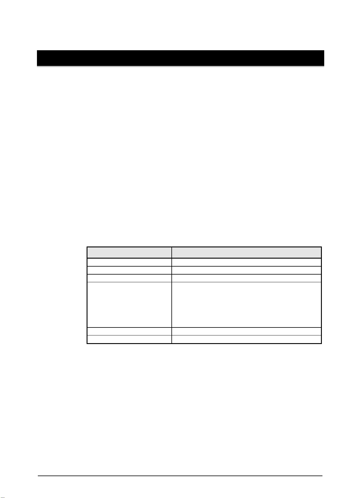
Table 1. VOIP-MG-H7 Card — Features
Feature Specification
Installed in: Master CU or single-side unit, CAG40D-M
Max no. of cards per cage 1
Location in cage Slot 13
Interface to IP network Electrical Ethernet 100/BaseT or 100/BaseF; Optical
Fast Ethernet (using an adapter installed on the cage
backplane)
Electrical/Optical Gigabit Ethernet through IP-UL-X
card
Ethernet Connector RJ-45
Control Protocols H.248 — VOIP-MG-H7 card
For information on the compatibility of the VOIP-MG-H7 card with other cards,
system software and management software, see “Compatibility” in the Card
Installation Overview.
Card Controls and Indicators
Card controls and indicators are shown in Figure 1, and described from top to
bottom in Table 2, Table 3 and Table 4.

Card Controls and Indicators
Page 2 April 2006
P/N 760-000596 Rev B
VOIP-MG PMC
VOIP-
MG-H7
Reset Button
FAIL
TEST
OK
ACTIVE
Figure 1. VOIP-MG-H7 Card — Controls and Indicators
Table 2. VOIP-MG-H7 Card — Control Descriptions
Control Action Description
Restart (RST/BU) RESET Reset Card
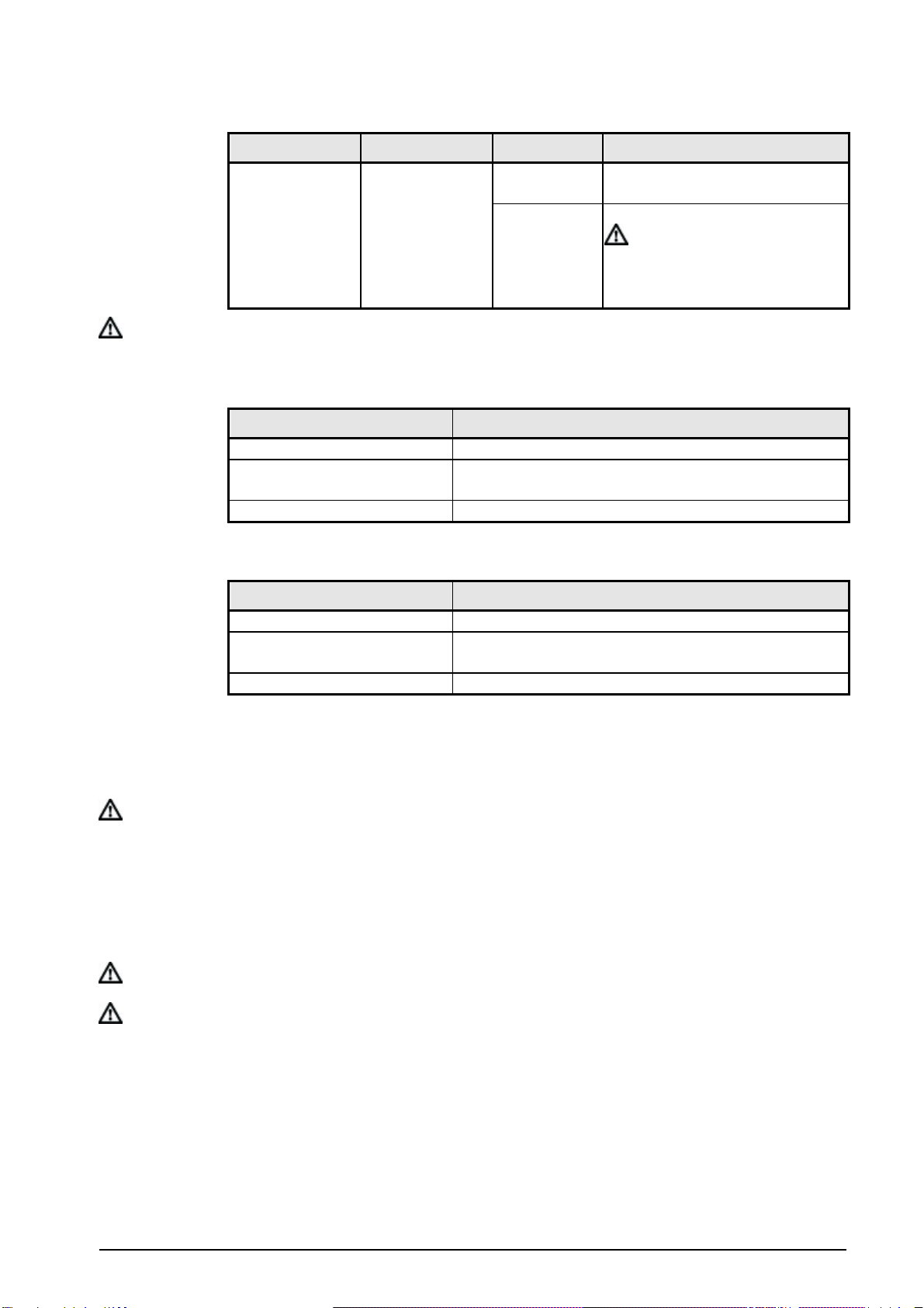
Table 3. VOIP-MG-H7 Card — Indicator Descriptions
Indicator Color Status Indication
OK Green LED ON Card operating normally
Fail Red LED ON Card failure, card reset or no
communication with CPT card
ON The gateway is enabled and
registered with the MGC
OFF The gateway is disabled
Active Green LED
Blinking The gateway is enabled but not
registered with the MGC
BroadAccess VOIP-MG-H7 Card - Installation Instructions
P/N 760-000596 Rev B April 2006
Page 3
Indicator Color Status Indication
ON Loopback or maintenance in
progress
Loop/Test Yellow LED
Blinking The card’s PMC is being burned.
Caution: Do not remove the
VOIP-MG-H7 card from the slot
or reset the card while the LED is
blinking.
Note: During power up, all indicators remain on until card completes initialization.
Table 4. VoP-MG ADP Backplane Adaptor — Connector Descriptions
Connector Type Description
P1 Ethernet RJ-45 Factory use only
P2 Ethernet RJ-45 Connector for Ethernet 100/BaseT uplink to IP network
or to IP-UL-x series card.
P3 Ethernet RJ-45 Not in use
Table 5. IP-ADP-OP-S Backplane Adaptor — Connector Descriptions
Connector Type Description
P1 Ethernet RJ-45 Factory use only
P2 Optical 100 FX SFP Connector for Optical Ethernet 100 BaseFX uplink to IP
network
P3 Optical 100 FX SFP Not in use
Configuration
There are no user configurable strapping options on this card.
Note: The VOIP-MG-H7 card is configured for use through the management software
provided with your system. For further details, see the BroadAccess
Configuration Guide supplied in the Service Manual and in the ClearAccess+
User Guide.
Installation
Note: System may remain powered while inserting card.
Caution: Modules can be damaged by electrostatic discharge (ESD). Before handling any
modules connect your wrist to an equipment ground using an approved anti-static
wrist strap. Ensure that all uninstalled modules are stored in anti-static packing
material. When working with modules, always place the module on an electrically
grounded approved anti-static mat.

Cables
Page 4 April 2006
P/N 760-000596 Rev B
Caution: Using excessive force when seating cards and modules into the backplane may
result in severe physical damage to the backplane pins or module connectors, and
if power is applied, may result in serious electrical damage to both the modules or
the backplane.
1. Place the grounded ESD wristband on your wrist.
2. Carefully remove card from package.
3. Slide the card into the master CU slot marked “13”.
Caution: Seat the card into the backplane by sliding it through the card guide while holding
the ejector ears open. Fully seat the card by pressing the ejector ears in until they
lock into place. Do not force the cards into the backplane. If excessive resistance
is felt, remove the card and check for proper alignment in card guides or
obstructions.
4. Install the VoP-MG ADP (for electrical uplink) or IP-ADP-OP-S (for optical
uplink) card backplane adaptor (supplied with the VOIP-MG-H7 card) on the
cage backplane connector which corresponds to the card slot in which the card
is installed (backplane connector P13).
5. If not already connected, connect cables to the cage as explained in “Cables”,
below.
Caution: If installing a new system, do not set the power cards main switch to ON until
system installation is complete, as described in the installation guide for your
specific cage.
Note: Verify that a compatible card (see “Compatibility” in the Card Installation
Overview) is installed in a suitable slot of the cage at the other end of the link,
then use the management software provided with your system to perform line
provisioning accordingly while the BroadAccess is in manual connection mode.
For further details, see the BroadAccess Configuration Guide supplied in the
Service Manual and in the ClearAccess+ User Guide.
6. After the CU/single-side unit, and RUs (where used) are installed, powered up,
and links are connected, verify that indicator status is as described in “Card
Indicators” above. Otherwise, refer to “Alarms and Troubleshooting” in the
BroadAccess Maintenance Guide supplied in the Service Manual and in the
ClearAccess+ User Guide.
Cables
Caution: Use caution when routing wires and cables. Avoid severe bending and routing
over sharp edges. Use grommet material when possible to avoid wear to cable
insulation.

BroadAccess VOIP-MG-H7 Card - Installation Instructions
P/N 760-000596 Rev B April 2006
Page 5
The uplink to the IP network is implemented using an optical Fast Ethernet uplink
cable, or using an electrical Ethernet 100/BaseT cable. The cable can be
connected either directly to the operator's IP network, or can be routed through the
system's IP-UL-x series card.
•For more information about connecting the Electrical Ethernet cable, see
Connecting the Electrical Ethernet Uplink Cable on page 5.
•For more information about connecting the optical uplink cable, see
Connecting the Optical Ethernet Uplink Cable on page 5.
Connecting the Electrical Ethernet Uplink Cable
1. Connect one end of the Ethernet Uplink cable supplied with the card to the
middle (marked P2) Ethernet Uplink connector on the VoP-MG-ADP card
backplane adaptor installed on the cage backplane.
2. Connect the other end of the cable to one of the following, depending on the
type of uplink used to the IP network:
directly to the operator’s IP network
to IP-UL-x series card backplane adaptor, P2 (middle) connector.
Connecting the Optical Ethernet Uplink Cable
1. Insert each connector on the IP-ADP-OP-S card backplane adaptor's middle
fiber optic connectors (marked P2) as follows:
a. Align the key on the male 100 FX SFP optical connector on the FO cable
with the slot on the female connector on the backplane adaptor.
b. Push it in until it clicks.
2. Connect the other end of the fiber optic cables to the operator’s IP network.
Table of contents
Popular Gateway manuals by other brands

LST
LST M500RFE-AS Specification sheet

Kinnex
Kinnex Media Gateway quick start guide

2N Telekomunikace
2N Telekomunikace 2N StarGate user manual

Mitsubishi Heavy Industries
Mitsubishi Heavy Industries Superlink SC-WBGW256 Original instructions

ZyXEL Communications
ZyXEL Communications ZYWALL2 ET 2WE user guide

Telsey
Telsey CPVA 500 - SIP Technical manual


