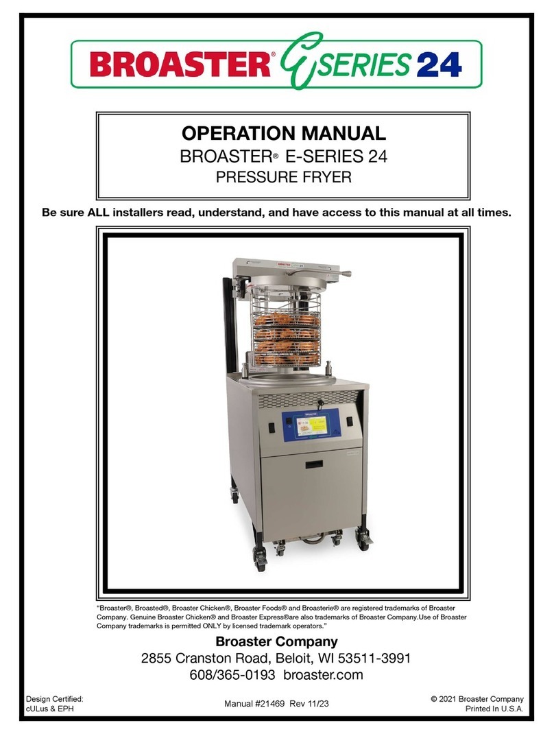
Broaster PERFECT HOLD HDM-4XP User manual

The Broaster Company
2855 Cranston Road, Beloit, WI 53511-3991
608/365-0193 www.broaster.com
Printed in U.S.A. Copyright 2005 The Broaster Company16287 2/09
MODEL HDM-4XP AND HDM-6XP
PERFECT HOLD™ DELI CASE
INSTALLATION/OPERATION MANUAL
Be sure ALL installers read, understand, and have access to this manual at all times.
“An American Tradition Since 1954!”


FOR YOUR SAFETY
Do not use or store gasoline or other flammable vapors
or liquids in the vicinity of this or any other appliance.
WARNING: Improper installation, adjustments, alteration, service or maintenance can
cause property damage, injury or death. Read the installation, operating and mainte-
nance instructions thoroughly before installing or servicing this equipment.
All adjustments and repairs shall be made
by an authorized Broaster Company repre-
sentative.
If there is a power failure, turn cook/filter
switch OFF. On the Model 1800GH, also
slide switch on gas valve OFF. DO NOT
attempt to operate unit during a power fail-
ure.
WARNING: Failure to read and
understand this manual completely
could result in serious injury or death. Be
sure ALL operators read, understand and
have access to this manual at all times.
WARNING: Rags or papers containing
cooking oil can catch fire if exposed to
heat. Laundering will not remove the oil. Dis-
pose of all oil-soiled papers and rags in a trash
container that is in a ventilated area away from
all cooking equipment or other heat sources
such as direct sunlight.
Manual #16287 9/05 Rev: 3/06
For the sake of safety and clarity, the following words used in this manual are defined as follows:
DANGER: Indicates an imminently hazardous situation which, if not avoided, could result
in serious injury or death.
WARNING: Indicates a potentially hazardous situation which, if not avoided, could result
in serious injury or death.
CAUTION: Indicates a potentially hazardous situation which, if not avoided, could result in
minor injury, property damage or both.


TABLE OF CONTENTS
1 - INTRODUCTION............................................................................................................1 - 1
DESCRIPTION............................................................................................................1 - 1
FEATURES .................................................................................................................1 - 1
2 - OWNER’S RESPONSIBILITY.......................................................................................2 - 1
3 - UNCRATING..................................................................................................................3 - 1
LIST OF PARTS..........................................................................................................3 - 1
Base Mounted Unit..............................................................................................3 - 1
Countertop Unit...................................................................................................3 - 1
INSTALLATION OF LOOSE PARTS...........................................................................3 - 1
Side Glass...........................................................................................................3 - 1
Back Doors..........................................................................................................3 - 2
Elements.............................................................................................................3 - 2
Pan Dividers (HDM-4 Shown).............................................................................3 - 2
4 - ELECTRICAL REQUIREMENTS ..................................................................................4 - 1
ELECTRICAL REQUIREMENTS................................................................................4 - 1
ELECTRICAL CHARACTERISTICS...........................................................................4 - 1
ELECTRICAL CONNECTIONS ..................................................................................4 - 1
Model HDM-4 Wiring Diagram............................................................................4 - 2
Model HDM-6 Single Phase Wiring Diagram......................................................4 - 3
Model HDM-6 Single Phase Wiring Diagram (effective BD6A40).......................4 - 4
Model HDM-6 Three Phase Wiring Diagram.......................................................4 - 5
Model HDM-6 Three Phase Wiring Diagram (effective BD6A40) .......................4 - 6
Model HDM-4XP Single Phase Wiring Diagram..................................................4 - 7
Model HDM-6XP Single Phase Wiring Diagram..................................................4 - 8
5 - GETTING TO KNOW YOUR DELI CASE .....................................................................5 - 1
Upper Control Panel (HDM-4 Shown).........................................................................5 - 2
Lower Control Panel (HDM-4 Shown).........................................................................5 - 2
Zones..........................................................................................................................5 - 2
6 - OPERATION..................................................................................................................6 - 1
SETTING CONTROLS................................................................................................6 - 1
CLEANING..................................................................................................................6 - 1
7 - MERCHANDISING HINTS.............................................................................................7 - 1
8- WARRANTY ...................................................................................................................8 - 1
Manual #16287 9/05


1 - INTRODUCTION
The Perfect Hold Deli Case is widely used in
supermarkets, convenience stores and
deli’s for reliable food holding and display.
This manual has been produced to provide
persons responsible for the operation and
maintenance of the equipment with a simple
but thorough understanding of its proper
use. We urge that this manual be thor-
oughly read and understood prior to placing
the deli case in operation.
As with any unit of food service equipment,
the deli case does require a minimum of
care and maintenance. Suggestions for
maintenance and cleaning are contained in
this manual and should become a regular
part of the operation of the unit.
Note: Before using, the deli case should be
thoroughly cleaned in accordance with the
instructions contained in this manual.
Should repair or adjustment of the unit
become necessary, we suggest that proce-
dures described in this manual be followed.
Or, if preferred, you may contact your local
Broaster Company representative or service
organization. You may also contact our
home office located in Beloit, Wisconsin.
It is our sincere desire that you obtain the
maximum benefit from your Perfect Hold
Deli Case. If at any time you have ques-
tions or require assistance, please do not
hesitate to contact us.
DESCRIPTION
The Perfect Hold Deli Case allows for food
products to be held at required tempera-
tures while maintaining their freshness and
quality. The deli case features “clear-view”
glass around the complete perimeter of the
serving area allowing for full view by the
customer.
FEATURES
• Holds a variety of pan configurations.
• Stainless steel trim.
• Easily accessible control panel.
• Main power switch.
• Recessed upper controls.
• Holding timers
• Heating elements removable for clean-
ing
1 - 1
Manual #16287 9/05


2 - OWNER’S RESPONSIBILITY
It is the owner’s responsibility to:
• Insure the deli case is properly main-
tained.
• Insure all warning signs are in their origi-
nal location and are legible.
• Allow only properly trained personnel to
operate, clean and maintain the warmer.
• Retain this manual for future reference.
• Insure main power supply is discon-
nected before the unit is serviced.
• Insure that all warning signs are intact
and legible and this manual is included
with the unit, when you sell, trade, dis-
pose of or give away your warmer.
If you need replacement warning signs or
manuals, contact an authorized Broaster
Company representative or The Broaster
Company at 608/365-0193.
2 - 1
Manual #16287 9/05


3 - UNCRATING
It is advisable to place the Perfect Hold Deli
Case as close as possible to its permanent
location prior to uncrating.
Each Broaster Perfect Hold Deli Case is
wood crated for protection during ship-
ment. Remove the top part of the crate first.
Next, remove the side crating panels. The
glass side panels, heating elements and
rear doors are wrapped in cardboard and
packed separately and must be installed.
LIST OF PARTS
Base Mounted Unit:
HDM-4 HDM-6 DESCRIPTION
11Base
1 1 Perfect Hold™ deli case
2 2 Side glasses
2 3 Long pan dividers (with holes)
6 8 Short pan dividers
2 2 Back doors
6 10 Display lamps
1 1 Operator Manual
0 1 Small Heating Element
1 1 Large Heating Element
Countertop Unit:
HDM-4 HDM-6 DESCRIPTION
1 1 Perfect Hold™ deli case
2 2 Side glasses
2 3 Long pan dividers (with holes)
6 8 Short pan dividers
2 2 Back doors
6 10 Display lamps
1 1 Operator Manual
0 1 Small Heating Element
1 1 Large Heating Element
After the top panel and side panels have
been removed, it is necessary to remove the
warmer from the skid which it was shipped
on. Cut the strapping to free the unit from
the skid.
INSTALLATION OF LOOSE PARTS
All glass on this unit is certified tempered
safety glass. The edges of this type of glass
are the most vulnerable to fracture. The
glass should be handled with extreme care
when installing.
Note: Glass panels should never be placed
with edges coming in contact with concrete
or other hard surfaces. The glass may chip
or break.
Clean all components and unit surfaces.
See CLEANING.
Side Glass:
1. Remove side cover (A) by pulling out-
ward on tab (B) then slide cover toward
the rear of the unit.
Continued:
3 - 1
Manual #16287 9/05


4 - ELECTRICAL REQUIREMENTS
ELECTRICAL REQUIREMENTS
CAUTION: Prior to connecting to the
power source, verify the voltage and
phase of the power source to which the unit
will be connected. Make sure that the
power source is identical to the power
requirements identified on the data plate on
the deli case. See chart below for neces-
sary requirements.
Note: Connection of the deli case to the
power source should only be done by a
qualified, licensed electrician.
Refer to the wiring diagram contained in
these directions when connecting to the
power source. The deli case must be ade-
quately and safely grounded. Refer to
local electrical codes and national electrical
code for correct grounding procedures.
ELECTRICAL CHARACTERISTICS
Be sure to check the wiring diagram. It
shows electrical circuits and connections.
• When installing or servicing the unit,
always check the dataplate to make cer-
tain proper parts are used and the cor-
rect service rendered. See rated values
in chart below. DO NOT apply a voltage
to the unit other than that shown on the
dataplate. If in doubt, consult your local
power company.
ELECTRICAL CONNECTIONS
• Turn unit OFF and disconnect main
power supply.
• A remote circuit breaker or fuse should
be installed in the main power supply
located in a path of exit and clearly iden-
tified.
• When installed, the unit must be electri-
cally grounded in accordance with local
codes, or in the absence of local codes,
with the National Electrical Code, ANSI/
NFPA 70, or for Canada, the Canadian
Electrical Code, CSA C22.2, as applica-
ble.
• Use copper wire only for connections.
• If power run is over 50 feet, use next
larger size wire.
• If no component operates, check main
power supply. Be sure main circuit
breaker is ON and main fuses are good.
DELI CASE MODEL VOLTS HZ WATTS AMPS PLUG CONFIG PHASE
HDM-4 -4 ft Complete Deli Case 120/240 60 2900 15 4-wire grounded 1 PH
HDM-4 -4 ft Countertop Deli Case 120/240 60 2900 15 4-wire grounded 1 PH
HDM-4 -4 ft Complete Deli Case 120/208 60 2900 16 4-wire grounded 1 PH
HDM-4 -4 ft Countertop Deli Case 120/208 60 2900 16 4-wire grounded 1 PH
HDM-6 -6 ft Complete Deli Case 120/208 60 4500 16 5-wire grounded 3 PH
HDM-6 -6 ft Countertop Deli Case 120/208 60 4500 16 5-wire grounded 3 PH
HDM-6 -6 ft Complete Deli Case 120/240 60 4500 15 5-wire grounded 3 PH
HDM-6 -6 ft Countertop Deli Case 120/240 60 4500 15 5-wire grounded 3 PH
HDM-6 -6 ft Complete Deli Case 120/208
120/240 60 4500 26
24 4-wire grounded 1 PH
HDM-6 -6 ft Countertop Deli Case 120/208
120/240 60 4500 26
24 4-wire grounded 1 PH
4 - 1
Manual #16287 9/05

WHITE
BLACKBLACK
WHITE
BLACK
WHITE
BLACK
WHITE
WHITE
BLACK
WHITE
BLACK
WHITE
RED
BLACK
RED
BLACK
RED
BLACK
RED
WHITE
WHITE
WHITE
WHITE
WHITE
WHITE
WHITE
WHITE
HI-TEMP
ELEMENT- 2000W
H1- TUBULAR HEATING
ORANGE
BLACK
L3
L1
208V
240V
120V 120V
N
F1 - 20AMP FUSE
F2 - 15 AMP FUSE
S1 - SWITCH, DPST
B1, B2 - BLOWER FAN
FL1-FL6 - FLOOD LIGHT
D1, D2, D3 - DIMMER
T1, T2, T3 - TIMER
TL1, TL2, TL3 - TIMER LIGHT
TH1 - THERMOSTAT
L1 - POWER ON LIGHT
L2 - HEAT ON LIGHT
H1 - LARGE TUBULAR HEATER
L1
L2
L3
N
F2
F1
L1
TH1
L2
TL1
TL2
TL3
FL1 FL2
FL3 FL4
FL5 FL6
B2
B1
D1
T1
T2
D2
T3
D3
Model HDM-4 Wiring Diagram:
4 - 2
Manual #16287 9/05

Model HDM-6
Single Phase Wiring Diagram:
T3 TL3
RED
D2 T2
BLACK BLACK
WHITE
BLACK
WHITE
BLACK
TL2
D1 T1 TL1
B1
BLACK
BLACK
WHITE
WHITE
BLACK
T4 T5
L2
WHITE
HI-TEMP WIRE
WHITE WHITE
WHITE
WHITE
WHITE
BLACK BLACK
REDRED
L3
REDRED
NL1 L3
WHITE
WHITE
FL9FL7
FL8
FL1 FL3
FL2
FL5
FL6FL4
BLACK
RED
FUSES 3
RED
HI-TEMP WIRE
RED
120V
TH2
TH1
ELEMENT- 2000W
H2- SMALL TUBULAR HEATER
H2-
RED
ORANGE
RED
L1
240V
L3 N
208V
120V
120/240V-1 PH
120/208V-1 PH
MODEL HDM-6
WIRING DIAGRAM
OR
TUBULAR HEATING
B3
RED
D5
ELEMENT - 1300W
TL5
D4 TL4
BLACK
WHITE
BLACK
BLACKBLACK
FL10
GND
ORANGE
BLACK
ORANGE
BLACK RED
2
ORANGE
1
L1
S1 - SWITCH, TRIPLE POLE SINGLE THROW
F1, F2, F3 - 20AMP FUSE
H1- LARGE TUBULAR HEATER
L2, L3 - T-STAT HEAT ON LIGHT
L1 - POWER ON LIGHT
TH1, TH2 - THERMOSTAT
TL1, TL2, TL3, TL4, TL5 - TIMER LIGHT
T1, T2, T3, T4, T5 - TIMER
D1, D2, D3, D4, D5 - DIMMER
FL1-FL10 - FLOOD LIGHT
B1, B2, B3 - BLOWER FAN
WHITE
BLACK
D3 B2
H1- TUBULAR HEATING
4 - 3
Manual #16287 9/05

4 - 4
Manual #16287 9/05
RED
D2 T2
BLACK BLACK
WHITE
BLACK
WHITE
BLACK
TL2
D1 T1 TL1
B1
WHITE
BLACK
WHITE
WHITE
BLACK
T4 T5
L2
WHITE
RED HI-TEMP WIRE
WHITE WHITE
WHITE
WHITE
WHITE
WHITE WHITE
REDRED
L3
REDRED
N
WHITE
WHITE
FL9FL7
FL8
FL1 FL3
FL2
FL5
FL6FL4
BLACK
ORANGE
FUSE
RED
RED HI-TEMP WIRE
ORANGE
WIRING DIAGRAM HDM-6 1 PH
120/208V, 1ph
TH2
TH1
S1 C1 - CONTACTOR
WHITE
BLUE
BLUE
YELLOW
ORANGE
ELEMENT- 2000W
H2- SMALL TUBULAR HEATER
H2-
ORANGE
RED
15883
ORANGE
L3 L2 L1
C1
120/240V, 1ph
TUBULAR HEATING
B3
RED
D5
ELEMENT - 1300W
TL5
D4 TL4
BLACK
WHITE
BLACK
BLACKBLACK
FL10
GND
RED
BLACK
BLACK
RED
ORANGE
1
L1
S1 - SWITCH, SPST
F1, F2, F3 - 20AMP FUSE
H1- LARGE TUBULAR HEATER
L2, L3 - HEAT ON LIGHT
L1 - POWER ON LIGHT
TH1, TH2 - THERMOSTAT
TL1, TL2, TL3, TL4, TL5 - TIMERLIGHT
T1, T2, T3, T4, T5 - TIMER
D1, D2, D3, D4, D5 - DIMMER
FL1-FL10 - FLOOD LIGHT
B1, B2, B3 - BLOWER FAN
BLACK
D3
WHITE
B2
H1- TUBULAR HEATING
T3 TL3
Model HDM-6 (EFFECTIVE BD6A40)
Single Phase Wiring Diagram:

TL3
ORANGE
D2 T2
BLACK BLACK
WHITE
BLACK
WHITE
BLACK
TL2
D1 T1 TL1
B1
BLACK
BLACK
WHITE
WHITE
BLACK
T4 T5
L2
WHITEWHITE
WHITE WHITE
WHITE
WHITE
WHITE
BLACK BLACK
RED
RED
L3
RED
RED
NL1 L2 L3
WHITE
WHITE
FL9FL7
FL8
FL1 FL3
FL2
FL5
FL6FL4
BLACK
FUSES 3
S1
RED RED
ORANGE
ORANGE
ORANGE
TH2
TH1
ELEMENT- 2000W
H1- TUBULAR HEATING ELEMENT - 1300W
TUBULAR HEATING
H2-
120/240v-3 PH
120/208v-3 PH
MODEL HDM-6
WIRING DIAGRAM
OR
240V
208V
L1 L2
208V
240V
N
L3
120V
120V
208V
240V
*CONNECT 240V WILD LEG
*TO L2 IF PRESENT
ORANGE
B3
RED
D5 TL5
D4 TL4
BLACK
WHITE
BLACK
BLACK
BLACK
FL10
GND
WHITE
BLACK
ORANGE
BLACK RED
2
ORANGE
1
L1
S1 - SWITCH, TRIPLE POLE SINGLE THROW
F1, F2, F3 - 20AMP FUSE
H1, H2, H3, H4, H5 - HEATER
L2, L3 - HEAT ON LIGHT
L1 - POWER ON LIGHT
TH1, TH2 - THERMOSTAT
TL1, TL2, TL3, TL4, TL5 - TIMER LIGHT
T1, T2, T3, T4, T5 - TIMER
D1, D2, D3, D4, D5 - DIMMER
FL1-FL10 - FLOOD LIGHT
B1, B2, B3 - BLOWER FAN
BLACK
D3
WHITE
B2
T3
Model HDM-6
Three Phase Wiring Diagram:
4 - 5
Manual #16287 9/05

BLUE
BLUE
YELLOW
BLACK
WHITE
BLACK
TL2
D1 T1 TL1
B1
WHITE
BLACK WHITE
WHITE
BLACK
T4 T5
L2
WHITE WHITE
WHITE
WHITE
WHITE
WHITE WHITE
RED
RED
L3
RED
RED
WHITE
WHITE
FL9FL7
FL8
FL1 FL3
FL2
FL5
FL6FL4
BLACK
WIRING DIAGRAM HDM-6 15887
RED RED
ORANGE
ORANGE
ORANGE
TH2
TH1
ELEMENT- 2000W
H1- TUBULAR HEATING ELEMENT - 1300W
TUBULAR HEATING
H2-
BLACK
GND
N
ORANGE
BLACK
120/240V, 3ph
120/208V, 3ph
C1
L3 L2 L1
ORANGE
RED
L1
S1 B1, B2, B3 - BLOWER FAN
C1 - CONTACTOR
FUSE 1
WHITE
ORANGE
B3
RED
D5 TL5
D4 TL4
BLACK
WHITE
BLACK
BLACK
BLACK
FL10
S1 - SWITCH, SPST
F1, F2, F3 - 20AMP FUSE
H1, H2, H3, H4, H5 - HEATER
L2, L3 - HEAT ON LIGHT
L1 - POWER ON LIGHT
TH1, TH2 - THERMOSTAT
TL1, TL2, TL3, TL4, TL5 - TIMERLIGHT
T1, T2, T3, T4, T5 - TIMER
D1, D2, D3, D4, D5 - DIMMER
FL1-FL10 - FLOOD LIGHT
BLACK
D3
WHITE
B2
T3 TL3
RED
D2 T2
BLACK BLACK
WHITE
Model HDM-6 (EFFECTIVE BD6A40)
Three Phase Wiring Diagram:
4 - 6
Manual #16287 9/05

F2
F1
L1
TH1
L2
TL1
TL2
TL3
B2
B1
D1
T1
T2
D2
T3
D3
L1
L2
L3
N
4 - 7
Manual #16287 9/05
Model HDM-4XP EXPORT

T2
TL2
D1
T1
TL1
B1
T4 T5
FL9FL7
FL8
FL1 FL3
FL2
FL5
FL6
FL4
ELEMENT- 2000W TUBULAR HEATING
ELEMENT- 1300W
H2-
B3
D5
H1- TUBULAR HEATING
TL5
D4 TL4
FL10
D3 B2
T3
TL3
D2
4 - 8
Manual #16287 9/05
Model HDM-6XP EXPORT
This manual suits for next models
1
Table of contents
Other Broaster Commercial Food Equipment manuals
Popular Commercial Food Equipment manuals by other brands

Bonnet Neve
Bonnet Neve COLISEUM UP User instructions

Delfield
Delfield F18DC48P-RCPR Original Instructions Installation, Operation and Maintenance Manual

Valley Sportsman
Valley Sportsman 009164625 user manual

Antunes
Antunes DCH-100 owner's manual

Angelo Po
Angelo Po 1G0FT1G Use and installation manual

Duke
Duke MUHC-51-120 Installation and operation manual