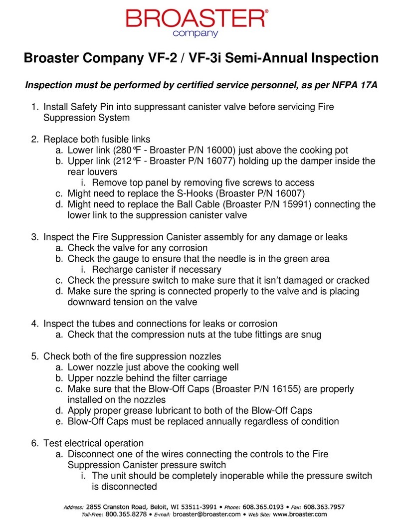
Broaster VF-2 Guide

© 2006 Broaster Company
Printed In U.S.A.
Be sure ALL installers read, understand, and have access to this manual at all times.
Broaster Company
2855 Cranston Road, Beloit, WI 53511-3991
608/365-0193 broaster.com
Genuine Broaster Chicken®, Broasted®, Broaster Chicken®, Broaster Foods®. and Broasterie® are registered
trademarks. Usage is available only to licensed operators with written authorization from the Broaster Company.
16501 7/06 Rev 10/22
SERVICE & PARTS MANUAL
BROASTER® VF-2 & VF3i
VENTLESS FRYER


W-1
All adjustments and repairs shall be made
by an authorized Broaster Company repre-
sentative.
If there is a power failure, turn cook/filter
switch OFF. On the Model 2400GH, also
slide switch on gas valve OFF. DO NOT
attempt to operate unit during a power fail-
ure.
2400GH: Post, in prominent locations,
instructions to be followed in the event that
the user smells gas. This information can be
obtained from your local gas supplier.
Failure to read and
understand this manual
completely could result in serious injury
or death. Be sure ALL operators read,
understand and have access to this
manual at all times.
Rags or paper containing
cooking oil can catch fire
if exposed to heat. Laundering will not
remove the oil. Dispose of all oil-soiled
papers and rags in a trash container that
is in a ventilated area away from all
cooking equipment or other heat
sources such as direct sunlight.
FOR YOUR SAFETY
Do not use or store gasoline or other flammable vapors
or liquids in the vicinity of this or any other appliance.
Improper installation, adjustments, alteration, service or maintenance can cause
property damage, injury or death. Read the installation, operating and mainte-
nance instructions thoroughly before installing or servicing this equipment.
For the sake of safety and clarity, the following words used in this manual are defined as follows:
Indicates an imminently hazardous situation which, if not avoided, could
result in serious injury or death.
Indicates a potentially hazardous situation which, if not avoided, could
result in serious injury or death.
Indicates a potentially hazardous situation which, if not avoided, could
result in minor injury, property damage or both.
broaster.com Manual #16501 7/06 Rev 2/15


i
TABLE OF CONTENTS
1 - ELECTRIC POWER SUPPLY ....................................................................................... 1 - 1
WIRING DIAGRAMS...................................................................................................1 - 2
VF2 ........................................................................................................................1 - 2
VF3i ....................................................................................................................... 1 - 6
VF2 EXPORT....................................................................................................... 1 - 10
VF3i EXPORT......................................................................................................1 - 13
2 - FRONT PANEL..............................................................................................................2 - 1
DUAL DISPLAY FAMILIARIZATION............................................................................ 2 - 1
OPERATIONAL LOCKOUTS ......................................................................................2 - 2
CONTROLLER BASIC PROGRAMMING...................................................................2 - 2
Normal Operating Mode...................................................................................... 2 - 2
Preset Cook Mode .............................................................................................. 2 - 3
Programming Procedure..................................................................................... 2 - 3
WARNING DISPLAYS.................................................................................................2 - 4
DISPLAY ACTUAL TEMPERATURE...........................................................................2 - 5
CALIBRATION ............................................................................................................ 2 - 5
ACCESS FOR SERVICE ............................................................................................ 2 - 5
FRONT PANEL ASSEMBLY........................................................................................2 - 6
DISPLAY BOARD (upper) ........................................................................................... 2 - 6
DISPLAY BOARD POWER INPUT........................................................................ 2 - 6
CONTROL BOARD (lower)......................................................................................... 2 - 7
CONTROL BOARD POWER INPUT .....................................................................2 - 8
SPEAKER ...................................................................................................................2 - 9
TRANSFORMER ...................................................................................................... 2 - 10
SMART TOUCH DISPLAY ........................................................................................ 2 - 11
3 - FIRE SUPPRESSION SYSTEM .................................................................................... 3 - 1
GENERAL DESCRIPTION.......................................................................................... 3 - 1
AUTOMATIC OPERATION ......................................................................................... 3 - 1
MANUAL OPERATION ............................................................................................... 3 - 1
INSPECTION & MAINTENANCE................................................................................ 3 - 1
Gaining Access ................................................................................................... 3 - 1
Monthly Inspection .............................................................................................. 3 - 2
Semi-Annually..................................................................................................... 3 - 2
Twelve Year.........................................................................................................3 - 3
SEMI-ANNUAL INSPECTION & MAINTENANCE LOG.............................................. 3 - 4
ACCESS FOR SERVICE ............................................................................................ 3 - 5
FIRE EXTINGUISHER REPLACEMENT .................................................................... 3 - 6
FUSIBLE LINK REPLACEMENT ................................................................................ 3 - 7
BREAK ROD REPLACEMENT ...................................................................................3 - 7
4 - COOKING AREA........................................................................................................... 4 - 1
ELEMENT SHAFT REMOVAL .................................................................................... 4 - 1
TEMPERATURE SENSOR PROBE............................................................................ 4 - 3
HI LIMIT CONTROL.................................................................................................... 4 - 4
HEATING ELEMENT................................................................................................... 4 - 6
broaster.com Manual #16501 7/06 Rev 10/20

ii
5 - ELECTRICAL COMPONENTS......................................................................................5 - 1
VF2 & VF3i
ACCESS FOR SERVICE....................................................................................... 5 - 1
MOTOR REPLACEMENT...................................................................................... 5 - 1
SWITCHES............................................................................................................ 5 - 3
MOTOR STOP SWTICH .................................................................................. 5 - 3
BASKET DOWN SWTICH................................................................................ 5 - 4
PRODUCT DOOR SWTICH.............................................................................5 - 5
AIR FILTER SWTICH .......................................................................................5 - 5
VF2
ACCESS DOOR SWTICH................................................................................ 5 - 6
ELEMENT UP SWTICH ................................................................................... 5 - 7
GREASE FILTER SWITCH .............................................................................. 5 - 8
PRESSURE SWITCH REPLACEMENT........................................................... 5 - 8
VF3i
ACCESS DOOR SWTICH................................................................................ 5 - 9
ELEMENT UP SWTICH ................................................................................. 5 - 10
GREASE FILTER SWITCH ............................................................................ 5 - 10
PRESSURE SWITCH REPLACEMENT......................................................... 5 - 12
6 - TROUBLESHOOTING................................................................................................... 6 - 1
ELECTRICAL TIPS .....................................................................................................6 - 1
INDICATOR LIGHTS................................................................................................... 6 - 2
SOLID STATE CONTROLLER TIPS........................................................................... 6 - 3
FROZEN IQF PRODUCT............................................................................................ 6 - 3
TROUBLESHOOTING FLOW CHART ....................................................................... 6 - 4
7 - PARTS ........................................................................................................................... 7 - 1
PANELS AND DOORS................................................................................................ 7 - 1
FILTER TRAY VF2 .................................................................................................... 7 - 2
VF3i..................................................................................................... 7 - 3
CONTROLLER AND COMPONENTS ........................................................................ 7 - 4
INTERLOCK SWITCHES AND ACTUATORS VF2..................................................... 7 - 6
VF3i....................................................7 - 9
CONTACTOR AND RELAY MOUNTING VF2........................................................... 7 - 11
VF3i .......................................................... 7 - 13
HEATING ELEMENT AND LIFT MECHANISM VF2 ................................................ 7 - 15
VF3i ............................................... 7 - 16
FIRE SUPPRESSION SYSTEM VF2 ....................................................................... 7 - 17
VF3i....................................................................... 7 - 18
BASKET LIFT MECHANISM.....................................................................................7 - 19
COOKING WELL GROUP ........................................................................................ 7 - 20
8 - PART NUMBER LIST .................................................................................................... 8 - 1
broaster.com Manual #16501 7/06 Rev 10/20

1 - ELECTRIC POWER SUPPLY
1-1
Many sections in this
manual pertain to check-
ing and repairing electrical components.
If no component operates, check main
power supply. Be sure main circuit breaker
is ON and main fuses are good.
Perform the following if unit will not turn on:
1. Disconnect main power supply.
2. Be sure all connections are tight. If
power supply is proper, see TROU-
BLESHOOTING section.
broaster.com Manual #16501 8/06 Rev 2/15

1-2
WHITE
BASKET LIFT CAM
SHORT
SWITCH
BASKET DOWN
SWITCH
UP & DOWN
PIN LONG
PIN
M
NO
NC
C
GEAR MTR
PRE SSU RE SEN SOR
P
FTLAU DFL
MICROPNEUMATICLOGICIN K
MPL
GEAR MTR
RELAY
HIGH LIMIT RELAY
12VDC
C
COIL
NC
NO
C1 ON/OFF
RELAY
12VDC
COIL
C
NC
NO
RED
SPEAKER
HEATER
L3
C1 240V COIL
L1
L2
208 OR 240V
T3
L3
T3
T1T2
C2 120V COIL
L1
T1T2
L2
120V
HI LIMIT
MANUAL RESET BUTTON
PROBE
FAN ON/OFF
12VDC
COIL
C
NC
NO
RELAY
WIRING DIAGRAM
MODEL VF2
PURPLE
YELLOW
BLACK
34
12
BLK
24
BLK
23
22 21
BLUE
BLUE
ELEMENT UP
SWITCH
17
BLUE
BLUE
16
10
GREASE FILTER
SWITCH
AIR FILTER
SWITCH
AIRFLOW
SWITCH
PRODUCT DOOR
SWITCH
ACCESS DOOR
SWITCH
BLUE
15
6
BLK
9
11
8
14
13
7
5
4
26
BLK
WHT
30
BLK
WHT
25
WHT
2
1
29
SLEEVE
BLK
41
32
BLK
42
10
SLEEVE
27
1
PURPLE
BLK
RED
FIRE
SUPPRESSION
SWITCH
BLK
BLK
31
RED
35
RED
BLUE
SLEEVE
37
FAN
BLUE
40
WHITE
44
39
BLUE
WHITE (neutral)
RED
GREEN
BLK
POWER
120/208V OR 120/240V
1 PH 60 HZ
4 WIRE W/ GROUND
AND NEUTRAL
FIELD WIRING
BY OTHERS
BLK
38
HEATER CONNECTOR BOX
ARC
SUPPRESSOR
A
23
18
1314
14
58 912
24
24
23
33
30
33
30
22
21
22
21
26
27
29 31
28
20
20
19
18
17
16
13
25
39
40
38
38
24
25
3
37
68
1 2 43 5 6 87 9
PROBE
28
43
25
WHITE
19
44
RED
BLK
BLK
TBC-FC448-010
THERMO-
(-) (+)
RED YEL
TYPE K
TBC-FC448-010
COUPLE
C1
SPKR
INPUT
+24 VAC
HEATER
FAN
14
16500
INDICATOR LIGHT
12
15
ARC
SUPPRESSOR
WIRING DIAGRAM VF2:
broaster.com Manual #16501 8/06 Rev 2/15

1-3
WIRING DIAGRAM VF2: effective S/N VF2F70041x
NO
NC
C
PRES SURE SE NSO R
P
MPL
broaster.com Manual #16501 8/06 Rev 2/15

1-4
WIRING DIAGRAM VF2: effective S/N VF2F90XXXX
NO
NC
C
PRES SUR E SENS OR
P
MPL
broaster.com Manual #16501 8/06 Rev 2/15

1-5
WIRING DIAGRAM VF2: effective S/N VF2L90XXXX
NO
NC
C
broaster.com Manual #16501 8/06 Rev 2/15

1-6
WIRING DIAGRAM VF3i:
NO
NC
C
PRES SUR E SENSO R
P
MPL
broaster.com Manual #16501 8/06 Rev 2/15

1-7
WIRING DIAGRAM VF3i: effective S/N VF3G900320
NO
NC
C
PRESS URE SE NSOR
P
MPL
broaster.com Manual #16501 8/06 Rev 2/15

1-8
WIRING DIAGRAM VF3i: effective S/N VF3H90XXXX
broaster.com Manual #16501 8/06 Rev 10/20

1-9
WIRING DIAGRAM - VF-3 / VF-2 effective S/N VF3J02112 and VF2_02003G
broaster.com Manual #16501 8/06 Rev 10/20

1-10
WIRING DIAGRAM VF2 EXPORT:
NO
NC
C
PRESSUR E SENS OR
P
MPL
broaster.com Manual #16501 8/06 Rev 2/15

1-11
WIRING DIAGRAM VF2 EXPORT: effective S/N VF2F90XXXX
NO
NC
C
PRESSU RE SEN SOR
P
MPL
broaster.com Manual #16501 8/06 Rev 2/15

1-12
WIRING DIAGRAM VF2 EXPORT: effective S/N VF2L90XXXX
NO
NC
C
broaster.com Manual #16501 8/06 Rev 2/15

1-13
WIRING DIAGRAM VF3i EXPORT:
NO
NC
C
PRESS URE SEN SOR
P
MPL
broaster.com Manual #16501 8/06 Rev 2/15

1-14
WIRING DIAGRAM VF3i EXPORT: effective S/N VF3F90XXXX
NO
NC
C
PRESS URE SE NSO R
P
MPL
broaster.com Manual #16501 8/06 Rev 2/15
Other manuals for VF-2
2
This manual suits for next models
1
Table of contents
Other Broaster Commercial Food Equipment manuals
Popular Commercial Food Equipment manuals by other brands

B+S
B+S NC Series Installation, operating and servicing instruction manual

HURAKAN
HURAKAN HKN-RH2 manual

Henny Penny
Henny Penny Evolution Elite EEE-141 quick guide

Diamond
Diamond SNE/RN-B7-R2 Instructions for installation and use

Hussmann
Hussmann austral DO13-1 Series installation manual

Tetra Pak
Tetra Pak HOYER COMET N manual