Brofer MDF 25 Operating instructions

MDF 25
MANUALE DI INSTALLAZIONE E D’USO
INSTALLATION AND OPERATION MANUAL
AIR ENGINEERING
PROTEZIONE INCENDIO
FIRE PROTECTION

7
FIRE DAMPERS
CERTIFIED ACCORDING TO EN 15650
SERIES MDF 25
CONTENTS
SPECIFICATIONS/GENERAL INFORMATION pag 7
NORMATIVE REFERENCES 7
PRECAUTIONS FOR HANDLING AND INSTALLATION 8
MAINTENANCE 8
WALL INSTALLATION 8
OPERATING CONTROLS 9
MECHANICAL FUSE REPLACEMENT 10
OPERATION DATA AND WIRING MANUAL CONTROLS 11
OPERATION DATA AND WIRING MOTORIZED CONTROLS 11
SPECIFICATIONS/GENERAL INFORMATION
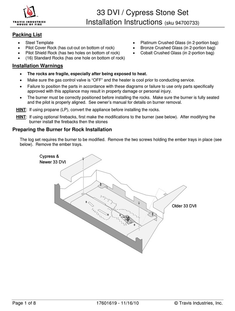
Fire damper suitable for installation on a wall, made from duct and galvanized steel components , calcium silicate
blade mono slab sp. 25 mm with perimeter seals to ensure sealing requirements to cold and hot smoke. The control
device ( manual with electromagnetic release or motorized ) consists of a plate removable and replaceable even after
installation, on which they are installed all the elements necessary for the proper operation and functioning of the fire
damper; the particular geometry of the control mechanism, prevents that the pressure present in the duct (up to 500
Pa) opening the blade if not acting directly from the reset lever. When installation is completed, the command will be
out of the masonry simplify any post-installation actions. The dampers, installed according to the instructions in this
manual , are used in HVAC systems by restoring the partitioning between two rooms, ensuring perfect insulation from
heat and smoke seal.
The installer has the obligation to follow the installation procedures and use of the equipment described in this
manual, in order to comply with the same conditions as the samples to be tested. Any deviation from the instruc-
tions, affect the validity of the certification of the product and the declaration of correct installation
NORMATIVE REFERENCES
Fire dampers tested according EN 1366/2 and classified according to EN 13501/3
CLASSIFICATION OF RESISTANCE
SUPPORT EI 120 S - 500 Pa EI 90 S - 500 Pa
LOW DENSITY RIGID WALL
SP.MIN. 100
(Vei o) da 100x200 a 800x600 MA / SE da 100x200 a 800x600 MA / SE
Legenda
E = integrity I = thermal insulation S = smoke seal
Ve= vertical installation ho= horizontal installation io = side exposed to fire indifferent
MA = manual reset device SE = device with servomotor
ITENG

8IT ENG
PRECAUTIONS FOR HANDLING AND INSTALLATION
CAUTION!
• All operations of handling and installation shall be made with the blade of the fire damper in the closed position
(our standard delivery).
• All operations of connection power line must be performed by qualified service personnel.
• Keep clean the connecting end from residues of cement to securely connect the rest of the duct
• Avoid any deformation of the duct and / or obstacle inside the duct which may prevent the successful rotation of
the blade
• Check that there are no external obstacles (cables, pipes, etc. ..) to prevent the correct operation of the controls
outside of the duct
• Keep the most accessible as possible to the control side in order to ensure the necessary space usage and mainte-
nance of the damper.
MAINTENANCE
Is advisable to periodically run a check the correct operation of the actuating and signal the damper. In particular,
check the correct and complete opening and closing of the blade: for the operation of the controls follow the instruc-
tions listed “CONTROL OPERATION.” Also check that the warning devices at the beginning and ending are in good
condition and working properly.
DIMENSIONAL
WALL INSTALLATION
• 1 - Before proceeding with the installation, verify the integrity of the damper,
the correct positioning of the blade in the closed position and the operation of
the command.
• 2 - Provide support having an opening on the increased size of 50 mm from the
nominal dimensions of the damper.
• 3 - Fold in hand the four
mounting brackets.
• 4 - Position the damper inside
the opening.
• 5 - Observe
the protru-
sions shown
in Table 1
so that the
rotation axis
of the blade
is perfectly
centered to
the support.

9
ITENG
After installation you need to perform a
function test verifying the correct rota-
tion of the blade and the efficiency of
the control (manual or motorized).
• 7 - Make a frame on the drive
side using strips plasterboard
of thickness 12.5 mm. Keep the
strips adjacent to the damper.
• 6 - Attach the damper to the
wall using the brackets and
using a suitable fixing to the
support.
OPERATING CONTROLS
Manual reset device
Reset:
• From the unlocked position (fig. 4), where the indicator on the reset lever is positioned on the symbol] - [ rotate the
lever clockwise 90 degrees making sure that the command locks in the open position (fig. 5 ), the indicator lever is
positioned on the symbol] I [.
Manual opening (test):
• Act on the button shown in fig.6.
Manual control with electromagnet
Reset:
• Activate the state of the electromagnet opening and closing the power circuit of the same depending if the model of
electromagnet is normally energized or de-energized
• Lift the metal lever (fig. 7 / fig. 8) on the cover of the control unit until it stops.
• Reset the damper as shown in the previous section
Manual opening (test):
• Operate the test button shown in fig.6
Closure normally energized electromagnet:
• Power the electromagnet (to perform a function test unhook the power supply).
Closure normally de-energized electromagnet:
• Switch off the power of the electromagnet (to perform a function test hook the power supply).
fig. 4 fig. 5 fig. 6
fig. 7 fig. 8

10 IT ENG
Operation with servo motor
Reset:
• Insert into the slot on the servomotor appropriate key supplied and turn it clockwise until the indicator in position
90 °
• Perform a fast rotating counterclockwise to lock the actuator in the open position
Manual opening (test):
• Insert into the slot on the servomotor appropriate key supplied and turn it counter-clockwise approximately ½ turn
in order to engage the return spring that will bring in automatic servo motor in the closed position and the indicator
at 0 ° position
Motorized opening (test):
• Turn the lever on the thermoelectric fuse located next to the servomotor or disconnect power.
MECHANICAL FUSE REPLACEMENT
CAUTION!
All operations of connection or maintenance must be carried out with the damper closed and de-energized.
Operation
Fuse replacement is required every time the peak temperature within the duct, has exceeded the specified degrees
Celsius on the same fuse. A tab shows the status of the fuse (fig. 9), when the body disappears into the plastic fuse
holder (fig. 10), it is necessary to replace the fuse.
Procedure:
• Make sure the damper is unarmed
verifying visibly that the indicator on
the lever indicates the symbol] - [on
the carter. Otherwise, act on the test
button to manually open the damper.
• Remove the clear plastic cover by
unscrewing the central fixing screw
(fig. 11)
• Unscrew the 2 screws and remove the
release mechanism from the plate.
• Replace the fuse by compressing the
spring and hooking the two protrud-
ing pins (fig. 12)
fig. 9 fig. 10
fig. 11
fig. 12
Central fixing screw
Fixing screw
release mechanism
Clear plastic cover

11
ITENG
fig. 12
OPERATION DATA AND WIRING MANUAL CONTROLS
Microswitches start and end of stroke
The signaling devices stroke end FCU and beginning stroke DCU are both
switches with two contacts independent of the type NC + NO.
The first normally closed (NC) contacts 1 and 6, while the second normally
open (NO) contacts 2 and 5.
At the click of the switch contact status is reversed, the NC contact opens and
the NO contact closes.
Ex: contacts 1 and 6 (NC) is connected to the relay that controls power to the
fan, while contacts in 2 and 5 (NO) is connected to a warning light alarm. In
this case the closure of the damper, the fan will turn off and turn on the light.
Technical data of the switches
-Cable section: 2.5 mm ² rigid - flexible with ferrule 1.5 mm ² Operating tem-
perature: from - 25 °C to + 70 °C
Electromagnet device
If necessary, you can equip the damper of an electromagnet that allows you
to anticipate the closing of the damper with respect to the intervention of the
thermal fuse. Depending on the type of electromagnet (normally energized or
de-energized), sending or interrupting the electrical signal power, the damper
will close preventing the diffusion of cold smoke.
In case of fire, the raising of the temperature, the thermal fuse has priority of
action compared to the electromagnet.
Technical data of the magnets
-Holding force: 120N
-Degree of protection (En 60529): IP40
-Power consumption at 20 ° C: 1.6 W (lack) - 3.5 W (output)
-Operating Temperature: -30 ° C to +85 ° C
OPERATION DATA AND WIRING MOTORIZED CONTROLS
The operation of the motor is given by the connection to the electricity network
(contacts 1 and 2) which brings the blade of the damper in the open posi-
tion and simultaneously charging the internal spring which stores the force
required to close the duct in case of alarm or black- outs.
The connection of the two switches inside the motor can make flexible the
rest of the system. For example, by connecting the contacts S1 and S2 will
be possible in the event of closure of the damper, can shut down the unit for
ventilation, while the contacts S4 and S6 turn on a warning light.
The thermoelectric device is composed of three fuses: Fire dampers then be-
come sensitive to the temperature inside the duct (with fuses Tf and Tf 2 3
which can be substituted) and the ambient temperature (Tf with fuse 1).
The device cuts off in an irreversible way, if not replacing the fuses , the sup-
ply line so that the servomotor leaving overs, with the spring force, the blade
in the closed position.
It also has a manually operated key that simulates the operation of the fuses
allowing testing of the damper.
Its position outside the damper and fastening with screws allows a safe tem-
perature control and easy maintenance.
-24V Connection: transformer
-230V Connection: for the interruption of
the network must incorporate a device
which disconnects the phase conductors
(contacts opening min. 3mm)
Table of contents
Popular Fireplace Accessories manuals by other brands

Valor
Valor H3 Series installation manual

IHP
IHP SEREFINA CI1500 GCK LP installation instructions

Dimplex
Dimplex RLG20BR owner's manual

Valor
Valor LX2 Series installation manual

pleasant hearth
pleasant hearth PH32DR installation manual

Lennox Hearth Products
Lennox Hearth Products 36ABF installation instructions

Valor
Valor 738JL installation instructions

Vermont Castings
Vermont Castings TrimWorks 36DVBGTKCB installation instructions

Gimeg
Gimeg Cosi square glass set M installation instructions

Travis Industries
Travis Industries DVL GSR quick start guide

Masport
Masport Riverstone instructions

Northline Express
Northline Express MR. FLAME GLASS SCREEN owner's manual