brookfield NB-2000HD2 Door Operator Installation Instructions
Although each Door Operator has been fully inspected and tested prior to shipment, assure that
no physical damage has occurred during shipping and handling.
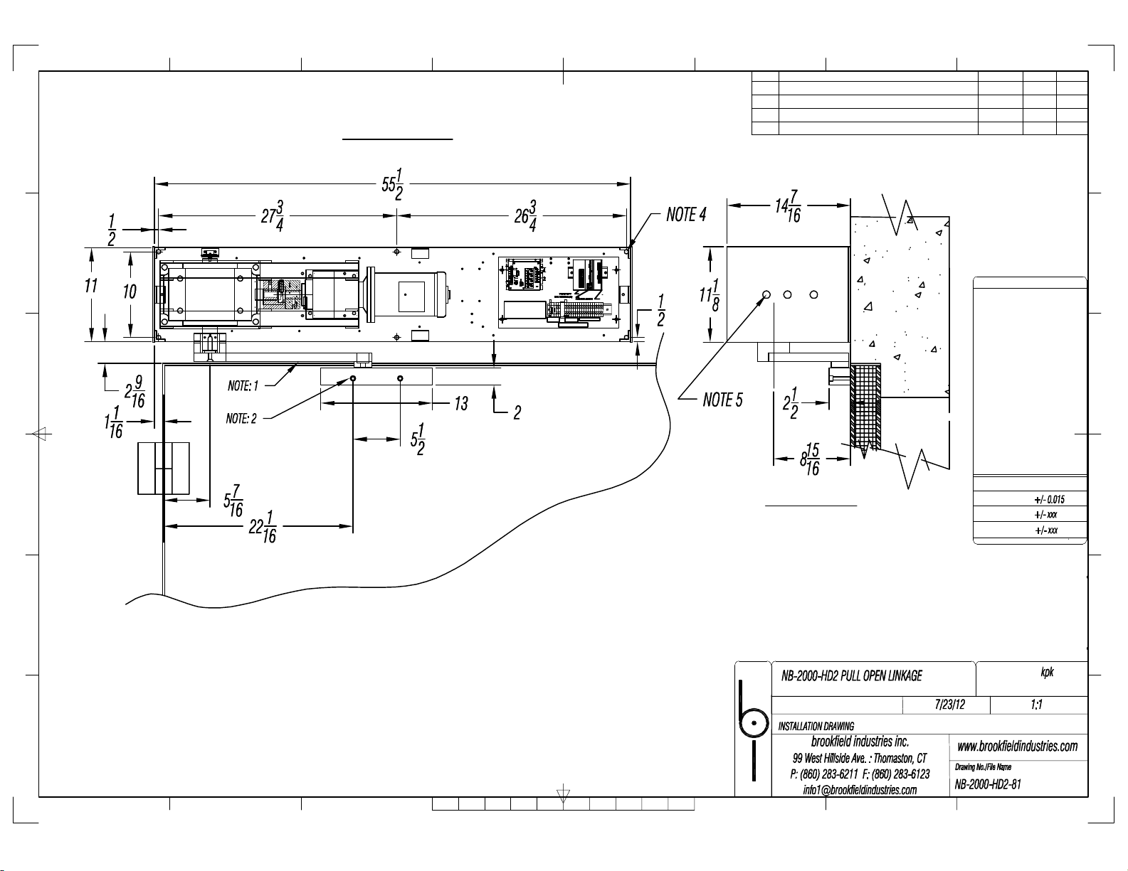
1. Position Door Operator in the horizontal and vertical directions as indicated on installation drawing
NB-2000-HD2-81 for pull open applications.
Locate Slider Block assembly on door as shown on installation drawing NB-2000-HD2-81 for pull
open applications. For Push Open applications refer to drawings: NB-2000-HD2-86, -87
2. Mount Door Operator base plate with (6) 3/8”diameter Grade 5 bolts and tighten properly (not
included). For pull open application, weld Mounting Block directly to door as indicated or bolt
Slider Block directly to door with (2) 3/8”diameter socket head cap screws (included). For push
open application, mount the door attachment pivot with (2) 3/8” diameter grade 5 bolts and properly
tighten with lock washers.
3. With Linkage Arm disconnected, measure force near the lock edge of the door to accelerate the
door to opening and closing speeds. This force, times the distance to the hinge pin centerline shall
not exceed the Rated Operating Torque of 6000 lb-in.
4. Check Linkage Arm to assure it doesn’t interfere with the door or Slider Block. In addition, make
sure cam follower (of Linkage Arm) is properly engaged in Slider Block. Proper engagement is
defined as full engagement (–1/16”) max.
5. With Linkage Arm connected and power removed, measure force to open door/ backdrive (at
constant velocity). This force must be £ 50 lb (per UL 325 section 29.3) and be applied near the
lock edge of the door.
6. All PLC and Motor Control settings have been preset by brookfield industries, inc.; however, we
recommend these values be double-checked with the Parameter sheet supplied.
7. Install activation switches or push button stations: (a) within sight of the door, (b) at a minimum
height of 5’ so small children cannot reach and (c) away from moving parts of the door.
8. Before wiring 115 AC supply voltage to operator, assure power is disconnected and all “Lock-Out”
Safety Procedures have been strictly adhered to.
9. Connect 115 VAC and class (2) 24 VDC wiring as shown on Terminal Strip Hookup Legend and
Wiring Diagrams. Disconnect “Lock-Outs” and turn on breakers.
10. Assure speed trimpots on Multi-Speed Board (Presets 1-4) are in the 25% range before activating
operator.
11. Make sure that all Safety Instructions and Warnings have been followed.
12. Activate Open, Partial Open and Close commands.
13. Adjust Presets 1-4 clockwise until the minimum opening and closing times listed in Table 1 have
been obtained.
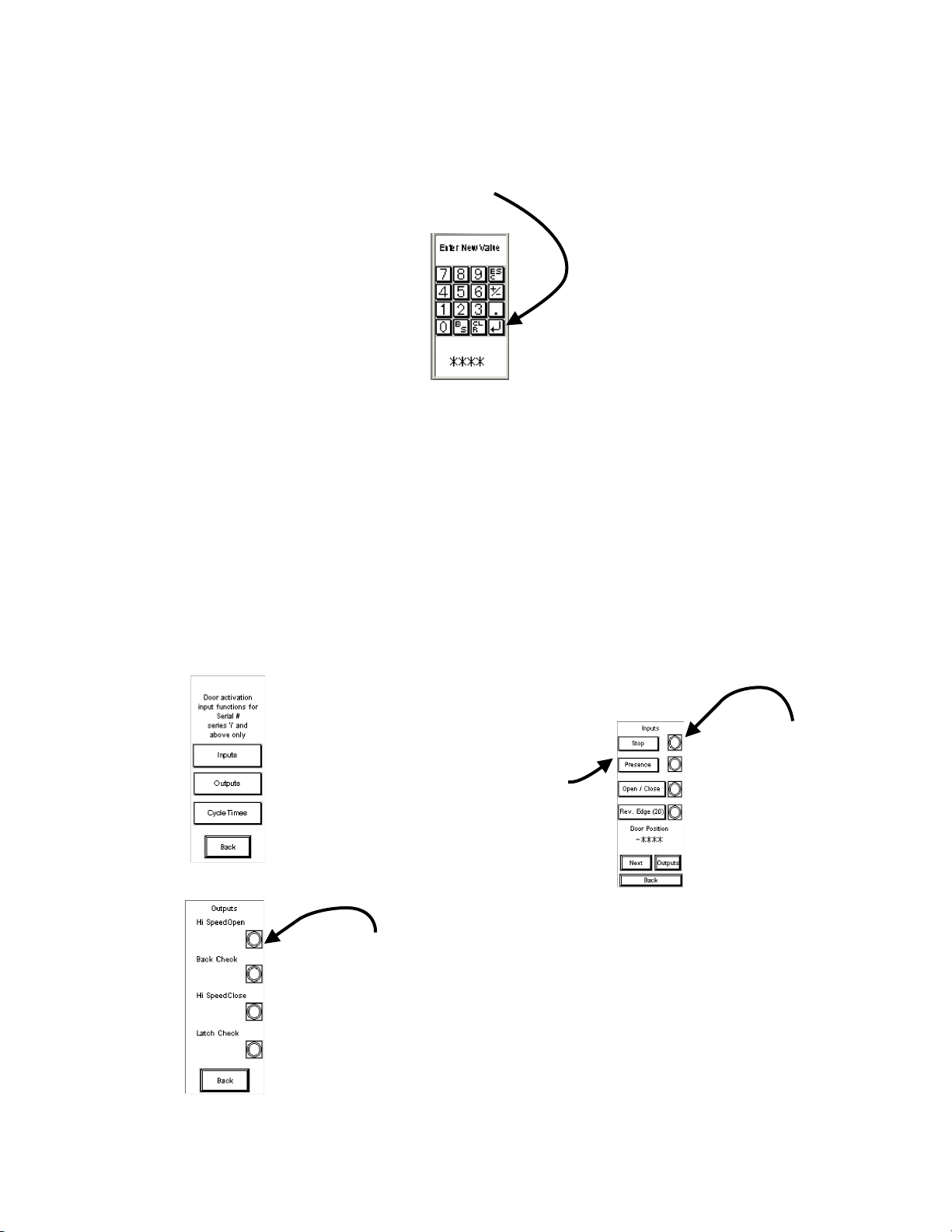
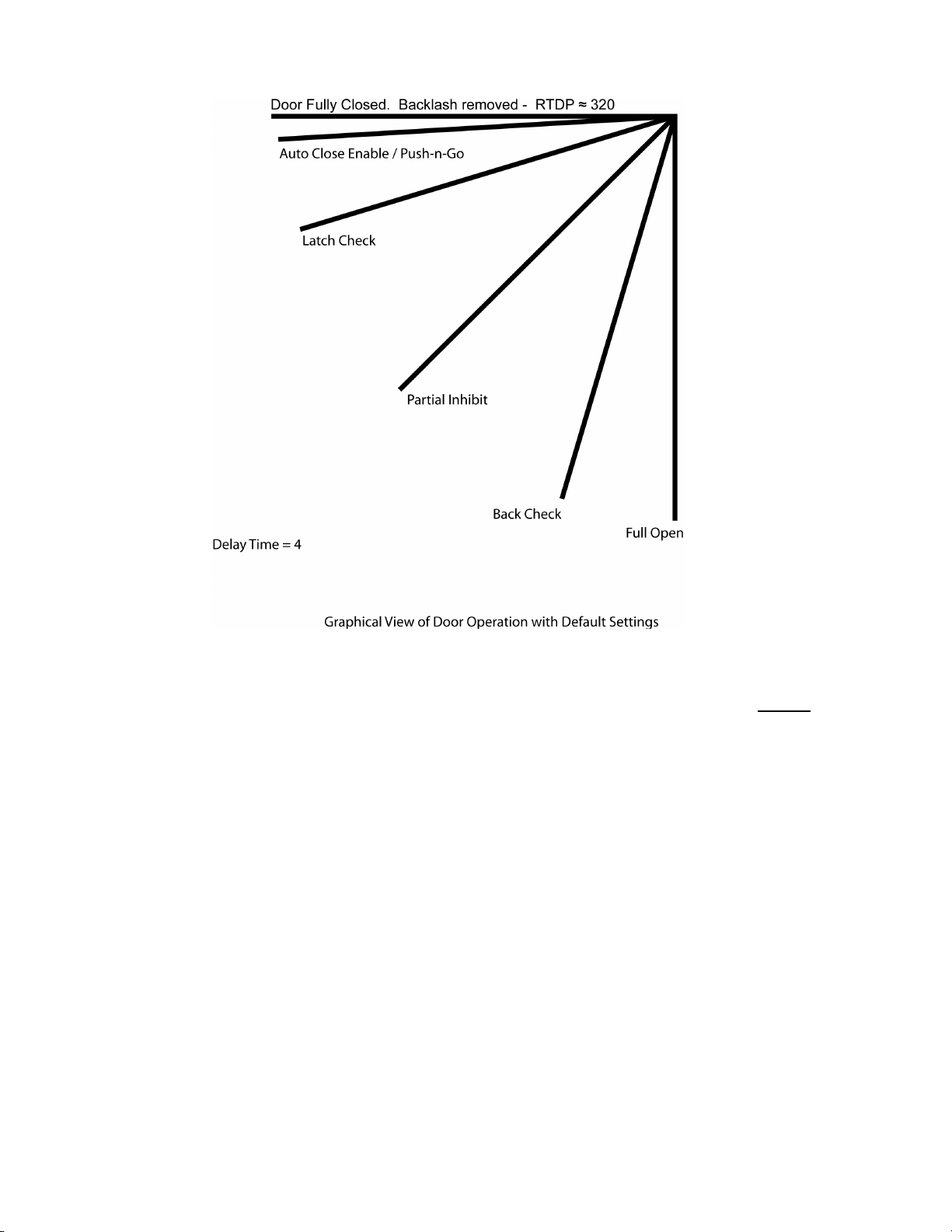
14. Adjust Door Position factory presets as required using the DAU. Refer to the DAU Instruction,
Door Position Setup Instructions and Parameters as required.
15. Check and adjust, if necessary, the trimpot settings (refer to the Parameter sheet) on the Motor
Control.
16. Check Entrapment Protection in both directions. This is accomplished by measuring the force
that prevents a stopped door from moving in a particular direction and can be accomplished with a
simple force gage. This force must be ≤40 lbs and is applied at the latch side per UL 325 section
29.4 Entrapment. When measuring this force be careful not to erroneously measure the inertia
force of the door. This can be accomplished by first stopping the door without the gage, then
substituting the gage with the minimum force to keep the door from moving in that particular
direction. This force is adjusted by varying the FCL and RCL trimpots settings on the Motor
Control.