manuals.online logo
Brands
  1. Home
  2. •
  3. Brands
  4. •
  5. Brooks
  6. •
  7. Air Compressor
  8. •
  9. Brooks 8600 User manual

Brooks 8600 User manual

Other manuals for 8600

2

This manual suits for next models

2

Other Brooks Air Compressor manuals

Brooks 8600 User manual

Brooks

Brooks 8600 User manual

Brooks 8600 User manual

Brooks

Brooks 8600 User manual

Brooks 8200 User manual

Brooks

Brooks 8200 User manual

Brooks CTI-Cryogenics Manual

Brooks

Brooks CTI-Cryogenics Manual

Popular Air Compressor manuals by other brands

Craftsman 919.724591 owner's manual

Craftsman

Craftsman 919.724591 owner's manual

Atlas Copco GA 30+ Instruction book

Atlas Copco

Atlas Copco GA 30+ Instruction book

Hitachi Highly WHP11500VSDPC9EQ installation manual

Hitachi

Hitachi Highly WHP11500VSDPC9EQ installation manual

Craftsman 919.167810 owner's manual

Craftsman

Craftsman 919.167810 owner's manual

Yamato 24/2 M1CD instruction manual

Yamato

Yamato 24/2 M1CD instruction manual

Clarke 2242117 Operation & maintenance instructions

Clarke

Clarke 2242117 Operation & maintenance instructions

Sparmax DC-25XR user manual

Sparmax

Sparmax DC-25XR user manual

Briggs & Stratton Air Compressor Operator's manual

Briggs & Stratton

Briggs & Stratton Air Compressor Operator's manual

Fini F3GST2TK Operator's manual

Fini

Fini F3GST2TK Operator's manual

Campbell Hausfeld RP3300 Easy setup guide

Campbell Hausfeld

Campbell Hausfeld RP3300 Easy setup guide

Ingersoll-Rand UP6 20 HP Option manual

Ingersoll-Rand

Ingersoll-Rand UP6 20 HP Option manual

Parkside PKO 270 A1 operating instructions

Parkside

Parkside PKO 270 A1 operating instructions

Clas Ohlson QIE-ZTH-15 manual

Clas Ohlson

Clas Ohlson QIE-ZTH-15 manual

Ferm CRM1046 Original instructions

Ferm

Ferm CRM1046 Original instructions

BE AC153 Operation manual

BE

BE AC153 Operation manual

RIDGID OF25150A Operator's manual

RIDGID

RIDGID OF25150A Operator's manual

Johnson Controls QUANTUM LX Setup

Johnson Controls

Johnson Controls QUANTUM LX Setup

Ring Automotive RAC700 instructions

Ring Automotive

Ring Automotive RAC700 instructions

manuals.online logo
manuals.online logoBrands
  • About & Mission
  • Contact us
  • Privacy Policy
  • Terms and Conditions

Copyright 2025 Manuals.Online. All Rights Reserved.

4 Copyright 2013, Brooks Automation Inc Part Number 8040705, Revision A, 01/11/2013 ECO Number 63723 Brooks Automation Inc www.brooks.com Printed in U.S.A 1
800-367-4887 USA
978-262-2400 International
Troubleshooting
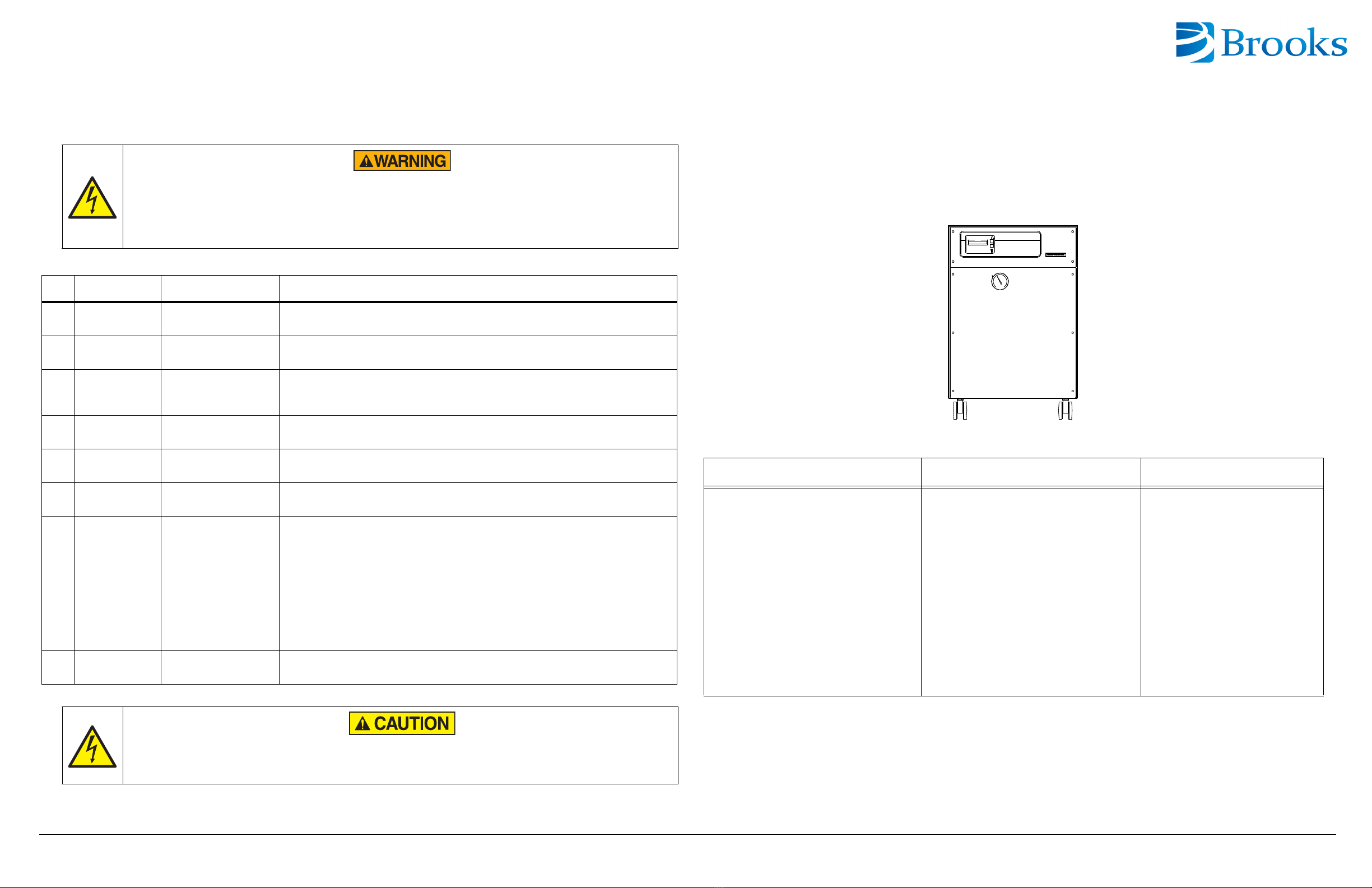
Look in Table 1 to find the error message that is displayed on the 8600 Compressor elapsed time meter/error message
display. Press the RESET switch to cancel the failure signal, and the status display will show the elapsed time. If the
failure message is not cancelled when the RESET switch is pressed, wait fifteen minutes and press the RESET switch
again. If the thermal switch operates, it takes about 15 minutes to reset. For more detailed information, see the Cryo-
Torr ®8600 Compressor Installation, Operation and Maintenance Manual (8040707). 8600 Compressor
Quick Installation Guide
Part Number 8040705, Revision A, 01/11/2013
ECO Number 63723
High Voltage
Disconnect the 8600 Compressor from its power source before performing any troubleshooting procedures.
The 8600 Compressor pump is hot after operating. Wait for the pump to cool down before working on the inside
of the compressor. Do not change or modify any 8600 Compressor internal wiring circuits, this may cause
failure of the compressor and cold head due to improper phasing.
Table 1: 8600 Compressor Troubleshooting Procedures
No. Message Possible Cause Corrective Action
1. Cooling Water Thermal switch (TS3)
operates. Check the cooling water requirements.
2. Low Pressure Low pressure switch
(LPS) operates. Add helium gas.
3. Overload Overcurrent relay (TS)
operates.
1. Check the power source requirements.
2. Check the cooling water and ambient temperature.
3. Check the static helium pressure.
4. Others Thermal switch (TS1 or
TS2) operates. Contact Customer Support.
5. Reverse Phase Reverse 3 phase at
input power. Change phase at input power connector.
6. Cir Protector-2 Circuit Protector (CP2)
operates. Turn on the Cir P2. Contact the customer support center.
7. Power Failure Power failure of more
than 2 seconds.
1.) When the NORMAL/C20 switch is in the NORMAL position, the 8600 Compressor
runs automatically when power fails within seconds.
2.) When the NORMAL/C20 switch is in the C20 position, the following occurs:
The POWER FAILURE message is not displayed if the operation signal is OFF within
50 msec after the power is cut. Pushing the RESET button is unnecessary.
When the operation signal is OFF after 50 msec, the 8600 Compressor runs automati-
cally when power fails within seconds.
3.) Regeneration: If the temperature of the 20HP Cryopump second stage is 20K or
more (or at a pressure of 1X10⁻²Pa or more) due to the power failure, regenerate the
cryopump.
8. Ref. Fuse
(C30V Only) The fuse blows. Replace the fuse and contact Customer Support.
High Voltage
When an irregular stop occurs due to a failure not listed in Table 1 , shut off the power supply and then turn on
the power supply.
8600 Compressor Specifications
Cooling Water General Electrical
Maximum Inlet Temperature: < 101 psig
(0.7MPA (gage)
Minimum Inlet Temperature: 40º F (5º C)
Flow Rate: 1.0~3.3 gpm (5~15L/min)
Pressure Drop (Inlet-to-outlet): 2.9 - 24.6 psi
(0.02~0.17MPa). Refer to Water Flow Rate
chart in product manual, 8040707.
Maximum Inlet Pressure: < 101 psig (< 0.7
MPa (gage))
Part Number: 8175001g001
Input Power Cable: Supplied
Static Helium Pressure: 200 psig ± 6 psi (1.4
± 0.04MPa)
Interface: Cryopump power receptacle mates
with Brooks’ cryopump power cable for single
pump use.
Gas Supply And Return Connectors: 1/2-
inch Aeroquip® Self-sealing Couplings
Remote Control Receptacle: Supplied
Adsorber Service Schedule: 24,000 Hours
Inclination Angle: < 5º
Ambient Operating Temperature: 50 - 100º F
(10 ~ 38º C)
Must be installed in a dust-free and moisture-
free area.
Power Source: 190 - 220 VAC 50Hz
and 200 - 230 VAC 60Hz
Phase: 3
Power (Normal Operation): 5.2kW @
50 Hz and 6.8kW@60 Hz
Minimum Electrical Service: 30
AMPS
2 Copyright 2013, Brooks Automation Inc Part Number 8040705, Revision A, 01/11/2013 ECO Number 63723 Printed in U.S.A 3
Before You Start
1. Ensure the Cryo-Torr Cryopumps are installed according to the appropriate Cryo-Torr Cryopump Quick
Installation Guide.
2. Read and follow all safety notices in this guide and in the appropriate compressor guides.
Compressor Safety
Ensure the compressor operates safely and dependably by adhering to all safety notices when you use or service the
compressor.
Disconnected is when the power entry module is set to OFF, or the power cord is detached from the power entry module.
8600 Compressor Installation
Figure 1: On-Board IS 1000 Compressor Installation Points
Static Helium System Pressure Verification
The proper static helium system pressure is necessary so that the cryopumps operate at maximum performance.
1. Make sure the 8600 Compressor and Cryo-Torr 20 HP Cryopumps are OFF.
2. Make sure all system helium connections have been made.
3. Allow all system components to acclimate to a temperature between 68º F and 71.6º F (20º C - 22º C).
4. Read the Compressor helium pressure gauge located on the Compressor rear panel (see Figure 1).
Compare the gauge reading to the appropriate 50/60 Hz line frequency value (depending upon your system
installation).
Startup
See 8040613, Cryo-Torr High-Vacuum Pump Installation, Operation and Maintenance Instructions, for details.
Product Information and Technical Support
Please visit the Brooks Automation website at www.brooks.com or e-mail to tscallcente[email protected].
High Voltage
To avoid severe injury or loss of life from high voltage electric shock, turn off all electrical power before
proceeding and adhere to all local electrical codes.
The 8600 Compressor may start automatically when you use the remote start feature. Lockout and tagout the
8600 Compressor to prevent a remote start from occurring before attempting to service the Compressor.
Perform all electrical work in accordance with all local electrical codes.
Follow all local high voltage safety precautions to reduce the possibility of electrical shock. Ensure all electrical
power is OFF before continuing with this procedure.
Look for any shipping damage and verify
shipping pressure between 200 psig ± 6 psi
(1.4 ± 0.04mpA).
Connect the Helium return line (see Figure
3).
Connect the Helium supply line (see Figure
3).
Verify helium pressure (gauge on front of
compressor). Refer to “Static Helium Sys-
tem Pressure Verification.”
Connect the cooling water in line (3/8 FPT,
see Figure 2).
Connect the cooling water out line (3/8 FPT).
Flowrate = 1.0 - 3.3 gpm (5 - 15 L/min).
Connect the compressor remote cable.
Connect the power cable (see Figure 4).
Turn on the compressor. See “Troubleshoot-
ing” section on back page.
Refer to the Cryo-Torr®20HP Quick Installa-
tion Guide for cryopump connections.
Perform the startup procedure.
2
5
3
10
8
11
1
6
4
7
9
Rear Panel
Cryopump Electrical
Front Panel
Outlet
Normal/C20
Switch
H/L Switch
(Non-Functional)
Helium Gas Charge Valve
(Behind Front Panel)
Power On
ON/OFF
Reset
Local/Remote
Switch
Indicator
Switch
Switch
1
23
4
5
6
78
Figure 2: Water Line Connection
Figure 3: Helium Flex Line Connections
Figure 4: Power Cable Connector
APPLY
1/2 -14 NPTF
TURN WITH
7/8 INCH WRENCH
THREAD SEALANT
TO TIGHTEN
TO LOOSEN
TURN WITH
HOLD WITH
HOLD WITH
TURN WITH
1 3/16 INCH WRENCH
1 INCH WRENCH
1 1/8 INCH WRENCH
1 3/16 INCH WRENCH