Brower CQB20 Use and care manual

READ ALL DIRECTIONS CAREFULLY BEFORE BEGINNING INSTALLATION
TOOLS REQUIRED: Straight Blade Screwdriver, Phillips Head Screwdriver, Small Adjustable Wrench, 3/8” Wench, 7/16”
Wench and Center Punch
CQB20 CHICK AND QUAIL BROODER
CGO20 GROW-OUT PEN
INSTRUCTIONS
AND REPAIR PARTS LIST
MODEL NUMBER
The MODEL NUMBERS are: CQB20 CHICK AND QUAIL BROODER AND CGO20 GROW-OUT PEN
WHEN ORDERING PARTS
(1) Show MODEL NUMBER and NAME: Example - CQB20 Chick and Quail Brooder
(2) Show PART NUMBER and FULL DESCRIPTION of part: Example - CQB502 Feeder
HOW TO ORDER PARTS
Repair Parts may be ordered from your dealer.
ISBCQB20
REV. 3.1
PRINTED IN U.S.A.
COPYRIGHT © 2017
ALL RIGHTS RESERVED
CQB20/CGO20 Parts List
Ref. No. Part No. Description Qty Repair
1
CQB201 Leg
4 *
2
CQB208 Front Panel
1 *
3
CQB209 Back Panel
1 *
4
CQB210 Feeder Side Panel
1 *
5
CQB211 Side Panel
1 *
6
CQB203 Drop Pan Channel
2 *
7
CQB204 Sliding Window Channel
6 *
8
CQB202 Angle Brace
2 *
9
CQB212 Top Cover
2 *
10
CQB205 Floor Bracing
3 *
11
CQB206 Floor Crossing Brace
3 *
12
CQB215 Floor Screen
1 *
13
CQB207 Drop Pan
1 *
14
CQB216 Window Screen
2 *
15
CQB214 Window Cover
2 *
16
CQB213 Back Door
1 *
17
CQB502 Feed Trough
1 *
CQB20-HDWE - CQB20/CGO20 Hardware Bag Contains Ref. No. 18-26. *
18
OF44 10-24 x 3/4” Slotted Truss Head Bolt, Zinc
8
19
OF214 10-24 x 1/2” Slotted Round Head Bolt, Zinc
60
20
OF118 3/16 Rivet Burr Washer
68
21
OF415 10-24 Nylock Hex Nut, SS
68
22
OF3 10-24 x 3/8” Slotted Round Head Bolt, Zinc
15
23
OF53 10-24 Hex Nut, Zinc
15
24
OF12 1/4-20 x 3/4” Hex Bolt, Zinc
5 *
25
OF120 1/4 Flat Washer, Zinc
5
26
OF335 1/4-20 Whiz Nut, Zinc
5
27
43814 S Hook
1
28
CD100 Cage Drinker
1 *
CQB20 Only
29
BRHTR20-RP Heater Assembly with Thermostat
1 *
30
R7 Pilot Bulb, 7.5 Watt
2
CGO20 Only
31
CGO21 Cover Plate
1 *
Parts available for repair have an asterisk (*) in the repair column.
PO BOX 2000 • HOUGHTON, IOWA 52631 USA
PHONE 319-469-4141 • FAX 319-469-4402
EQUIPMENT FOR POULTRY•LIVESTOCK•PETS
Brower
®

Attach Window Channels (Ref. No. 7) to Front
Panel, Back Panel, and Side Panel, (Ref.
Nos. 2, 3 & 5), using 10-24 x 1/2” Bolt, 3/16”
Washer, and 10-24 Nut, (Ref. Nos. 19, 20 &
21). Window channel should fit flat against
panels with form openings facing each other.
Tighten all window channels.
NOTE: When using all fasteners with washer,
always place washer with bolt, insert bolt and
washer through the part and then place on the
nut.
STEP 1
Attach Drop Pan Channels (Ref. No. 6) to
the inside of both Side Panels, (Ref. Nos. 4
& 5) using Fasteners (Ref. Nos. 20, 21 & 22).
Make sure the three 1/4” holes on each drop
pan channel are facing toward top.
NOTE: The Locknut (Ref. No. 21) must be
placed on the outside of the Unit, so that the
Drop Pan (Ref. No. 13) may slide in and out
after assembly. Tighten locknuts.
STEP 2
ASSEMBLY INSTRUCTIONS
DO NOT TIGHTEN ANY FASTENERS UNTIL INSTRUCTED TO DO SO!
CQB20 Brooder has a heater for brooding. CGO20 Grow-Out Pen is identical to CQB20 except that
it has no heater. Optional CQB600 Caster Base is designed for either CQB20 or CGO20.
WARNING
Be sure Power Cord Assembly is not connected during installation or cleaning. Remove heater before cleaning.
Do not touch either lug of the thermostat if power source is connected. Touch only the adjustment knob. Do not
defeat electrical ground afforded by 3-prong Cord Assembly. Model AT10 Adjustable Thermostat and Model
BRHTR20 should be repaired only by a qualified electrician. Failure to follow these and other safety precautions
could result in electrical shock causing serious injury or death!
!
!
#7 - CQB204 (6x)
#5 - CQB211
#2 - CQB208
#3 - CQB209
#19 - OF214 (24x)
#20 - OF118 (24x)
#21 - OF415 (24x)
2 1
A
B
A
B
12
#4 - CQB210
#6 - CQB203 (2x)
#19 - OF214 (10x)
#20 - OF118 (10x)
#21 - OF415 (10x)
#5 - CQB211
2 1
A
B
A
B
12

Attach two Legs (Ref. No. 1) to each Side
Panel (Ref. Nos. 4 & 5). Place leg over holes
so that edge of panel will be to the inside. At
the top hole of each Leg, use 10-24 x 3/4”
Bolt, 3/16” Washer, 10-24 Nut (Ref. No. 18, 20
& 21), two per leg. These bolts are required
if stacking units. Use 10-24 x 1/2” Bolt, 3/16”
Washer, and 10-24 Nut (Ref. Nos. 19, 20 & 21)
at all other locations.
For easier assembly, turn unit upside down
so that all panels will rest on even edges.
Start the body assembly with the Feeder Side
Panel (Ref. No. 4) and the Front Panel (Ref.
No. 2). This will insure that all units will be
identical, and that the drinker is always in the
front of brooder. Use same fastener locations
previously indicated. Hand tighten fasteners
only.
Install all remaining panels. Hand tighten
fasteners only.
Stand Unit upright on four (4) legs. Unit may
be slightly unstable and may not stay square.
STEP 3
Attach Floor Bracing (Ref. No. 10) across
assembly from one Drop Pan Channel (Ref.
No. 6) to the other, using 10-24 x 3/8” Bolt and
10-24 Nut, (Ref. Nos. 22 & 23).
NOTE: Nut (Ref. No. 23) must be placed on
the inside of Drop Pan Channel (otherwise you
will have trouble sliding floor screen in and
out).
STEP 4
#22 - OF3 (6x)
#10 - CQB205 (3x)
#23 - OF53 (6x)
2 1
A
B
A
B
12
#20 - OF118 (30x)
#18 - OF44 (8x)
#20 - OF118 (30x)
#19 - OF214 (22x)
#1 - CQB201 (4x)
#21- OF415 (30x)
#5 - CQB211
#2 - CQB208
#4 - CQB210
2 1
A
B
A
B
12
#7 - CQB204 (6x)
#5 - CQB211
#2 - CQB208
#3 - CQB209
#19 - OF214 (24x)
#20 - OF118 (24x)
#21 - OF415 (24x)
2 1
A
B
A
B
12

Place Angle Brace (Ref. No. 8) under the
top lip of the unit and using Fasteners (Ref.
Nos. 19, 20 & 21). Finger tighten nut from
the underneath side. Note direction of Angle
Brace. This is important for installation of
Heating Unit (Ref. No. 29).
Visually adjust the assembly as close to
square as possible. Start with tightening the
fasteners placed on in STEP 3. This will help
keep the unit in place while tightening the rest.
Start at any corner of the unit and tighten legs
to the panels, making sure at all times that unit
is as square as possible.
NOTE: If you have purchased multiple units,
and plan on stacking them, DO NOT tighten
the top Bolts (Ref. No. 18) until you reach the
stacking instructions in STEP 11. This will
save time later.
STEP 5
Place Floor Cross Bracing (Ref. No. 11)
lengthwise on top of Floor Bracing (Ref. No.
10), with the bend at the front end, with the
form sloping down toward the floor. Use
Fasteners (Ref. Nos. 22 & 23) again placing
nut on the underneath side of the bracing.
Tighten all fasteners.
NOTE: If using CQB600 Caster Base
Assembly, it is recommended to be installed
at this point.
STEP 6
#19 - OF214 (4x)
#20 - OF118 (4x)
#8 - CQB202 (2x)
#21 - OF415 (4x)
BENDS FACE AWAY FROM EACH OTHER
2 1
A
B
A
B
12
#23 - OF53 (9x)
#22 - OF3 (9x)
#11 - CQB206 (3x)
#10 - CQB205
2 1
A
B
A
B
12

Slide the Drop Pan (Ref. No. 13) into the
channels from the front of the brooder. Take
the Floor Screen (Ref. No. 12) and slide on
top of the Floor Bracing (Ref. No. 11), also
from the front end of the brooder.
NOTE: For the smallest game birds (such
as various species of quail), we recommend
covering the 1/2” wire mesh floor with paper
towels or cage board for the first week or so.
Do not use slick paper such as newspaper or
magazine print.
STEP 7
Install Window Screens and/or Window
Covers (Ref. Nos. 14 & 15) in front and side
panel. Install Door (Ref. No. 16) in back
panel.
NOTE: Covers are used to keep more heat
inside unit in drafty areas. Use the option
which will suit your needs best. Slide either
screen or cover between Window Channels
(Ref. No. 7) on the front and side panels.
STEP 8
#23 - OF53 (9x)
#22 - OF3 (9x)
#11 - CQB206 (3x)
#10 - CQB205
2 1
A
B
A
B
12
#12 - CQB215
#13 - CQB207
2 1
A
B
A
B
12
#15 - CQB214
#14 - CQB216 (2x)
#16 - CQB213
#15 - CQB214
2 1
A
B
A
B
12
NOTICE: Image perspective has rotated to show better detail.

Insert Heater Assembly (Ref. No. 29), through
the Back Panel (Ref. No. 3). Slide completely
in and attach far end with S-Hook (Ref. No.
27). S-Hook attaches to end of heater and a
single hole in the Angle Brace (Ref. No. 8).
Thermostat Panel on the heater is fastened
to the back panel using 1/4”-20 Bolt, 1/4”
Washer and 1/4”-20 Whiz Nut (Ref. Nos. 24,
25 & 26).
STEP 9 (CQB20 Only)
STEP 10 (CGO20 Only)
#24 - OF12 (2x)
#28 - BRHTR20-RP
#26 - OF335 (2x)
#25 - OF120 (2x)
2 1
A
B
A
B
12
Install Cover Plate (Ref. No. 31) using 1/4”-20
Bolt, 1/4” Washer and 1/4”-20 Whiz Nut (Ref.
Nos. 24, 25 & 26).
#24 - OF12 (2x)
#31 - CGO21
#23 - OF335 (2x)
#23 - OF120 (2x)
2 1
A
B
A
B
12
NOTICE: Image perspective has rotated and oor screen
has been removed to show better detail.
NOTICE: Image perspective has rotated and oor screen
has been removed to show better detail.

Install Bulbs (Ref. No. 30) into heater
assembly.
Place the Top Covers (Ref. No. 9) over edges
of unit with centers overlapping.
Install the Feed Trough (Ref. No. 17) using
1/4”-20 Bolt, 1/4” Washer and 1/4”-20 Whiz
Nut (Ref. Nos. 24, 25 & 26).. Slide bottom of
feeder into rectangle slot next to the drinker,
line up holes and tighten.
Install CD100 Cage Drinker (Ref. No. 28).
See Instructions enclosed in drinker package.
Use pre-existing hole in Feeder Side Panel
(Ref. No. 4).
NOTE: If stacking units it may be easiest to
complete this step along with STEP 12.
STEP 11
For stacking brooders or grow-out pens, remove top 10-24 x 3/4” Bolts (Ref. No. 18) installed in STEP 3 from lower unit
(total of 8). Set upper unit over lower unit, legs on upper unit will overlap bottom units legs. Re-insert fasteners and tighten.
It is not recommended to stack more than four high.
NOTE: This job is best completed with two or more people.
STEP 12
#9 - CQB212 (2x)
#17 - CQB502
#26 - OF335 (3x)
#24 - OF12 (3x)
#28 - CD100
#25 - OF120 (3x)
2 1
A
B
A
B
12
2 1
A
B
A
B
12
CQB20/CGO20
CQB20/CGO20 (4x)
with CQB600 Caster Base
NOTICE: Shown is CQB20, CGO20 is same without
heater assembly.
2 1
A
B
A
B
12

HEATER OPERATION
Model BRHTR20-RP uses a 250 watt Cal Rod with a reflector shield to transfer the heat to the floor of the brooder. It is
thermostatically controlled. The heater uses 2 Model R7 7.5 Watt light bulbs. The bulb in the center of the brooder always
stays on. The bulb near the thermostat at the rear of the brooder is the heating indicator bulb. It is on when the Cal Rod is
heating. The heater assembly can be easily removed for thorough cleaning of the brooder. The heater uses our Model AT10
Adjustable Thermostat. Pertinent information about the thermostat is as follows:
UL recognized and CSA Approved (CSA-120 Volt A.C. only)
Ratings: 120 Volt A.C. 16.7 Amperes/240 Volt A.C. 8.3 Amperes
Description: HT open on rise. Controls heating applications by keeping contacts closed below the set point
temperature.
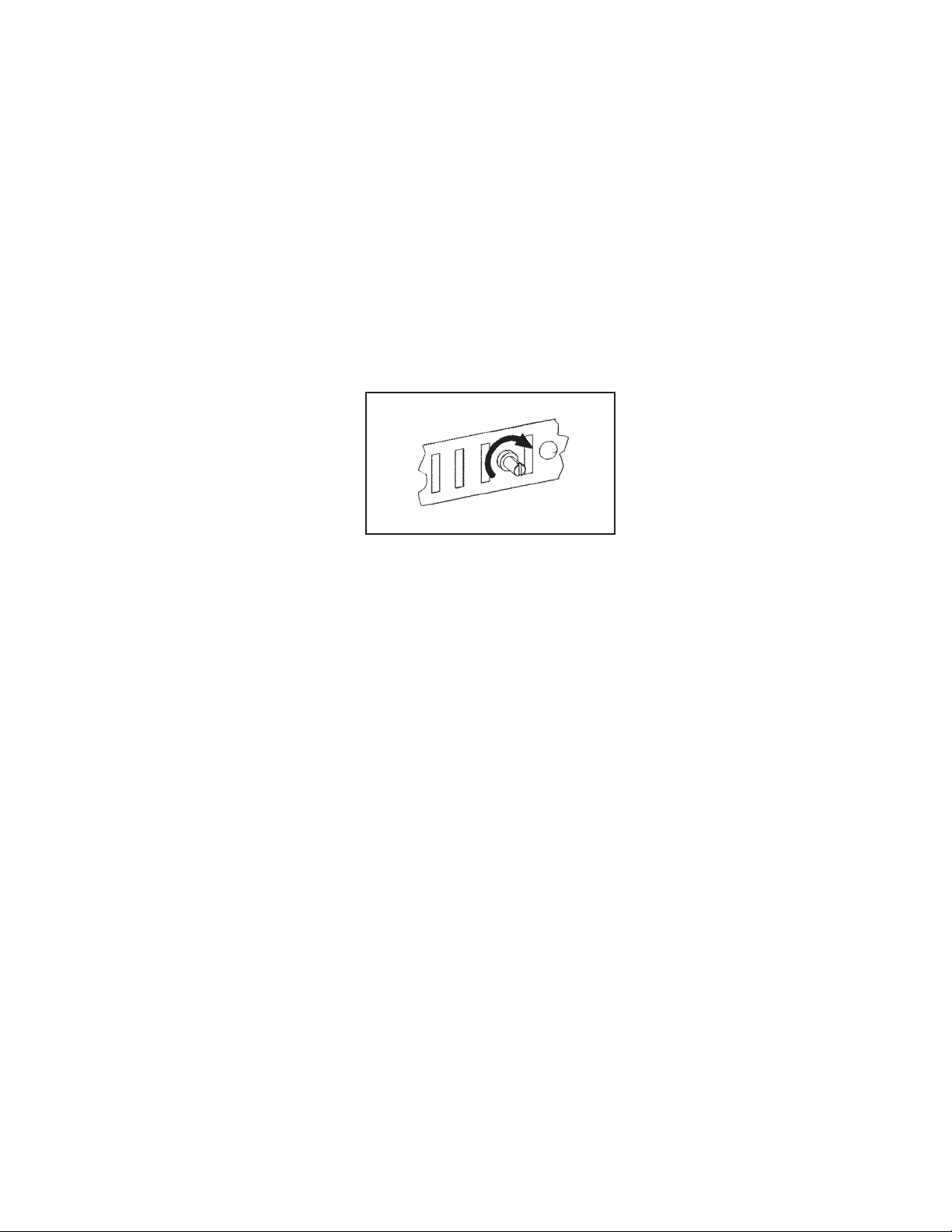
Temperature Range: 70 degrees to 120 degrees F (21 degrees to 49 degrees C). The adjustment turns 180
degrees. Three degrees of turn is approximately equal to one degree F of temperature
change. We suggest that you find the 180 degree range and set the switch at about the
halfway point. Then adjust as necessary to find the appropriate brooding temperature.
Turning the adjustment knob to the right (clockwise) increases temperature. See Exhibit C.
BROODER OPERATING INSTRUCTIONS
Plug brooder cord into 110-220 volt A.C. circuit. Adjust thermostat as discussed above.
Start at 95 degrees F (35 degrees C) 1 inch above floor at a point in center of brooder chamber. Reduce heat by 5 degrees
each week until chicks are transferred to finishing battery or grow-out pen.
Fill feeder full with no more feed than necessary to keep feed fresh daily. Always keep clean, fresh water for the chicks.
Drop pan should be cleaned daily. To facilitate cleaning pans, cover them each time with newspaper or litter to absorb
odors. Your water trough is self cleaning but you may want to periodically disinfect trough. Disinfect entire brooder each
time chicks are transferred to aid disease control.
Keep temperatures of the brooder room above 60 degrees F (16 degrees C) and provide ample ventilation without drafts.
PLEASE NOTE: In event of insufficient heat, call your power company and have them check the line voltage. A drop of ten
volts will result in the loss of more than 20% of the heating power of your heater. Our experience shows that in most cases of
low voltage, the line leading into the brooder house is too light and needs to be of heavier gauge. The greater the distance,
from the meter to brooder, the larger the wires should be. Consult your power company for correct wire gauges to insure full
voltage of 110-115 volts reaching the brooder.
WHILE CLEANING, DISCONNECT POWER SOURCE AND REMOVE HEATER ASSEMBLY.
GROW-OUT OPERATING INSTRUCTIONS
Our grow-out is designed for about 20-25 birds after brooding. For larger birds, you may want to consider Brower Model
4200, which has about 14 inches of headroom. Keep feed fresh by adding to the feed trough about the amount of feed that
can be consumed in a day.
Always keep clean, fresh water for the chicks. Drop pan should be cleaned daily. To facilitate cleaning pans, cover them
each time with newspaper or litter to absorb odors. Your water trough is self cleaning but you may want to periodically
disinfect trough. Disinfect entire brooder each time chicks are transferred to aid disease control.
Keep temperatures of the brooder room above 60 degrees F (16 degrees C) and provide ample ventilation without drafts.
EXHIBIT C
Warmer–Turn Clockwise
This manual suits for next models
1
Table of contents
Popular Farm Equipment manuals by other brands

Farmet
Farmet KOMPAKTOMAT K500PS operating manual

Wintex Agro
Wintex Agro 1000S instruction manual

Foster
Foster Cherry Products Super Scrubber GG1700X manual

Art's-Way Manufacturing
Art's-Way Manufacturing 6812D Operator's manual

KIFCO
KIFCO Water-Reel B140G Operator's manual

Gaspardo
Gaspardo G19502451 Use and maintenance