BRP Sea-Doo 295 100 457 User manual

Retractable Ski Pylon (Sea-Doo) (Kit P/N 295 100 457)
The following symbols may be used in this document:
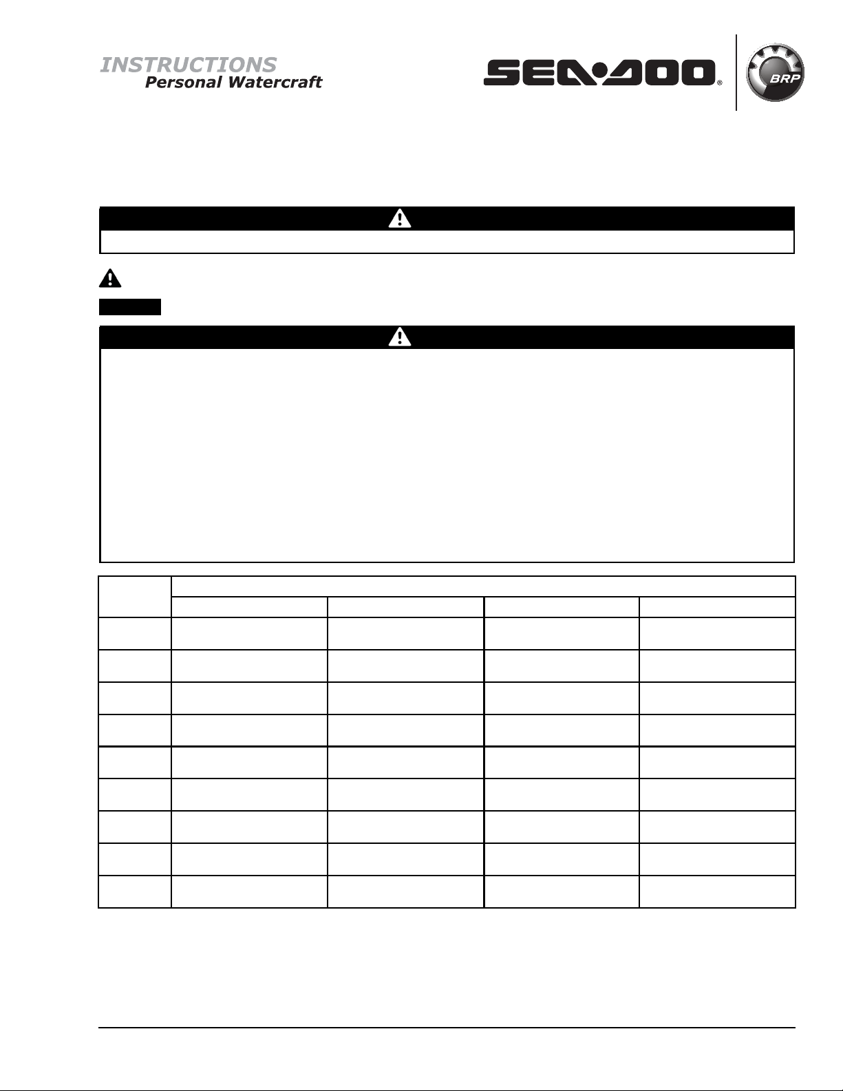
WARNING
Indicates a hazardous situation which, if not avoided, could result in death or serious injury.
CAUTION Indicates a hazard situation which, if not avoided, could result in minor or moderate injury.
NOTICE Indicates an instruction which, if not followed, could severely damage vehicle components or other property.
WARNING
– For safety reasons, this kit must be installed by an authorized BRP dealer.
– This kit is designed for specific applicable models only (authorized BRP dealers will confirm model(s)). It is not rec-
ommended for units other than the one (those) for which it was sold.
– This instruction sheet MUST be given to the purchaser.
– Should removal of a locking device (e.g. lock tabs, self-locking fasteners, etc.) be required when undergoing dis-
assembly/assembly, always replace with a new one.
– Torque wrench tightening specifications must strictly be adhered to.
– Always wear EYE PROTECTION AND APPROPRIATE GLOVES when using power tools.
– Unless otherwise specified, engine must be OFF when performing any operation on the vehicle.
– Always be aware of parts that can move, such as wheels, transmission components, etc.
– Some components may be HOT. Always wait for engine to cool down before performing work.
TORQUE TO BE USED WHEN TORQUES ARE NOT SPECIFIED IN TEXT
FASTENER
SIZE 5.8 GRADE 8.8 GRADE 10.9 GRADE 12.9 GRADE
M4 1.8±0.2N•m
(16±2lbf•in)
2.8±0.2N•m
(25±2lbf•in)
3.8 ± 0.2 N•m
(34±2lbf•in)
4.5±0.5N•m
(40±4lbf•in)
M5 3.3±0.2N•m
(29±2lbf•in)
5.0±0.5N•m
(44±4lbf•in)
7.8 ± 0.7 N•m
(69±6lbf•in)
9.0±1.0N•m
(80±9lbf•in)
M6 7.5±1.0N•m
(66±9lbf•in)
10.0 ± 2.0 N•m
(89 ± 18 lbf•in)
12.8 ± 2.2 N•m
(113 ± 19 lbf•in)
16.0 ± 2.0 N•m
(142 ± 18 lbf•in)
M8 15.3 ± 1.7 N•m
(135 ± 15 lbf•in)
24.5 ± 3.5 N•m
(18±3lbf•ft)
31.5 ± 3.5 N•m
(23±3lbf•ft)
40.0 ± 5.0 N•m
(30±4lbf•ft)
M10 29 ± 3 N•m
(21±2lbf•ft)
48 ± 6 N•m
(35±4lbf•ft)
61 ± 9 N•m
(45±7lbf•ft)
73 ± 7 N•m
(54±5lbf•ft)
M12 52 ± 6 N•m
(38±4lbf•ft)
85 ± 10 N•m
(63±7lbf•ft)
105 ± 15 N•m
(77 ± 11 lbf•ft)
128 ± 17 N•m
(94 ± 13 lbf•ft)
M14 85 ± 10 N•m
(63±7lbf•ft)
135 ± 15 N•m
(100 ± 11 lbf•ft)
170 ± 20 N•m
(125 ± 15 lbf•ft)
200 ± 25 N•m
(148 ± 18 lbf•ft)
M16 126 ± 14 N•m
(93 ± 10 lbf•ft)
205 ± 25 N•m
(151 ± 18 lbf•ft)
255 ± 30 N•m
(188 ± 22 lbf•ft)
305 ± 35 N•m
(225 ± 26 lbf•ft)
M18 170 ± 20 N•m
(125 ± 15 lbf•ft)
273 ± 32 N•m
(201 ± 24 lbf•ft)
330 ± 25 N•m
(243 ± 18 lbf•ft)
413 ± 47 N•m
(305 ± 35 lbf•ft)
NOTE: The illustrations in this document show typical construction of the different assemblies and may
not reproduce the full detail or exact shape of the parts; however, they represent parts that have the
same or similar function.
NOTE: Installation time is approximately 1.0 hour.
Printed in Canada. (ssi2011-030 en JT)
©2010 Bombardier Recreational Products Inc. and BRP US Inc. All rights reserved. Instruction Sheet P/N 487 800 755 1/11
®™ and the BRP logo are trademarks of Bombardier Recreational Products Inc. or its affiliates.

PARTS TO BE INSTALLED
ssi2009-001-001_a
ITEM P/N DESCRIPTION QTY
P1 291 002 995 Handle (ski pylon) 1
P2 291 002 553 Support 1
P3 291 002 712 Lateral Arm (RH) 1
P4 291 002 711 Lateral Arm (LH) 1
P5 230 060 060 M6 x 100
Hexagonal Bolt 1
P6 232 561 200 M6 Elastic Stop Nut 5
P7 234 062 600 M6 Flat Washer 2
P8 293 050 001 Flat Washer 2
P9 293 830 037 Rubber Washer 2
P10 205 484 060 M8 x 40 Rounded
Head Bolt 6
P11 232 581 200 M8 Elastic Stop Nut 8
P12 234 081 600 M8 Stainless
Flat Washer 6
P13 250 200 011 M8 Stainless
Flat Washer 2
P14 269 501 166 Nut Housing 4
P15 219 902 983 BRP Logo Decal 1
† 219 903 138 Warning label (French) 1
INSTRUCTIONS
Preparation
1. Remove or lift seat.
Up to 2009
2. Remove side bolts from both sides of grab han-
dle; keep bolts and flat washers for reuse.
1
F18P03A
1. Grab handle side bolts
NOTE: Lift coolant reservoir out of its bracket and
set it aside in order to ease removal of right for-
ward bolt.
3. Remove two M8 x 45 hexagonal bolts that are
retaining grab handle at rear center; discard
their elastic stop nuts but keep inside and out-
side flat washers with bolts for reuse.
4. Remove grab handle and set aside.
F18P04A
1
1. Grab handle center screws M8 x 45
5. Cut locking tie around upper exhaust hose (ex-
cept on RXT™-X™ models).
6. With a bungee cord, pull and secure hose for-
ward; this will provide more working space.
7. For vehicle with bailer hoses secured to
U-Clamp retainer plate, cut locking tie to un-
hook and set bailer hoses aside.
2 / 11 Instruction Sheet P/N 487 800 755

INSTRUCTIONS
1
F18P05A
HOSES SECURED WITH LOCKING TIES
1. Locking tie around bailer hoses
NOTICE Locking tie is secured onto the 90°
fittings. It is the way to secure bailer hoses
once wake pylon installation is completed.
2010 and up GTX and RXT platforms
8. Remove grab handle and bridge bolts from
body (8 x M6 bolts: 6 on sides and 2 at rear):
8.1 Remove the 4 bridge bolts.
8.2 Remove grab handle rear bolts.
ssi2010-005-001_a
TYPICAL - RXP SHOWN
1. Bridge bolt
2. Grab handle bolt
3. Grab handle
8.3 Remove bridge with coolant reservoir and
setitaside.
8.4 Remove and discard stop nuts and nut
housings. Keep flat washers for reuse.
ssi2010-005-002_a
1. Nut housing mounted in bridge
8.5 Remove remaining (2) grab handle bolts.
ssi2010-005-003_a
1. Grab handle
2. Handle bolt removal
2011 and up GTI and GTS platforms
9. Remove grab handle and coolant bottle
9.1 Remove the 6 retaining bolts. Keep flat
washers for reuse.
ssi2011-030-002_a
TYPICAL - GTI OR GTS SHOWN
1. Retaining bolts to remove
2. Coolant bottle
9.2 Remove and discard stop nuts and nut
housings in coolant bottle support.
All models
10. Remove and discard U-clamp, exterior finish
plate and nuts.
Instruction Sheet P/N 487 800 755 3 / 11

INSTRUCTIONS
NOTE: Keep retainer plate inside (already trapped
in silicone) or flat washers, depending on vehicle.
Replacement parts are supplied with the new kit.
F18P06A
2 3
1
U-CLAMP HOOK ASSEMBLY
1. U-Clamp
2. Hook
3. Finish plate
Drilling and Assembling
NOTICE Proper understanding of the follow-
ing steps is of the utmost importance. Make
sure the instructions are understood before
starting to drill holes in the deck.
2010 and up - Applicable models
1. Remove decal.
ssi2010-005-004
NOTE: Use the correct template for your water-
craft. Model names are indicated on template.
2. Precut and center hole template (attached to
the instructions) in circular flat recess on deck
(previous decal location) using tape.
NOTE: Make sure to orient template correctly ac-
cording to reference lines. Vertical line must be
aligned with length of vehicle, upside pointing to-
wards bow.
ssi2010-005-005
HOLE TEMPLATE IN POSITION - GTX - RXT MODEL SHOWN
ssi2011-030-001_a
HOLE TEMPLATE IN POSITION - GTI AND GTS MODEL SHOWN
3. Punch target mark.
ssi2010-005-006
Up to 2009
4. Using a square set at 61.6 mm (2-13/32 in), start
at center between both U-clamp holes (respect
the angle of the body) and project the most cen-
ter position on the rear hull.
4 / 11 Instruction Sheet P/N 487 800 755

INSTRUCTIONS
F18P0HA
3
3 1
2
A
USING SQUARE FOR MAST HOLE LOCATION
1. Distance from surface = 61.6 mm (2-13/32 in)
2. Most center position on rear hull
3. Square laid flat to the angle of body
A. 90° angle
5. Mark that spot with a marker pen. Punch it as
a guide for drilling operation.
All models
6. Place a piece of wood under drilling location to
protect internal components if necessary.
ssi2009-001-002
PIECE OF WOOD USED AS PROTECTOR
7. Using a 4.7 mm (3/16 in) bit, gently drill a hole in
hull.
NOTICE Take care not to press too hard to
start so bit will not skid off position, thus dam-
aging paint surface. Do not drill too deeply,
this could damage the intercooler or other
components.
F18P09A
8. Using a 57 mm (2-1/4 in) hole saw gently start
piercing the hull in a vertical alignment. Saw
will bite at front first; slowly keep on drilling in
that vertical alignment until saw goes through
body lining.
NOTICE The pilot drill bit should not extend
too far out of the hole saw. When performing
this step, be careful not to drill in components
located right under this location.
F18P0AB
A
1
2
USING HOLE SAW FOR PYLON MAST OPENING
1. Vertical alignment
2. Hole saw parallel with bumper line
A. 90° angle
9. Clean outside and inside hull from fiberglass
residues.
Instruction Sheet P/N 487 800 755 5 / 11

INSTRUCTIONS
ssi2009-001-003
10. Insert pylon support lower end through hole.
ssi2009-001-004_a
1. Pylon support [P2] installed to its location
11. Lean support upper section against body and
align with U-clamp/hook holes.
12. Insert M8 x 40 screw and flat washer to the
support upper section.
13. Assemble stop nut on backside and fasten
manually against the retainer plate or wash-
ers.
1
2
3
4
5
6
ssi2009-001-018_a
UPPER SECTION ASSEMBLY
1. M8 x 40 screw [P10]
2. Flat washer [P8]
3. Support [P2]upper section
4. Body lining (fiberglass)
5. Retainer plate or kept flat washers
6. Stop nut [P11]
14. Tighten stop nut to 11.5 N•m ± .5 N•m
(102 lbf•in ±4lbf•in).
15. Drill 8 mm (5/16 in) holes through body lining
by using lower section holes as templates (not
shown).
16. Remove the piece of wood protecting the in-
ternal components.
17. Insert M8 x 40 screw with flat washer to the
support lower section holes.
18. Assemble rubber washer, steel flat washer
and stop nut on the backside and fasten man-
ually against body lining.
1
2
3
4
5
76
ssi2009-001-019_a
LOWER SECTION ASSEMBLY
1. M8 x 40 screw [P10]
2. Flat washer [P12]
3. Support [P2]lower section
4. Body lining (fiberglass)
5. Rubber washer [P9]
6. Steel flat washer [P13]
7. Stop nut [P11]
19. Tighten nuts to 11.5 N•m ± .5 N•m
(102 lbf•in ±4lbf•in).
ssi2009-001-006_a
ASSEMBLING SUPPORT LOWER SECTION
1. Rubber washer [P9]
2. Steelflatwasher[P13]
3. Nut [P11]
6 / 11 Instruction Sheet P/N 487 800 755

INSTRUCTIONS
ssi2009-001-007
20. Locate side and position of lateral arms (LH &
RH) on the support.
NOTE: RH & LH parts names are indicated on the
backside.
ssi2009-001-008
SEE LH/RH INDICATION ON BACKSIDES
NOTE: For GTI and GTS models, invert RH and LH
side for installation.
ssi2011-030-003_a
SKI PYLON INSTALLATION ON GTI AND GTS
1. RH arm installed on LH side
2. LH arm installed on RH side
21. Assemble M6 x 100 bolt through the ski pylon
support with M6 flat washers and nut.
ssi2009-001-009_a
TYPICAL
1. Ski pylon support [P2]
2. RH arm [P3]
3. LH arm [P4]
4. M6 x 100 bolt [P5]
5. M6 flat washer on both sides [P7]
6. M6 nut [P6]
22. Tighten M6 x 100 bolt to 8 N•m ± 1 N•m
(71 lbf•in ±9lbf•in).
Up to 2009
23. Using a square, trace gauge line for drilling.
ssi2009-001-010_a
1. RH arm [P3]
A. Distance from surface to drilling gauge line = 35 mm (1-3/8 in)
B. Surface reference plane
C. Gauge line trace
2010 and up GTX and RXT platforms
24. Using a square, trace a line for drilling.
Instruction Sheet P/N 487 800 755 7 / 11

INSTRUCTIONS
ssi2010-005-007_a
A. Distance from surface to drilling gauge line = 52 mm (2 in)
B. Reference plane surface
C. Gaugelinetrace
All models
25. Rotate/bring arm to its position aligning the
center of its hole with the gauge line or cen-
tering it vertically in its recess for GTI/GTS plat-
forms.
ssi2011-030-004_a
SKI PYLON ARM INSTALLATION - GTI-GTS SHOWN - TYPICAL
1. Recess
2. Ski Pylon arm centered vertically
NOTE: Make sure that arm is correctly oriented
and that its surface matches that of the hull.
26. Drill a 8 mm (5/16 in) hole through body lining
by using arm screw hole as a template.
NOTICE Respect arm screw hole angle dur-
ing drilling for a better assembling. Hold part
firmly.
ssi2009-001-011_a
1. 8 mm (5/16 in)drill bit
A. Holding part in position
27. Insert a M8 x 40 screw [P10]with a flat
washer [P12]through both arm holes.
28. Assemble a flat washer [P12]and a stop nut
[P11]on the backside and fasten manually
against body lining.
29. Tighten arm screws to 11.5 N•m ± 1.5 N•m
(102 lbf•in ±13lbf•in).
Reinstallation and Final
Assembly
Up to 2009
1. Remove bungee cord so upper exhaust hose
sets to its position and secure upper exhaust
hose with a locking tie.
2. Reinstall grab handle using new nut housings
[P14], nuts and the kept M6 bolts on both sides.
3. Tighten to 8 N•m ± 1 N•m
(71 lbf•in ±9lbf•in).
ssi2009-001-012
4. Secure grab handle at rear using kept M8 x 45
hexagonal bolts and flat washers with new M8
elastic stop nuts [P11].
5. Tighten nuts to 8 N•m ± 1 N•m
(71 lbf•in ±9lbf•in).
8 / 11 Instruction Sheet P/N 487 800 755

INSTRUCTIONS
2010 and up GTX and RXT platforms
6. Reinstall grab handle using new nut housings
[P14], nuts [P6], and the kept M6 bolts and
washers on both sides and rear.
7. Tighten to 8 N•m ± 1 N•m
(71 lbf•in ±9lbf•in).
ssi2010-005-003_b
1. Grab handle
2. Handle bolt installation
8. Reinstall bridge with coolant reservoir using the
4 bridge bolts and new M6 nut housings [P14].
ssi2010-005-001_b
1. Grab handle
2. Grab handle (rear) bolt
3. Bridge retaining bolt
9. Tighten nuts [P6] to 8 N•m ± 1 N•m
(71 lbf•in ±9lbf•in).
2011 and up - GTI and GTS platforms
10. Reinstall grab handle and coolant bottle sup-
port using new nut housings [P14], nuts [P6]
and the kept M6 bolts and washers on both
sides.
11. Tighten to 8 N•m ± 1 N•m
(71 lbf•in ±9lbf•in).
All models
12. If you moved bailer hoses, secure them back
in place with a new locking tie.
NOTICE Remember to align locking tie onto
90° fitting and not on hoses.
1
F18P05A
HOSES SECURED WITH LOCKING TIES
1. Locking tie around bailer hoses
13. Insert the pylon cylinder into the support.
ssi2009-001-013_a
1. Pylon handle [P1]
2. Pylon cylinder notch for safety lock
14. Make sure cylinder slides up and down freely
without obstruction from grab handle then re-
sume the procedure.
WARNING
Make sure the safety mechanism stops the
cylinder in its up position.
Instruction Sheet P/N 487 800 755 9 / 11

INSTRUCTIONS
ssi2009-001-014
CHECKING PYLON HANDLE MOVEMENT
Pylon cylinder may be unlocked and removed
from its support by pressing the support collar.
ssi2009-001-015_a
A. Pushing down collar to unlock cylinder
15. Reinstall coolant reservoir into its brackets.
16. Reinstall seat.
17. Apply BRP decal to its location.
ssi2009-001-016
WARNING
Completely retract ski pylon when not used.
Do not hold rear grab handle while retract-
ing ski pylon. Make sure it is fully extended
and locked before use. Spotter must always
keep hands on ski pylon handle while pulling
a skier or a wakeboarder.
WARNING LABEL
This product comes with the following, already ap-
posed, english warning label containing important
safety information. Install the french label if nec-
essary.
219903137
ENGLISH LABEL (P/N 219 903 137)
219903138
FRENCH LABEL (P/N 219 903 138)
The label should be considered permanent part of
this product. If the label comes off or becomes
hard to read, please contact an authorized dealer
for replacement.
Any person who intends to use this product
should read and understand the information con-
tained on the warning label before doing so.
10 / 11 Instruction Sheet P/N 487 800 755

4 po/in
4 po/in
GTX, RXT GTI, GTS
UP/
HAUT
VERTICAL
HORIZONTAL
UP/
HAUT
VERTICAL
HORIZONTAL
Ensu e template is to scale/
Sassu e que le gaba it est à léchelle
100 mm
100 mm
295100457
Instruction Sheet P/N 487 800 755 11 / 11
Table of contents
Other BRP Boating Equipment manuals
Popular Boating Equipment manuals by other brands

Garmin
Garmin GPSmap 8500 GRID installation instructions

AWD
AWD AWD0907 instruction manual

Ultraflex
Ultraflex ZTF Tiller System installation manual

Selden
Selden CXe25 OD manual

Origin
Origin Catapult installation guide

Raritan
Raritan PURASAN EX Hold n' Treat Operation, maintenance, and installation instructions