Brubaker Models WildKard Parts list manual
Building the...
WildKard
brubakermodels.com
build it, fly it.

1
WARNING!
A model aircraft is not a toy and must be handled with respect and care. The following
warnings apply. Please read this entire page.
ŸThis aircraft may be capable of speeds in excess of 60 miles per hour. As such it is
capable of severe injury. This is not a “beginner” aircraft. If you are a student pilot please
get help from an experienced pilot or model club before flying this aircraft.
http://www.modelaircraft.org/ is a great place to start.
ŸThe spinning propeller can cause severe injury. Stay clear of it at all times. Do not allow
spectators to stand in the “arc” of the prop. Always treat an electric motor as “armed” if
you are unsure! Wear safety glasses and hearing protection as required. Keep loose
clothing and tools away. Do not start and run the engine over loose gravel or sand.
Carefully train your helper to hold the aircraft while starting, and navigate or carry it safely
to the flight line.
ŸLithium batteries can explode and cause intense fires. Read and understand the
instructions for your particular batteries. Handle them properly and use the correct
charger.
ŸFly the model at a designated field or other safe place. Do not fly over spectators or other
persons, private property, or buildings. Maintain a positive image of our hobby for all
concerned.
ŸWhile building, use safe shop procedures. Remember to provide adequate ventilation
while using any glues, finishes or other chemicals.
ŸUse common sense at all times and don't be afraid to ask for help from experienced
modelers or contact us at Brubaker Models.
Contact info:
email - [email protected]
phone - 661.557.0299
web - http://brubakermodels.com/
WARRANTY
Brubaker Models guarantees that this kit is free from defects in workmanship and
materials when purchased. This warranty will not cover any modified parts or damage
due to use. Brubaker Models liability shall not exceed the original purchase price of the
kit under any conditions. The quality, safety, and performance of the completed model
depends entirely upon the builder. No guarantee to the safety or performance of this
model is expressed or implied. Brubaker Models has no control over the construction of
this product and as such, assumes no liability for damage or injury resulting from its use.
The builder assumes all liability by assembling and using this product. If the builder does
not wish to assume this liability, he/she is advised to return the kit in new and resalable
condition to Brubaker Models.
All content © 2015 BRUBAKER MODELS

2
INTRODUCTION
Thank you for purchasing a Brubaker kit! There are many choices
in the model aircraft market. My commitment is to make sure that
you end up with an aircraft that you are proud to own and love to
fly. This is a KIT. Yes, it will require thought and craftsmanship to
build. I have made every effort to work out the “kinks” during the
design process. I will do my level best to support you should any
questions arise during the build. Parts are available. I also value
your suggestions. Please contact me should you need assistance
or have feedback on the model.
Contact info:
email - [email protected]
phone - 661.557.0299
web - http://brubakermodels.com/
facebook - https://www.facebook.com/brubakermodels

3
The Contents of this Kit:
Ÿ3 Laser Cut Foamboard Sheets
(fuselage, right wing, left wing)
ŸPosterboard Parts Sheet
ŸLite ply Motor Mount
ŸBirch ply Control Horns
ŸElevator Joiner Wire
ŸHardware for 3 Pushrods
ŸVelcro
ŸMotor Mounting Screws w/Nutplates
Aircraft Specs:
Wingspan: 30”
Length: 30”
Weight: 18 - 22 oz.
4 Channel w/Mixing
Required Components (not included in kit):
ŸPark 400 and up Brushless Motor w/Speed Control
ŸProp and Prop Hub (Sized to fit Motor)
Ÿ3 Micro Servos (HiTec Hs55 or similar)
ŸLipo Battery Pack (800-1200 mah, 3-4 cell)
ŸTransmitter with Mixing Capability
ŸReceiver with at least 4 Channels
*Note: The laser cut motor mount is pre-drilled to fit either the Great Planes
Cross Mount for 28mm Rimfire Motors (Tower stock #LXVPC2) or the HobbyKing
Turnigy Park 450 mount. The bolting diameter is 1.310".

4
Getting Started
You will also need a few basic tools and supplies to build this kit.
They are as follows:
ŸHot Glue Gun w/
Glue Sticks
ŸHobby Knife or
Box Cutter
ŸPopsicle Sticks
ŸSanding Block w/
180 grit paper
ŸPliers / Wire
Cutters
Also helpful are a good
building board, some 3M
77 spray glue, and spray
paint.
Left Wing Sheet Right Wing Sheet
Fuselage Sheet
#1
#3 #2
Posterboard Parts
and Stencils
Motor Mount
Control Horns
Laser Cut Parts Diagram
*Drawings not to scale

5
WINGS
Getting started! You’ll need these parts:
Note tick marks
to align center
Leading Edge Score Line
Spar Score Lines
Trailing Edge Bevel Mark
Hinge Line
Hinge Bevel Mark
Winglet Folding
Channel
Control Horn Slot
SPAR
BOTTOM SKIN
TOP SKIN
WINGLET
AILERON
6
Begin by removing the pieces from
the foam board, using a hobby knife
to cut the connecting tabs when
necessary.
Starting with the right wing panel,
“break” open the score mark at the
leading edge. Do this over the edge
of your building board.
Leading Edge
Score
Press Down Here
Building Board
Edge
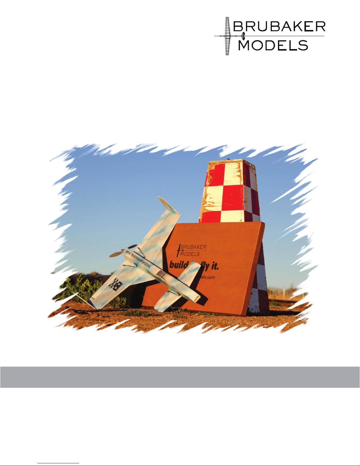
Fold the wing in half on the score
line and cut a 45° bevel on both
sides of the fold it opens up. Use a
sharp knife and be careful to not cut
through the paper in the center; it
will become your leading edge. You
can sand these bevels a bit with
your 180 block if desired.
45 Bevel both sides
of Leading Edge
Score
Wing is folded
open on the
Leading Edge
Score
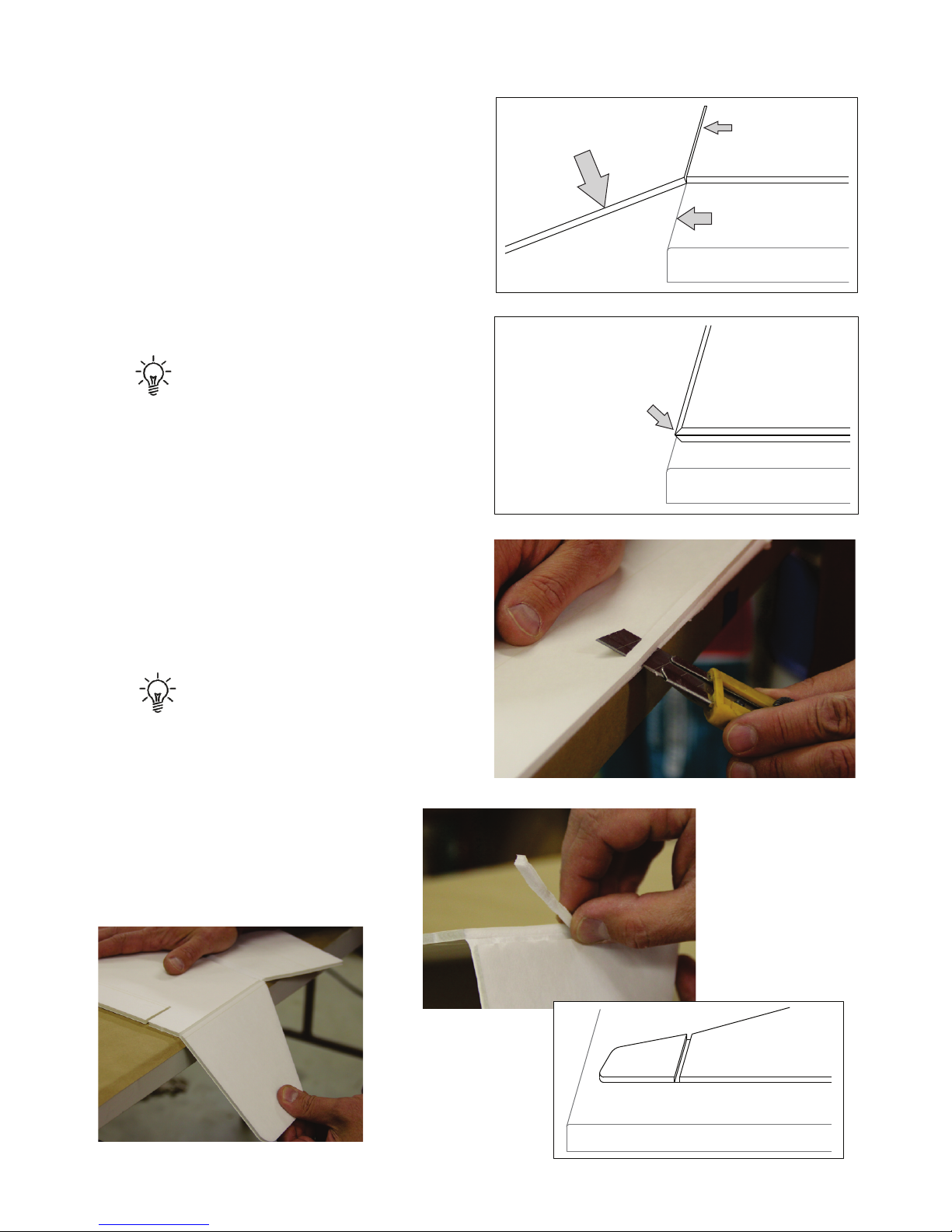
Break open the winglet along
both score lines and peel out
the strip of foam between
them to create a channel.
Winglet Channel
Cutting the bevel:
REMEMBER: SAVE THE
CENTER CONNECTING
PAPER!
THE DIAGRAM ON PAGE
5 WILL HELP IDENTIFY
SCORE LINES ETC.
7
Break open the aileron.
The connecting paper
will become the hinge.
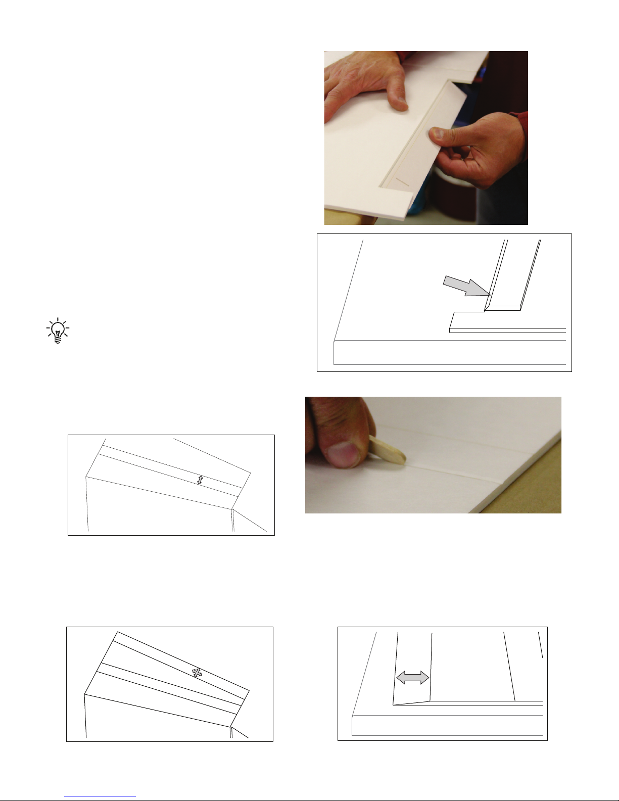
Using a popsicle stick, lightly
crease the two spar score lines.
Flip the wing over and fold the aileron
over onto the bottom surface. Cut a
45° bevel on the aileron using the
marking line provided. Sand the
bevel smooth if necessary.
Peel away the paper at the trailing edge of the top skin to the trailing edge bevel
mark. You may have to score the paper a bit if it isn’t cut through. Sand this area
to a knife edge bevel. Be careful not to sand through the paper on the
underneath side.
Aileron beveled to
45°
Crease here
Peel paper
away here
Trailing Edge
Score Line
Bevel
Spar Area
REMEMBER: SAVE THE HINGE
CONNECTING PAPER!

8
Now repeat the entire process for the left wing. When finished you will have 2
wing panels that look like this, ready for glue!
YOU WILL BE USING YOUR HOT
GLUE GUN FOR MOST OF THIS
BUILD. WHERE OTHER
ADHESIVES ARE UTILIZED IT
WILL BE NOTED.
Place the right wing panel on your
board and glue the spar in its
location as shown. You can draw a
pencil line between the tick marks
at the spars center if you wish.
Make sure it is correctly aligned on
the center and along the score line
closest to the leading edge fold.
Center
Aligned
Here
Align to Spar Score
Bead of Hot Glue
between Spar and
Top Skin
Correct Orentation
Press the glue down firmly:
KEEP YOUR GLUE GUN
LYING ON A SCRAP OF
CARDBOARD SO IT
DOESN’T DRIP HOT GLUE
ON THE BENCH
Gluing the Spar

9
*
Beads of hot glue in
these 4 locations
TOP SKIN/SPAR
FOLDS DOWN ONTO
BOTTOM SKIN
Without gluing fold the top
skin over onto the bottom
skin. Work it down gently,
back and forth, pressing from
front to back, forming the
airfoil.
The airfoil cross section looks
like this:
When you are satisfied
that it folds as it should,
put beads of glue in the 4
locations shown in the
diagram. Immediately
fold it over and press it
down in place as you did
above. Make sure the
spar is firmly seated and
continue to work the
trailing edge down as the
glue cools.
Folding the Right Wing
*Note that right and left are always designated as if you were in
the cockpit with the with the aircraft right side up.
Table of contents


