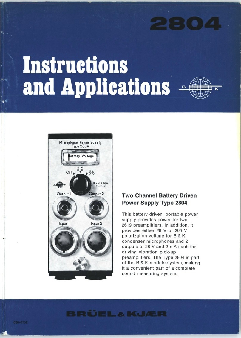
BRUEL & KJAER 2807 User guide

• •
Signal Adj. 1 lnput 2 Signal Adj.2
Input 1
Out:ut
1 Chopped
Output
1 • •
Ext
. Control
Input
1-
Output1 • Chopped
Input
2-0utput
Int. Control
•
Two
Channel •
Microphone
Power
Supply
Input 1 Type
2807
Input 2
Two Channel Microphone
Power Supply
Type 2807
The 2807 is a
compact
instrument
of
modular
construction
providing
stabilized voltages
for
8 & K
Microphone
Preamplifiers and
Condenser Microphones. The
low
output
impedance
of
its two amplifier
channels enables long cables to be
used
for
connection
of
indicating
instruments. The two channels may
be monitored simultaneously,
or
they
may be automatically
or
remotely
switched so they can
be
monitored
alternately using a
single
indicating instrument.


TWO
CHANNEL
MICROPHONE POWER SUPPLY
TYPE 2807
October 1971

CONTENTS
1.
INTRODUCTION
......................................
3
2.
CONTROLS
..........................................
4
2.1.
Front
Panel
..................................
4
2.2.
Rear
Panel
. . . . . . . . . . . . . . . . . . . . . . . . . . . . . . . . . . 7
2.3.
Bottom
Panel
. . . . . . . . . . . . . . . . . . . . . . . . • . . . . . . . 9
3. OPERATION
........................................
10
3.1. Preliminary Adjustments
.........
.
.........
.
..
10
Voltage Selector
................
.
............
10
Polarization Voltage
..........................
10
3.2. Connection
of
Measuring Instrumentation
.........
11
3.3.
Use
of
Ext.
Control
Socket
.....................
11
3.4. Installation in Module System
..................
12
4. DESCRIPTION
.......................................
14
4.1.
Amplifier
Channels 1
and
2
....................
14
4.2.
Automatic
Channel Selector
....................
18
4.3. Power Supply
..........
.
....................
18
5.
APPLICATIONS
......................................
20
5.1. Sound Insulation Measurements
.................
20
5.2.
Vibration
Measurements
.......................
22
5.3. Simultaneous Recording
of
Sound and
Vibration
Data
23
6.
SPECIFICATIONS
....................................
24

1.
INTRODUCTION
The
Two
Channel Microphone Power Supply Type 2807
is
a compact
instrument
of
modular construction designed
for
use
with
the B & K Micro-
phone Preamplifiers Type 2615, 2618, 2619 and 2627.
It
supplies stabilized
voltages
to
po'N'er
the
preamplifiers and accompanying condenser micro-
phones and
has
two
amplifier
channels
to
convert the
output
impedance
of
the preamplifiers
to
a
low
impedance
so
that
long cables may
be
used
to
connect recording
or
measuring instrumentation. The amplifiers
have
a
linear frequency response which
is
flat
to
within
±0.2 dB
from
2 Hz
to
200kHz
and have a gain
of
approximately
unity.
A separate
multi-turn
potentiometer at the
input
of
each
amplifier enables
input
signals
to
be
attenuated
by
more than
40
dB. The cross-talk between the
two
amplifiers
is
better than
-60
dB.
The
two
channels
of
the 2807 may either be
used
independently
of
one
another,
or
they may be automatically or remotely switched enabling the
output
of
both
channels
to
be monitored using one
set
of
recording
or
measuring instrumentation.
Automatic
switching
is
accomplished using a
relay operated
by
an
internal
multivibrator.
The switching frequency
is
approximately 2 Hz. For remote switching
the
relay
can
be operated
by
grounding
an
EXT.
CONTROL
using either
an
external switch,
or
the two-
channel selector
of
the 2305 Level Recorder. The advantage
of
using the
Level Recorder
for
this purpose
is
that
the
output
from
both
channels can
be recorded simultaneously on frequency calibrated paper.
The 2807 may also be employed
as
an
impedance converter
for
vibration
measurements.
For
this
purpose the 2807 can be used together
with
the
Vibration
Preamplifier Type
2623
and the Power Supply
ZR
0024 or
with
the high
input
impedance Microphone Preamplifiers
Type
2615, 2619, and
2627.
3

2.1. FRONT PANEL
Input
INPUTS 1
and
2:
4
2.
CONTROLS
Input
2
Fig.2.1.
Front
Panel
of
2807
Two
7
pin
sockets
for
connection
of
B & K
Condenser
Microphones
or
Accelerometers,
via
their
associated preamplifiers
to
the
inputs
of
channel 1
and
2 amplifiers respectively.
The
sockets
also carry
the
necessary
supply

Anode Voltage
+ 130 V (2 rnA)
Heater Voltage
+ 12.6 V (100 rnA)
Heater Voltage
+6.3 V (200 rnA)
and polarization voltages
for
powering the
preamplifiers and microphones which
are
con-
nected. The internal connections
to
the
sockets
are
shown in Fig.2.2.
Signal
Input
Ground
Polarization
-+--Voltage
+200 V (10
p.A)
Ground
IT/29.3
Fig.2.2. External view
of
the sockets
INPUT
1and 2
SIGNAL
ADJ. 1 and 2:
FUNCTION
SELECTOR:
Multi-turn
potentiometers
for
adjustment
of
the
input
signals applied at sockets
INPUT
1
and 2 respectively. The
range
of
attenuation
is
from
0
to
40
dB.
Five position switch
with
the
following
func-
tions:
"Input
1 -
Output
1.
Input
2 -
Output
2".
The
input
and
output
of
channel 1 amplifier
are
connected
to
the respective sockets IN-
PUT 1 and
OUTPUT
1.
Similarly the
input
and
output
of
channel 2
amplifier
are
con-
nected
to
the respective sockets INPUT 2 and
OUTPUT
2.
"Input
1 -
Output
1
".
The
input
and
output
of
channel 1
amplifier
are
connected
to
the
respective sockets
INPUT
1 and OUTPUT
1.
The sockets OUTPUT 2
are
grounded.
5

INDICATORS 1
and
2:
OUTPUTS 1
and
2:
CHASSIS GROUND:
6
"Input
2-
Output
1".
The
input
and
output
of
channel 2
amp
Iifier are
connected
to
the
respective sockets INPUT 2
and
OUTPUT 1.
The
sockets OUTPUT 2 are grounded.
"Chopped
Ext.
Control".
The
outputs
of
channel 1 and 2 amplifiers
may
either
be
chopped
using
the
2305
Level
Recorder
con-
nected
to
the
EXT.
CONTROL
socket,
or
they
may
be selected by grounding
the
socket.
The
chopped
or
selected
outputs
are available
at
the
sockets OUTPUT 1.
The
sockets
OUT-
PUT 2 are grounded.
"Chopped
Int.
Control".
The
outputs
of
chan-
nel 1 and 2 amplifiers are
chopped
at
a fre-
quency
of
approximately
2 Hz
by
a relay
operated
from an internal multivibrator.
The
chopped
signal
is
available at
the
socket
OUT-
PUT 1.
The
sockets OUTPUT 2 are grounded.
Two
neon indicator
tubes
which
when
lit
signify
that
either
or
both
of channel 1 and 2
amplifiers are functioning.
Two
standard
B & K coaxial
sockets
which
depending
on
the
setting
of
the
FUNCTION
SELECTOR,
are
connected
to
the
outputs
of
channel 1 and 2 amplifiers.
The
sockets
accept
the
B & K Plugs
Type
JP
01
01 and are con-
nected
in
parallel
to
the
sockets
of
the
same
name
on
the
rear panel of
the
2807.
The
out-
put
impedance
is
13 n
in
series with 4.7
JJ.F.
Socket
for
connection
the
chassis
of
the
2807
to
ground.
The
socket accepts
the
B & K
Banana Plugs
Type
JB
0002/3.

2.2. REAR PANEL
Pol.
Volta
POL. VOLTAGE:
Ext.
Control
Output
1
Power
Switch
Fig.2.3, Rear Panel
of
2807
Socket
for measurement
of
the
polarization
voltage using an external
DC
digital voltmeter
having a rating of
at
least
20
kil/volt.
A
CHASSIS GROUND
socket
which may
be
used
as
a
DC
return when measuring
the
polarization voltage
is
situated immediately
to
the
right of
the
POL. VOLTAGE socket.
To
adjust
the
polarization voltage see section 3.1.
7

EXT. CONTROL:
OUTPUTS 1 and
2:
POWER:
MAINS INPUT:
Transformer
Shield
Socket
which
when
grounded operates an
internal relay
to
connect
the
sockets
OUTPUT
1 from
the
output
of
channel 1
to
the
output
of
channel 2 amplifier when
the
FUNCTION
SELECTOR
is
set
to
"Chopped
Ext. Con-
trol".
The
socket
may also be used
in
conjunc-
tion
with
the
Two-Channel Selector of
the
2305
Level Recorder which will remotely
chop
the
outputs
of
the
two
amp
Iifier chan-
nels.
The
socket
accepts
the
Banana Plugs
Type
JB
0002/3.
For
further
information see
section 3.3.
Two
miniature coaxial sockets which are con-
nected
in
parallel
to
the
sockets
of
the
same
name on
the
front
panel. Depending on
the
setting
of
the
FUNCTION SELECTOR,
the
sockets are
connected
to
the
outputs
of
chan-
nel 1 and 2 amplifiers which have an
output
impedance
of
13 Q
in
series with
4.7
pF.
The
sockets
accept
the
8 & K Miniature Coaxial
Cables
type
AO
0037,
AO
0038,
AO
0051,
AO
0052,
or
AO
0500.
On/Off
switch for power.
For
connection
of AC mains supply with
provision
for
connecting
one
of
the
mains
transformer
shields
to
the
earth
of
the
mains
supply.
For
connections
see Fig.2.4.
AC
Supply
170509
Fig.2.4.
MAINS
INPUT
socket
of
2807
8

2.3. BOTTOM PANEL
,,
,,
, ® ®
' a
~·
0
""
.
!· J
0 -
l
,.
l ,.
;
,,1
® ®
Voltage Selector
Fig.2.5. Bottom Panel
of
2807
VOLTAGE SELECTOR: For selection of
the
correct
mains voltage.
The selector may be
turned
to
the correct
voltage using a small coin, or wide blade
screwdriver, when
the
knob in
the
centre
of
the
selector
is
unscrewed. The knob contains a
250
rnA
mains fuse.
9

3.
OPERATION
3.1. ADJUSTMENTS
3.1.1. Voltage Selector
Before
the
instrument
is
used check
that
the
VOLTAGE SELECTOR
(see Fig.2.5)
on
the
bottom
panel of the 2807
is
set
to
the
correct
mains
voltage. If not, unscrew
the
knob
at
the
centre of
the
selector and
turn
the
selector
to
the
correct voltage indication using a small coin, or wide blade
screwdriver.
3.1.2. Polarization Voltage
The
200
Volt polarization voltage provided by
the
2807 for condenser
microphones
is
preset at
the
factory
to
within ±1 Volt and therefore
further adjustment
is
not
normally necessary. If it
is
required
to
check, or
adjust it however,
then
it should be measured using a digital voltmeter
(meter rating
20
kil/Volt)
connected between
the
POL. VOLTAGE and
Fig.3.
1.
Polarization voltage adjustment
10
Polarization
Voltage
Adjustment

CHASSIS GROUND sockets
of
the
instrument.
The
polarization voltage
adjustment
potentiometer
is
situated
on
the
main
printed
board (see
Fig.3.1)
on
the
right
hand
side (as viewed from rear)
of
the
instrument. It
is
accessible by unscrewing
the
right-hand panel fastening screw
on
the
rear
panel and sliding
the
panel
towards
the
rear
of
the
instrument.
3.2.
CONNECTION
OF
MEASURING INSTRUMENTATION
1.
Carry
out
the
preliminary
adjustments
necessary. See section
3.1~
2.
Connect
the
POWER INPUT
socket
to
the
mains supply using
the
mains cable supplied.
3.
To
one
or
both
of
the
sockets INPUT 1 and INPUT 2 fit
the
appro-
priate preamplifiers and
measurement
transducers.
For
sound meas-
urements
the
Microphone Preamplifiers
Type
2615,
2618,
2619
and
2627
are recommended. For vibration measurements see section 5.2.
4.
Set
the
FUNCTION SELECTOR switch
to
the
appropriate operating
mode.
5. Depending on
the
operating
mode
selected,
connect
one
or
both
of
the
sockets OUTPUT 1 and OUTPUT 2
to
the
recording and meas-
uring instrumentation.
The
effect
of
capacitive loading on
these
sockets
is
shown
in
Fig.4.2.
6. Switch
the
power on. Because
the
2807
is
transistorized no warm
up
time
is
necessary and it
is
therefore
ready for use immediately.
3.3. USE OF EXTERNAL CONTROL SOCKET
In
the
"Chopped
Ext.
Control"
mode
of
the
FUNCTION SELECTOR
switch
the
channel selector relay
of
the
2807
may be
operated
remotely by
grounding
the
EXT. CONTROL socket.
The
phasing
of
the
relay
is
such
that
when
the
socket
is
grounded
the
relay will switch from
the
output
of
channel 1
to
the
output
of
channel 2.
The
selected channel
output
is
applied
to
the
sockets OUTPUT 1, whilst
the
sockets OUTPUT 2 are grounded.
The channel selector relay may also be
operated
using
the
Two-Channel
Selector
of
the
2305
Level Recorder
to
ground
the
EXT. CONTROL socket.
The selector
is
a cam
operated
micro-switch which
is
mechanically
coupled
11

e~oe'
~
e
Mode in Oenrnoril
Ext. Control
Chassis Ground
Two-Channel
Selector Socket
of 2305
Level
Recorder
(External view)
77~390
Fig.3.2. External connections from the EXT. CONTROL and CHASSIS
GROUND sockets
of
the
2807
to the Two-Channel Selector
of
the
2305
Level Recorder
to
the
drive
shaft
mechanism
of
the
lever recorder.
Thus
by
selecting a
suitable drive
shaft
speed using
the
recorders DRIVE
SHAFT
SPEED con-
trol,
the
output
of
the
2807
may
be
chopped
at
a
frequency
which
permits
the
output
of
both
channels
to
be
recorded
alternately
using
one
chart
length
of
the
recording
paper
(see Fig.5.2).
The
connections
from
the
EXT.
CONTROL
socket
to
the
Two-Channel
Selector
of
the
2305
Level
Recorder
are shown
in
Fig.3.2.
3.4.
INSTALLATION
IN
MODULE
SYSTEM
The
2807
is
part
of
the
B & K
KK
Module
System.
The
system
is
designed
for
easy rack
mounting
of
instrument
combinations
so
that
entire
measurement
systems
may
be assembled
in
the
same rack.
Fig.3.3.
The
8 & K Module System
12

..
The system consists
of
a metal case
KK
0014
into
which
the
modules are
mounted.
For
mounting
the
case into a
19
inch rack, it can be fitted with
the
slotted
flanges GV
1037,
or if a
more
rugged
instrument
is
required
the
metal case
can
be fitted with
the
wooden
case
KA
0027
for protection.
For
further
information on
the
module system
consult
the
KA, KK, KO,
KS
Assembly Instructions.
13

4.
DESCRIPTION
The
principle
of
operation
of
the
2807
Two
Channel Power
Supply
will
be described with reference
to
the
schematic diagram given in Fig.4.1.
Preamplifier Signal
Input
1 Signal Channel 1
Output
Input
1 @
Adj.
1
Ampljfier
1
/
/
/
/
/
Ext
. switch
Automatic
/
Channel /
Control
Selector /
Supply
Pol.
Voltages 0 0
Internal
Switch
Control
""' ' ' '
Preamplifier @ Signal
Amplifier
' '
Output
Input 2
Adj
. 2 Channel 2 2
Signal
Input
2
~-
1
66
109
Fig.4.
1.
Schematic diagram
of
the
2807
4.1. AMPLIFIER CHANNELS 1 AND 2
The sockets INPUT 1
and
INPUT 2
accept
the
7 pin plugs of
the
B & K
Microphone Preamplifiers
Type
2615,
2618,
2619
and
2627.
Pin 4 (see
Fig.2.2)
of
the
sockets
is
the
respective
input
to
the
two
amplifier channels
of
the
2807,
whilst
the
remaining pins
supply
stabilized voltages from
the
2807
to
operate
the
preamplifiers and
condenser
microphones.
The
two
amplifier channels are 3 stage class
A-
B,
push-pull transistor
amplifiers with a voltage gain
of
approximately
unity
(i.e.
<0.15
dB
atten-
uation). Each has a multi-turn
potentiometer
at
its
input
for separate
atten-
uation
of
signal level applied
to
each amplifier.
The
potentiometers
are
termed
SIGNAL ADJ. 1 and 2 and have an
attenuation
range from 0
to
approximately
-40
dB.
The
input
impedance
of
the
amplifiers
at
pin 4
of
their respective input sockets
is
50
kQ.
14
•

Q)
u
~
·
c:;
~50r---~----+---1---~----~---+~~--~~----~--~~~
u
-g
0
...J
20
1)
28 V
RMS
output
1% distortion
2)
10
V
RMS
output
1% distortion
-"<-+----+--"~-+----
--
...._+---->or-----+------t
3) 3.16 V
RMS
output
1% distortion
4) 1. V
RMS
output
1% distortion
5)
<315
mV
RMS
output
10+---~----~---r--~----~---1----~----~~~--~----~
0.1 0.2 0.5 2 5 10
20
50
100
200
kHz
500
Frequency
-1'7.(:380
Fig.4.2. High frequency
cut
off
(-3
dB
point)
of
2807
as
a
function
of
output
voltage and
of
different
capacitive loads shunting the socket
OUTPUT
1and2
The
outputs
of
the
amplifiers
are
connected
via
the
FUNCTION
SELECTOR
switch
to
one
or
both
of
the
pairs
of
sockets
termed
OUTPUT
1
and
OUTPUT 2. Each pair
of
output
sockets
consists
of
a
standard
B & K
coaxial
socket
in
parallel with a B & K
miniature
coaxial
socket.
The
output
impedance
of
the
amplifiers seen
from
these
sockets
is
low
(approximately
13
n in series with
4.7
,uF)
and
therefore
the
effect
of
cable
shunt
capaci-
tance
is
small (see Fig.4.2).
For
measurements
this
permits
the
output
sockets
to
be
connected
to
the
input
of
an
indicating
instrument
using
reasonably long
connecting
cables.
The
maximum
output
voltage available
from
the
amplifiers
for
1%
harmonic
distortion
is
shown
in
Fig.4.3. Diodes
in
the
output
stages
of
the
amplifiers limit
the
maximum
output
current
to
approximately
20
rnA
and
therefore
protect
the
amplifiers from
damage
resulting
from
accidental
short
circuit
of
the
output
sockets. For normal
operation,
however,
the
maximum
output
current
should
not
be allowed
to
exceed
8 rnA.
The
frequency response
of
the
two
amplifier
channels
of
the
2807
is
flat
15

35
v
30
10
5 200 500 1 kHz 2 5
10
kHz 20
Frequency
"
'
\ '
'I\
50
100kHz
200
-1'11:)81.
Fig.4.3.
Maximum
output
voltage available from
each
amplifier
channel
of
the
2807
for
1%
harmonic
distortion
+5
0
~
-5
~
c::
0
~
-10
Q)
a:
~
-
~
-15
Qj
a:
v
~
A
IV
I
I I
1/a)
/b)
-20
-
25
-
30
0.05
'(
I
0.1 0.2 0.5 2 5 10
20
Frequency Hz
Fig.4.4.
Low
frequency characteristics
a)
2807
alone
16
b)
2807
plus
2627
Microphone Preamplifier
with
50
pF
capaci-
tance
in
series
with
the preamplifier's
input
to
simulate cartridge
capacitance
of
a 1 inch condenser microphone

to
within
±0.2
dB
from
2
Hz
to
200kHz
and therefore the frequency range
for
measurements
will
normally
be
determined
by
the upper
and
lower
limiting
frequency characteristics
of
the
microphone and microphone
preamplifier
used
with
the 2807. For instance Fig.4.4 shows
that
when a
1 inch Microphone Preamplifier Type 2627
is
used
with
the 2807 the overall
low
frequency
response
of
the
combination
(curve b)
is
much lower than
that
of
the 2807 alone (curve
a).
This
is
because
of
a slight
rise
in the
preamplifier's
low
frequency characteristics
below
2Hz.
As
with
most amplifiers, the
two
amplifier
channels
of
the 2807 suffer
from
phase
distortion. This also applies
to
the
microphone
preamplifiers
which may
be
used
with
the 2807, and therefore
the
phase characteristics
of
the 2807
with
and
without
the
use
of
the 2627 Microphone Preamplifier
are
shown in Fig.4.5. The difference in phase response between the
two
ampI
i-
fier channels
is
less
than ±
2°
in the 2
Hz
to
200
kHz
range.
The cross-talk between the
two
amplifier
channels measured
with
a
47
n
resistor shunting one
of
the amplifier inputs
is
bett~r
than
-80
dB
from
2Hz
to
20kHz
and
-60
dB
at
200kHz.
oo
0.1
\
\
'
1\
""z
\
~"'
~
~
:::::::::::
0.2 0.5 1.0
t::::--
10
20
100
Frequency Hz
Fig.4.5.
Phase
characteristics
a) from
input
to
output
of
2807
b)
from
input
of
2627
in series
with
50
pF
capacitor (correspond-
ing to capacitance
of
a 1inch condenser microphone)
to
the out-
put
of
the
2807
17

4.2. AUTOMATIC CHANNEL SELECTOR
In
the
"Chopped
Int.
Control"
and
"Chopped
Ext.
Control"
modes
of
the
FUNCTION SELECTOR switch,
the
sockets OUTPUT 2 are grounded,
whilst
the
outputs
from
the
two
amplifier channels are
chopped
and applied
to
the
OUTPUT 1 sockets. Chopping
is
accomplished using a relay, which
in
the
"Chopped
Int.
Control"
mode
is
activated by
an
internal astable multi-
vibrator.
The
multivibrator has an operating frequency of 2
Hz
and there-
fore
the
relay switches between each
of
the
channel
outputs
every 0.5 sec.
In
the
"Chopped
Ext.
Control"
mode chopping may be accomplished
remotely using
the
2305
Level Recorder. The frequency at which
the
chan-
nel
outputs
are
chopped
is
determined by a cam
operated
switch
in
the
recorder's Two-Channel Selector. The selector activates
the
relay
in
the
2807 by grounding
the
EXT. CONTROL socket.
The EXT. CONTROL socket may also be
gro~nded
using a normal single
pole switch
as
a remote channel selector. The phasing
of
the
relay
is
such
that
when
the
socket
is
grounded the relay will switch from
the
output
of
channel 1
to
the
output
of
channel 2.
To
denote
which amplifier channel
is
functioning
when
various operating
modes are selected a second relay
is
used
to
switch
an
internal supply
to
two
neon indicator tubes. These are termed
INO
ICATOR 1 and 2 (see Fig.2.1)
and when lit signify which amplifier channel
is
in
circuit.
4.3. POWER SUPPLY
The
power
supply
of
the
2807
may be operated from any 100, 115, 127,
150,
220
or
240
Volt,
50
to
400Hz
AC mains supply. It
is
split into
three
main circuits which provide
the
necessary stabilized voltages
to
power
the
internal circuitry
of
the
2807
as
well
as
the preamplifier and microphones
which may be
connected
to
the sockets INPUT 1 and INPUT 2 (see
Fig.2.2).
The polarization voltage circuit provides
200
Volts
DC
for
condenser
microphones which may
be
connected
to
INPUT 1 and 2 via
am
icrophone
preamplifier.
In
order
to
make it insensitive
to
variations in the mains
supply voltage it
is
stabilized using three voltage stabilizer
tubes
which
ensure a good long term stability. A
potentiometer
in
the
circuit permits
the
polarization voltage
to
be
adjusted
by±
10
Volts (see section 3.1).
18
Table of contents
Other BRUEL & KJAER Power Supply manuals