page9
2.6.2 Display2.6.2 Display
2.6.2 Display2.6.2 Display
2.6.2 Display
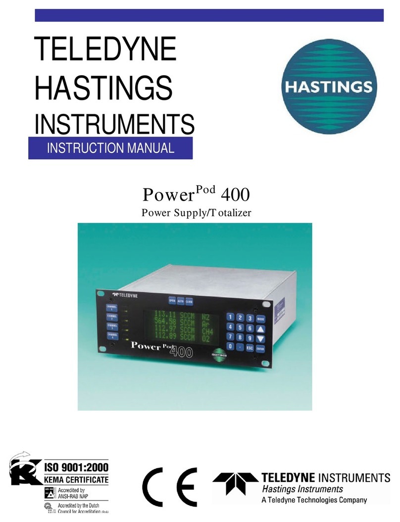
TheDISPLAYswitch,locatedintheupperright handcornerofthe front panel,controlsthe digital
display(refertoFigure2.3). When theDISPLAYswitchisin the FLOW position,thedisplayis
monitoring the mass flowrate. IftheDISPLAYswitchisintheCOMMANDposition the display
ismonitoringthe desired flow rate,alsoreferredto as thecommandsignal,for flow controllers
only. Ifthepowersupply waspurchasedwiththeflowinstruments,thepowersupplywillbe
alreadyset upso that the display reads directly in the unitsof flowto bemonitored.
EXAMPLE: A 5 SLPM unit is connected to channel 1. When the CHANNEL SELECTOR
switch is turned to channel 1,the display will read 5.00 at 5 SLPM flow rate. A 50 SCCM unit will
have the display for its channel read 50.0 at full flow. Note that the display has 3-1/2 digits,but
onlytwo decimal points are active, therefore a 1 SLPM unit willread 1000SCCM.
2.6.3 Channel Selection2.6.3 Channel Selection
2.6.3 Channel Selection2.6.3 Channel Selection
2.6.3 Channel Selection
TheCHANNEL SELECTOR switchin thelower right-hand cornerof the front panel isused to
switchthedisplaybetweenthe differentflowinstruments to bemonitored. Notethat the OFF
positionremovesallpowerfromthe flow instruments andfrom most of the powersupply. Ifthe
CHANNELSELECTORswitchis inadvertently turned totheOFFposition,the flow controller
valves willclose. After turningthe instrument back on,there will bea short period of timebefore
controlof the gasflow will resume.
2.6.4 Internal Command2.6.4 Internal Command
2.6.4 Internal Command2.6.4 Internal Command
2.6.4 Internal Command
Whenanexternal commandsignalis not providedtotheHastingsPowerSupply,it isgenerated
internally by applying a 5 voltreference to thecommand potentiometer on thefront panel. To set
thecommand,turntheDISPLAYswitchto theCOMMANDposition. Turnthechannel selector
switch to the channel to be set.The display is now reading the desired flow rate. Turn the com-
mandpotentiometerofthechannel to be changed clockwisetoincreaseflowrateand counterclock-
wisetodecrease flow rate.
2.6.5 External Command2.6.5 External Command
2.6.5 External Command2.6.5 External Command
2.6.5 External Command
TheHastingsPowerSupplycan be setupto accept anexternalcommand signal suchasthe output
from a D/A converter. When operating in this mode,the signal from the D/A converter is con-
nectedtothe external command inputterminalson the back ofthepower supply (see Figure2.4).
There is a plus (+) and a minus (-) terminal for each channel. NOTE: All four negative terminals
are tied together and to the flow common terminal inside the power supply. If this mode of
operationwasnotspecifiedon the original order, therewillbeaninternal dipswitch that must be
set. See Section 3.3 to set this. When operating with a 0-5 volt external command signal the
commandpotentiometer onthe frontpanelmustbe setfully clockwise. Thiswillresultin the
external command signalbeingsentdirectlytothe controller. Thecommandsignalcan be moni-
toredbyturningthe Flow/Command switch toCommand. Ifanexternal command signalgreater
than5voltsfullscale is used, applyfullscalecommandsignal and turn the commandpotentiometer
counterclockwiseuntilthedesiredfullscalecommandisdisplayed.
Figure2.4

