GMI PSD5201 Instruction Manual

PSD5201 - SIL 3 Power Supply for Hazardous Area Equipment G.M. International ISM0186-3
SIL 3 Power Supply
for Hazardous Area Equipment
DIN-Rail,
Model PSD5201
PSD5201
INSTRUCTION & SAFETY MANUAL

2 PSD5201 - SIL 3 Power Supply for Hazardous Area Equipment G.M. International ISM0186-3
General Description:
The PSD5201 is a single channel DIN Rail Power Supply able to drive measuring, process control equipment in IIB Group Hazardous Area, providing isolation between supply and
output.
A typical application is to drive high power devices, transmitters or other equipment with 14.5 V, 150 mA supply capability.
Mounting on standard DIN-Rail, in Safe Area or in Zone 2.
Functional Safety Management certification:
G.M. International is certified by TUV to conform to IEC61508:2010
part 1 clauses 5-6 for safety related systems up to and included SIL3.
Technical Data
Characteristics
Supply:
24 Vdc nom (21.5 to 30 Vdc) reverse polarity protected, ripple within voltage limits ≤5 Vpp, 2 A time lag fuse internally protected.
Current consumption @ 24 V: 200 mA with 150 mA nominal load, 210 mA with short circuited output.
Power dissipation: 2.5 W with 24 V supply voltage and 150 mA nominal load.
Isolation (Test Voltage):
I.S. Out/Supply 1.5 KV.
Output:
150 mA at 14.5 V (20 V no load, 36.4 Ωseries resistance).
Short circuit current: ≥155 mA.
Compatibility:
CE mark compliant, conforms to Directive: 2014/34/EU ATEX, 2014/30/EU EMC, 2014/35/EU LVD, 2011/65/EU RoHS.
Environmental conditions:
Operating: temperature limits – 40 to + 70 °C, relative humidity 95 %, up to 55 °C.
Storage: temperature limits - 45 to + 80 °C.
Safety Description:
ATEX: II 3(1)G Ex nA [ia Ga] IIB T4 Gc, II (1)D [Ex ia Da] IIIC, I (M1) [Ex ia Ma] I
IECEx: Ex nA [ia Ga] IIB T4 Gc, [Ex ia Da] IIIC, [Ex ia Ma] I,
UKR TR n. 898: 2ExnAiaIICT4 X, ExiaI X
associated apparatus and non-sparking electrical equipment.
Uo/Voc = 21.5 V, Io/Isc = 604 mA, Po/Po = 3243 mW at terminals 13/15-14/16.
Um = 250 Vrms, -40 °C ≤Ta ≤70 °C.
Approvals:
BVS 14 ATEX E 023 X conforms to EN60079-0, EN60079-11, EN60079-15.
IECEx BVS 14.0019X conforms to IEC60079-0, IEC60079-11, IEC60079-15.
CЦ16.0036 X conforms to ДСТУ 7113, ГОСТ 22782.5-78, ДСТУ IЕС 60079-15.
TÜV Certificate No. C-IS-236198-04, SIL 2 / SIL 3 conforms to IEC61508:2010 Ed.2.
TÜV Certificate No. C-IS-236198-09, SIL 3 Functional Safety Certificate conforms to IEC61508:2010 Ed.2, for Management of Functional Safety.
Mounting:
T35 DIN Rail according to EN50022.
Weight: about 145 g.
Connection: by polarized plug-in disconnect screw terminal blocks to accomodate terminations up to 2.5 mm2.
Location: Safe Area or Zone 2, Group IIB T4 installation.
Protection class: IP 20.
Dimensions: Width 22.5 mm, Depth 123 mm, Height 120 mm.
2
4
6
8
10
12
14
16
18
20
22
V (V)
I (mA)
0
PSD5201 Output Diagram
Vo 20 V (no load)
Rout 36.4
Ilim 155 mA
300 60 90 120 150 180
155
14.5
FSM
SIL 3

3
PSD5201 - SIL 3 Power Supply for Hazardous Area EquipmentG.M. International ISM0186-3
Ordering Information
Front Panel and Features
SIL 3 according to IEC61508:2010 Ed. 2 for NE Loads for Tproof = 2 / 10 years (≤10% / >10 % of total SIF).
SIL 2 according to IEC61508:2010 Ed. 2 for NE Loads for Tproof = 20 years (≤10% of total SIF).
PFDavg (1 year) 4.33 E-05, SFF 91.15 %.
Systematic capability SIL 3
Output to Zone 0 (Zone 20), installation in Zone 2.
High output capability Power Supply for Hazardous Area equipment.
Output short circuit proof and current limited.
Isolation Supply/Output.
EMC Compatibility to EN61000-6-2, EN61000-6-4, EN61326-1, EN61326-3-1 for safety system.
ATEX, IECEx, UKR TR n. 898, TÜV Certification.
Simplified installation using standard DIN Rail and plug-in terminal blocks.
250 Vrms (Um) max. voltage allowed to the instruments associated with the module.
+ Output for high power device
Terminal block connections
HAZARDOUS AREA SAFE AREA
- Output for high power device
13/15
14/16
Model: PSD5201
12 11 10 9
+ Power Supply 24 Vdc
9
- Power Supply 24 Vdc
10
7 8
7 8
13 14 15 16

4 PSD5201 - SIL 3 Power Supply for Hazardous Area Equipment G.M. International ISM0186-3
Parameters Table
Must
be
Hazardous Area/
Hazardous Locations
Device Parameters
PSD5201 Associated
Apparatus Parameters
Must
be
Hazardous Area/
Hazardous Locations
Device + Cable Parameters
Uo / Voc = 21.5 V Ui / Vmax
In the system safety analysis, always check the Hazardous Area/Hazardous Locations devices to conform with the related system documentation, if the device is Intrinsically Safe check
its suitability for the Hazardous Area/Hazardous Locations and group encountered and that its maximum allowable voltage, current, power (Ui/Vmax, Ii/Imax, Pi/Pi) are not exceeded
by the safety parameters (Uo/Voc, Io/Isc, Po/Po) of the PSD5201 series Associated Apparatus connected to it. Also consider the maximum operating temperature of the field device,
check that added connecting cable and field device capacitance and inductance do not exceed the limits (Co/Ca, Lo/La, Lo/Ro) given in the Associated Apparatus parameters for the
effective group. See parameters indicated in the table below:
PSD5201 Terminals
13/15-14/16
≤
PSD5201 Terminals PSD5201 Associated Apparatus
Parameters Cenelec (US)
Ci / Ci device + C cable≥
IIB (C)
Co / Ca = 1.2 µF
Co / Ca = 4.5 µF IIA (D)
IIB (C)
Lo / La = 0.39 mH
Lo / La = 0.78 mH IIA (D)
Io / Isc = 604 mA Ii/ Imax≤
Po / Po = 3243 mW Pi / Pi≤
13/15-14/16 Li / Li device + L cable≥
IIB (C)
Lo / Ro = 43.8 µH/Ω
Lo / Ro = 87.7 µH/ΩIIA (D) Li / Ri device and
L cable / R cable
≥
For installations in which both the Ci and Li of the Intrinsically Safe apparatus exceed 1 % of the Co and Lo parameters of the Associated Apparatus (excluding the cable),
then 50 % of Co and Lo parameters are applicable and shall not be exceeded (50 % of the Co and Lo become the limits which must include the cable such that
Ci device + C cable ≤50 % of Co and Li device + L cable ≤50 % of Lo).
If the cable parameters are unknown, the following value may be used: Capacitance 180pF per meter (60pF per foot), Inductance 0.60µH per meter (0.20µH per foot).
I
Co / Ca = 6.5 µF
Co / Ca = 1.2 µF IIIC (E, F, G)
I
Lo / La = 1.28 mH
Lo / La = 0.39 mH IIIC (E, F, G)
I
Lo / Ro = 143.9 µH/Ω
Lo / Ro = 43.8 µH/ΩIIIC (E, F, G)

5
PSD5201 - SIL 3 Power Supply for Hazardous Area EquipmentG.M. International ISM0186-3
Function Diagram
HAZARDOUS AREA ZONE 0 (ZONE 20)
GROUP IIB SAFE AREA, ZONE 2 GROUP IIB T4
MODEL PSD5201
13/15
14/16
9 +
10 - Supply 24 Vdc
+
-
Out
2 wire
Device
Solenoid
Valve
+
-
I
?
=
=

6 PSD5201 - SIL 3 Power Supply for Hazardous Area Equipment G.M. International ISM0186-3
Functional Safety Manual and Application
Application of PSD5201 for NE load
Failure category Failure rates (FIT)
λdd = Total Dangerous Detected failures 0.00
λdu = Total Dangerous Undetected failures 9.86
λsd = Total Safe Detected failures 0.00
λsu = Total Safe Undetected failures 101.50
λtot safe = Total Failure Rate (Safety Function) = λdd + λdu + λsd + λsu 111.36
MTBF (safety function, single channel) = (1 / λtot safe) + MTTR (8 hours) 1025 years
λno effect = “No Effect” failures 133.64
λnot part = “Not Part” failures 9.60
λtot device = Total Failure Rate (Device) = λtot safe + λno effect + λnot part 254.60
MTBF (device, single channel) = (1 / λtot device) + MTTR (8 hours) 448 years
λsd λsu λdd λdu SFF
0.00 FIT 101.50 FIT 0.00 FIT 9.86 FIT 91.15%
Failure rates table according to IEC 61508:2010 Ed.2 :
Failure rate table:
Safety Function and Failure behavior:
PSD5201 is considered to be operating in Low Demand mode, as a Type A module, having Hardware Fault Tolerance (HFT) = 0.
The failure behaviour of PSD5201 for NE loads is described by the following definitions :
□Fail-Safe State: it is defined as the output voltage being deviated below 2 Vdc.
□Fail Safe: failure mode that causes the module / (sub)system to go to the defined fail-safe state without a demand from the process.
□Fail Dangerous: it is defined as a failure that does not respond to a demand from the process (i.e. being unable to go to the defined fail-safe state), so that the output voltage is
deviated between 2 and 12 Vdc or above 22 Vdc.
□Fail “No Effect”: failure mode of a component that plays a part in implementing the safety function but that is neither a safe failure nor a dangerous failure, so that the output
voltage is deviated between 12 and 22 Vdc. When calculating the SFF, this failure mode is not taken into account.
□Fail “Not part”: failure mode of a component that is not part of the safety function but part of the circuit diagram and is listed for completeness. When calculating the SFF, this
failure mode is not taken into account.
Failure rate data: taken from Siemens Standard SN29500.
Description:
In normal operation the module is powered by connecting 24 Vdc nominal input supply to Pins 9 (+ positive) - 10 (- negative). The green LED is lit in presence of input supply.
In this condition the Output NE load (connected to positive pins 13/15 and to negative pins 14/16) is Normally Energized (NE).
In case of de-energized to trip operation, the module is shutdown and output load is de-energized (Safe State).
The following table describes the state (de-energized or energized) of output when input supply is present or absent:
Operation Input Supply State
Pins 9(+) - 10 (-)
Output State
Pins 13/15(+) - 14/16 (-)
Normal Present (24 Vdc nominal, 21.5 to 30 Vdc range) Energized
Trip Absent (0 Vdc) De-energized (as safe state condition)
De-energized to trip operation
Output is de-energized
PSD5201
9 +
10 -
Supply
24 Vdc
13/15
Out
2 Wires
Device
+
-
Normal state operation
Output is energized
Solenoid
Valve
+
-
?
I 14/16 PSD5201
9 +
10 -
Supply
0 Vdc
13/15
Out
2 Wires
Device
+
-
Solenoid
Valve
+
-
?
I 14/16
T[Proof] = 1 year T[Proof] = 2 years
PFDavg = 4.33E-05 Valid for SIL 3 PFDavg = 8.65E-05 Valid for SIL 3
PFDavg vs T[Proof] table (assuming Proof Test coverage of 99%), with determination of SIL supposing module contributes >10% of total SIF dangerous failures:
PFDavg vs T[Proof] table (assuming Proof Test coverage of 99%), with determination of SIL supposing module contributes ≤10% of total SIF dangerous failures:
T[Proof] = 10 years T[Proof] = 20 years
PFDavg = 4.33E-04 Valid for SIL 3 PFDavg = 8.65E-04 Valid for SIL 2
Systematic capability SIL 3.

7
PSD5201 - SIL 3 Power Supply for Hazardous Area EquipmentG.M. International ISM0186-3
The PSD5201 series devices are isolated Intrinsically Safe Associated Apparatus installed into standard EN50022 T35 DIN-Rail located in Safe Area or Zone 2, Group IIB, Temperature
T4, Hazardous Area (according to EN/IEC60079-15) within the specified operating temperature limits Tamb –40 to +70 °C, and connected to equipment with a maximum limit for
AC power supply Um of 250 Vrms.
Not to be connected to control equipment that uses or generates more than 250 Vrms or Vdc with respect to earth ground.
The PSD5201 series must be installed, operated and maintained only by qualified personnel, in accordance with the relevant national/international installation standards (e.g. IEC/
EN60079-14 Electrical apparatus for explosive gas atmospheres - Part 14: Electrical installations in hazardous areas (other than mines)), following the established installation rules;
particular care must be given to segregation and clear identification of I.S. conductors from non I.S. ones.
De-energize the power source (turn off the power supply voltage) before plugging or unplugging the terminal blocks when installed in Hazardous Area or unless the area is known to be
non-hazardous.
Warning: substitution of components may impair Intrinsic Safety and suitability for Zone 2.
Explosion Hazard: to prevent ignition of flammable or combustible atmospheres, disconnect power before servicing or unless the area is known to be non-hazardous.
Failure to proper installation or use of the equipment may risk to damage the unit or cause severe personal injury.
The unit cannot be repaired by the end user and must be returned to the manufacturer or his authorized representative.
Any unauthorized modification must be avoided.
Warning
Operation
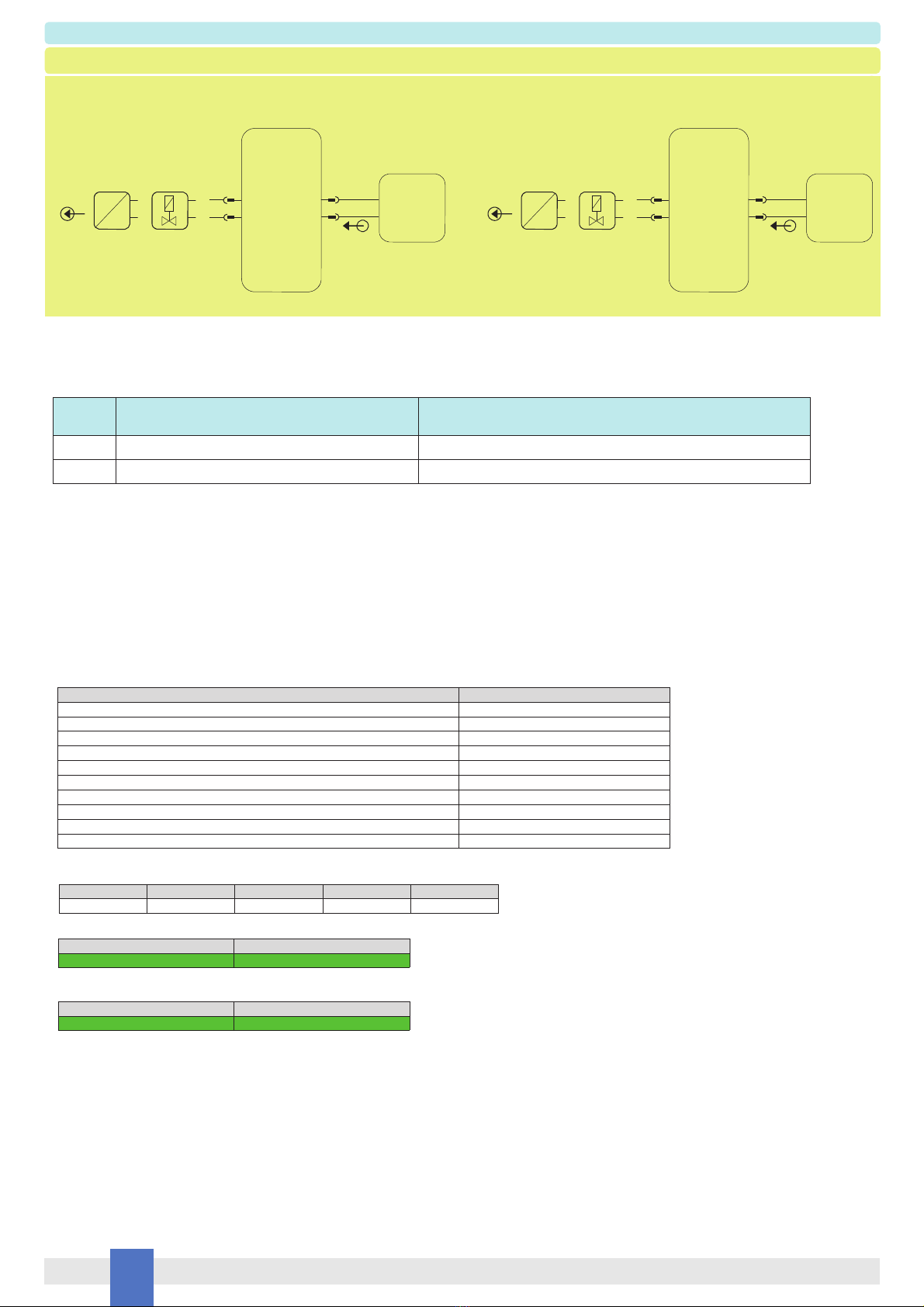
The PSD5201 module provides an output (see the output diagram in the “Technical Data” section for the details of the voltage and current provided to the load) in IIB Group Hazardous
Area to drive IntrinsicallySafe loads, typically high power devices, transmitters or other measuring or process control equipment.
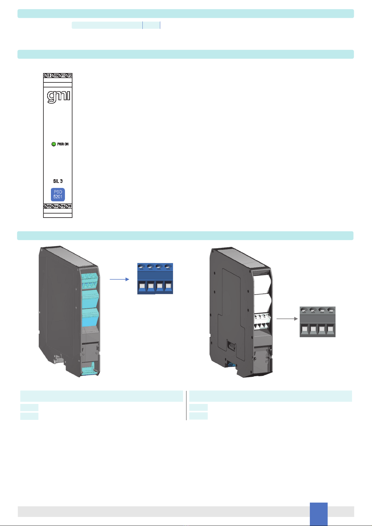
The module provides full electrical isolation between supply and output and a “POWER ON” green led is lit when the unit is supplied.
Installation
The PSD5201 series devices are IIB Group power supplies for field devices housed in a plastic enclosure suitable for installation on T35 DIN-Rail according to EN50022,.
The PSD5201 unit can be mounted with any orientation over the entire ambient temperature range.
Electrical connection of conductors up to 2.5 mm² are accommodated by polarized plug-in removable screw terminal blocks which can be plugged inside/outside a powered unit without
suffering or causing any damage (for Zone 2 installations check the area to be non-hazardous before servicing).
The wiring cables have to be dimensioned according to their current and length.
In the “Function Diagram” section and on the enclosure side, a block diagram identifies all connections.
Identify the function and location of each connection terminal using the wiring diagram in the corresponding section, for example:
Connect a 24 Vdc power supply voltage between terminals “9” (positive pole) and “10” (negative pole).
Connect the output load between terminals “13” / “15” (positive pole) and “14” / “16” (negative pole).
Intrinsically Safe conductors must be identified and segregated from non I.S. ones and wired in accordance with the relevant national/international installation standards (e.g. EN/
IEC60079-14 Electrical apparatus for explosive gas atmospheres - Part 14: Electrical installations in hazardous areas (other than mines)); make sure that conductors are well isolated
from each other and do not produce any unintentional connection.
The enclosure provides, according to EN60529, an IP20 minimum degree of mechanical protection (or similar to NEMA Standard 250 type 1) for indoor installation; outdoor installation
requires an additional enclosure with higher degree of protection (i.e. IP54 to IP65 or NEMA type 12-13) consistent with the effective operating environment of the specific installation.
Units must be protected against dirt, dust, extreme mechanical (e.g. vibration, impact and shock) and thermal stress, and casual contacts.
If the enclosure needs to be cleaned, use only a cloth lightly moistened by a mixture of detergent in water.
Electrostatic Hazard: to avoid electrostatic hazard, the enclosure of PSD5201 must be cleaned only with a damp or antistatic cloth.
Any penetration of cleaning liquid must be avoided to prevent damage to the unit. Any unauthorized modification must be avoided.
According to EN61010, the PSD5201 series must be connected to SELV or SELV-E supplies.
Start-up
Before powering the unit, check that all wires are properly connected, in particular supply conductors and their polarity and output wires; also check that Intrinsically Safe conductors and
cable trays are segregated (that is, they must have no direct contacts with other non I.S. conductors) and identified either by color coding, preferably blue, or marking.
Check conductors for exposed wires that could touch each other causing dangerous unwanted shorts. When the power supply voltage is turned on, the “power on” green led must be lit
and the output must be able to power the Hazardous Area load according to the output diagram shown in the “Technical Data” section.
The proof test shall be performed to reveal dangerous faults which are undetected by diagnostic. This means that it is necessary to specify how dangerous undetected fault, which
have been noted during the FMEDA, can be revealed during proof test. The Proof test consists of the following steps:
Testing procedure at T-proof
Steps Action
1 Bypass the safety-related PLC or take any other appropriate action in order to avoid a false trip.
2 Supply the PSD5201 module by means of a DC power source connected between terminals 9-10, whose value must be comprised between 21.5 and 30 Vdc.
Connect a current calibrator to the output terminals (13/15-14/16) and impose an output load condition up to 150 mA. Also connect a DC voltmeter between the
output terminals (13/15-14/16). In this condition, the output voltage, measured by means of the DC voltmeter, should always be comprised between around 14.5
Vdc (for a 150 mA output load condition) and around 20 Vdc (for a 0 mA output load condition). If, on the other hand, an output voltage comprised between 2 and
12 Vdc or above 22 Vdc is measured, a dangerous failure which has produced a wrong output voltage deviation is detected.
3 Use the same setup described in the previous step and measure, by means of an AC voltmeter, the rms value of the output voltage. In normal operation conditions,
the output supply voltage should have no AC component, that is its rms value should be ideally null. If an rms value well above 0 Vrms is measured (a reasonable
value could be 50% of the power supply line value, i.e. 12 Vrms compared to 24 Vdc), a dangerous failure which has produced an oscillation of the output circuit is
detected.
4 Restore the loop to full operation.
5 Remove the bypass from the safety-related PLC or restore normal operation.
This test will reveal approximately 99 % of possible Dangerous Undetected failures in the repeater.
Table of contents
Other GMI Power Supply manuals