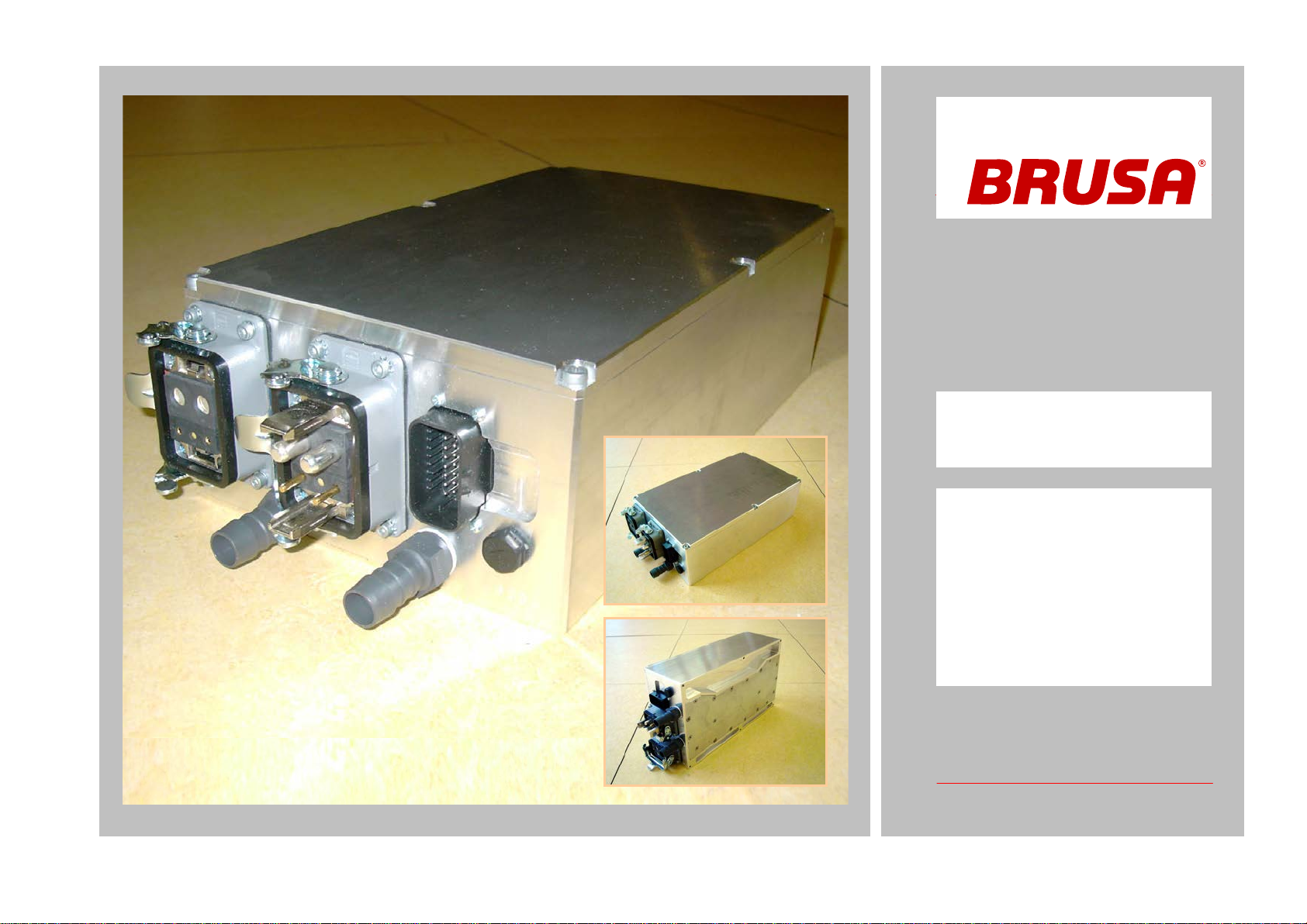
Betriebsanleitung BDC412 User’s manual BDC412
11.2016-BDC412_User Manual_V15.doc 5 / 45
•
Lassen Sie das Gerät durch einen Fachmann im
Fahrzeug installieren und in Betrieb nehmen.
•
Öffnen Sie keinesfalls das Gerät ohne vorherige
Rücksprache mit dem Werk.
•
Stecken Sie niemals die Hochspannungsstecker ein
ohne vorher sicherzustellen, dass das Gerät vom
restlichen Hochspannungskreis getrennt ist (z.B.: im
Fahrzeug durch Schütze).
•
Trennen Sie niemals die Hochspannungsstecker
vom Gerät oh
ne vorher sicherzustellen, dass keine
Hochspannung mehr anliegt.
•
Verwenden Sie einen Isolationswächter für die
Überwachung der galvanischen Trennung zwischen
Hoch- und Niederspannungskreis.
•Have the unit installed and made operational by a
skilled professional.
•Do not open the unit without contacting the manu-
facturer before.
•
Do not connect the high voltage connectors before
being sure the device is separated from the high
voltage DC-link (e.g.: in a vehicle by contactors).
•Never disconnect the high voltage connectors be-
fore being sure that there is no high voltage on the
DC-link anymore.
•
Use an insulation failure detector in order to monitor
the galvanic insulation between the high and the low
voltage DC-link.
Um einen Schaden am Gerät zu vermeiden
•Stellen Sie sicher, dass im Hochspannungskreis Si-
cherungen oder Schütze verwendet werden, um bei
Fehlerzuständen wie High-Side Spannung < Low-
Side Spannung (z.B.: Kurzschluss der High-Side
und Anschluss einer Batterie auf Low-Side) Be-
schädigungen des Gerätes zu vermeiden.
•Sorgen Sie für ausreichende Kühlung des Gerätes.
Eine niedrige Kühlwassertemperatur kann die Le-
bensdauer beträchtlich erhöhen.
•Vermeiden Sie den Betrieb nahe an Wärmequellen
oder in direkter Sonnenstrahlung.
•Trotz des hohen IP-
Schutzes empfehlen wir, das
Gerät soweit als möglich von Umweltein
Regen oder Spritzwasser zu schützen.
To prevent from damage of the device
•Ensure that for the high voltage circuit fuses or con-
tactors are used in order to prevent the unit from
damage in case of failure conditions like high-side
voltage < low-
side voltage (e.g.: short circuit on
high-side and battery connected to low-side).
•Ensure sufficient cooling of the device. A low tem-
perature of the cooling water has a considerable
positive effect on the lifetime.
•
Avoid operation of the device next to a heat source
or in direct sunlight.
•Even though the high IP-
to not expose the unit to rain or splash water.