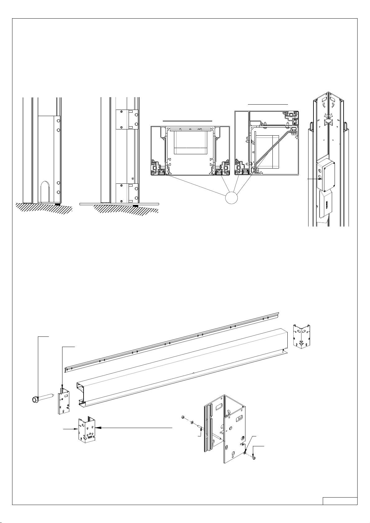
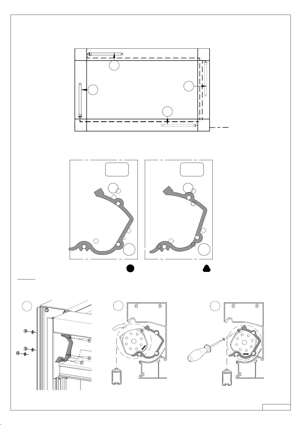
BRUSTOR B300XL User manual

B300(XL)-ODL
BRUSTOR
®
OUTDOOR SUN SYSTEMS
www.brustor.com
HOLIDAY AT HOME
Mounting instructions
GB
V2018 04

0. OVERVIEW
1. PLACING THE SUPPORTS
1.a Stand Alone
1.b Wall Fixation
2. PLACING THE VERTICAL POLES
3. MOUNTING THE CROSS MEMBERS
4. ADJUSTING THE CONSTRUCTION
4.a Levelness
4.b Perpendicularity
5.
SCREENS
5.a Rollertubes
5.b Motorcable
6. DRAIN
7. SCREENGUIDES
7.a Guides Leadrail
7.b PVC- guides
8. ASSEMBLY SLIDING COVER
8.a Arms and rollertube
8.b Corner reinforcement
8.c Extensie vertical pole
8.d Drain side
8.e Mounting the fabric
8.f Mounting the fabric fixation rail
9. FINISHING ROOF
9.a Coverplates W-and L-side
9.b Rooftop covers
10. PROGRAMMING THE SCREENMOTOR AND FABRIC MOTOR
11. SCREEN COVER
12. PLACING THE RAIN GUTTERS
12.a Corner piece
12.b Rain gutter
13. FINISHING
13.a Drain
13.b Cover vertical poles
14. WIRE DIAGRAM
14.a Electricity grid
14.b Screens
01
02
02
03
04
04
07
07
07
08
08
09
10
11
11
11
12
12
14
14
15
15
16
18
18
19
20
20
21
21
22
22
22
23
23
23
23

OL-B300-01
Single Couple
0. OVERVIEW
› Check if all parts are present, and check if the dimensions are as ordered
Pole Support coupled unit (standard)
Cover vertical coupling pole
Vertical coupling pole
(pre-assembled screenguide)
Support for ground anchor
or floor plate for coupling pole
Vertical pole
(pre-assembled screenguide)
Cover vertical pole
Fixation for groundanchor
Drain
(Tube D50 not
delivered)
Corner reinforcement
Co
ver plate L-side
Corner drain
Rain gutter
Roof cover
Screen housing
Extension vertical pole
Arm
Fabric
Fabric fixation rail
Motor
Rollertube
Cover plate W-side
Roof cover
Cover flowprofile
Roof cover support
Flowprofile
Top cover vertical pole
First louvre
Groundanchor
Floorplate 20x20
Pole Support (standard)

OL-B300-02
1. PLACING THE SUPPORTS
› Place the supports as indicated on the following drawings.
› Check the diagonals, the difference should not be more than 5mm.
1.a STAND ALONE
W
L
W
L
L - 3-1/2”
W - 3-1/2” W - 3-1/2”
L - 3-1/2”
=
=
=
=
Pole Support Ground Anchor Floorplate 20x20
W
L
L
L - 3-1/2”
W - 1-3/4” W - 1-3/4”
L - 3-1/2”
W
=
=
=
=
Pole Support Ground Anchor Floorplate 20x20
SINGLE
COUPLE
W
L
W
L
=
=
W - 3/8”
W - 1/4”
=
=
L - 3/8”
L -3/8”
L - 3/4”

OL-B300-03
L
w
W - 9-7/8”4-7/8” 4-7/8”
1.b WALL FIXATION
1/4”
L
W
W - 9-7/8”4-7/8” 4-7/8”
4-7/8”
1/4”
SINGLE
COUPLE
› Use the dimensions mentioned above, but add 5mm next to the wall.
H-4-3/8”
H
1/4”
5-1/2”
1/4”

OL-B300-04
Pole Support Floorplate 20x20
Groundanchor
Electrical
supply
SINGLE POLE
COUPLING POLE
2. PLACING THE VERTICAL POLES
› Remove the Pole supports from the vertical poles, also remove the premounted screenguides, and the reinforcement (1)
› Attach the pole supports or floorplates onto the floor.
› Check the dimenions from the previous page again, before fastening the bolts.
› Place the vertical pole over the supports.
› Make sure that the pole is mounted perfectly vertical.
› If necessary fill up the bumps.
› One of the poles contains the electrical supply for the louvremotor and, possibly, the led lights.
Make sure this pole is placed on the right position (according to your order).
3. MOUNTING THE CROSS MEMBERS
› In case of wallfixation, screw the short poles on to the side of the cross members.
› For a coupled unit prepare the junction part, as shown on the drawing below.
› Hook the cross members on to the walladapter.
1
2 x 4 DIN7504K 6.3x50
Coupling pole
Threaded rod M6x130
DIN 934 M6
washer DIN 125 M6
Single pole

OL-B300-05
› Hook the cross members on to the vertical poles. (1)
› Completely tighten both screws.
› Screw the two lower screws in the profile. (2)
Make sure the mainhousing is well positioned compared to the hole in the pole.
› In case of wallfixation, secure the cross member by mounting a bolt
on both sides of the screen. (3)
ROOF IN 2 PARTS
› On both ends of the screen, screw four bolts in the profile (M8x25). Do not fasten them completely,
leave 10 to 15mm free space.
› Make sure a gasket is placed at the end of the profile.
› Hook the middleguide between the 2 screenboxes (1)
› Secure both sides of the middleguide with 4 bolts (M8x25) through the mainhousing.
10 a 15
› Remove the rollertubes from the screens.
› On both ends of the screen, screw the two upper screws in the profile (6.3x50) (1 screw if coupled).
› Do not fasten them completely, leave 10 to 15mm free space.
SW10
4x
123
long bolt
SINGLE
walladapter
!
DIN 912 M8x25
Gasket
3/8” to 1/4”
3/8” to 5/8”

OL-B300-06
Coupling profile
12
3
1
COUPLE
DOOR PROFILE
› Remove the rollertubes from the screens.
› Position the doorprofile below the structure and fix it. (1)
› Make sure the post is flush with the main housing. (2)
4 x DIN 912 M8x25
Coverplate couple pole
wall fixation
6.3 x 50
Gasket
Walladapter
Walladapter
M8 x 25
M8 x 80
12
!

OL-B300-07
4 ADJUSTING THE CONSTRUCTION
› Check the top side of the construction with a laser or a level.
› If necessary, adjust the construction
› Move the vertical poles upward untill the top side of the contruction is completely level.
› If necessary use some provisional filling.
4.a LEVELNESS
› Check the perpendicularity trough the following dimension. (L1 ± 2mm !)
› Also check the diagonals of the top side.
› If necessary, the pole supports allow a small adjustment..
L1
L1
L2
L2
4.b PERPENDICULARITY
L3
L3
Pole Support Floorplate 20x20
Groundanchor
Sideview
Topview
› Once everyting has been adjusted, tighten all the bolts.
› Remove the provisional filling
(L1 ± 1/8” !)

OL-B300-08
› If there are 3 or 4 screens, start with the screenswith the longest distance from the electrical supply.
(number 1 on the following diagram)
5. SCREENS
220V
1
1
2
2
5.a ROLLERTUBE
SINGLE
› The rollertube support can be installed in 2 different ways depending on the type of fabric, see drawing underneath.
› Before installing the rollertube suports, the gaskets should be pierced.
› Attach the rollertube supports to the vertical poles (3 x M6x25) (1)
› Insert the screens as shown below (2), and secure them on both sides (M4x20) (3).
123
PVC (without window) PVC with window

OL-B300-09
COUPLE/DOORPROFILE
5.b MOTORCABLE
› Fix the rollertube support on the vertical poles as shown underneath.
› Do “not” use a ring on the side where the rollertube support is installed.
› Two rollertube supports can be installed at each pole
› Tilt the screen in the brackets as shown on the drawing (2), and secure them at both ends (M4x20) (3).
› Place the cable as shown below.
› numbers 2 and 3 only count for the most distant screens (number 1 on the diagram on top of this page)
› Hide the cable behind the PVC fabric protection
› In some cases it may be necessary to hide the cable behind its own rollertube !
Ring only needed if
no rollertube support
has to be installed
1
1
2322
23

OL-B300-10
SINGLE COUPLE
Cable screenmotor (nr 2 on previous page)
Cable screenmotor (nr 1 on previous page)
Cable screenmotor (nr 2 on previous page)
6. DRAIN
› After installing all the motors, the vertical pole with the electrical supply should look like this:
› The number of cables depend on the numbers of screens that have been installed.
› The connection of the cables will be explained later on.
› Place in one or more vertical pole a support for the drain.
› Preferably, the drain is placed at the lowest side of the roof. (1 drain every 15m²)
› Tighten all bolts.
› The water evacuation pipe can not be installed in a door profile.
(1 drain every 49ft
2
)

OL-B300-11
7.a GUIDES LEADRAIL
7.b PVC - GUIDES
7 SCREEN GUIDES
›WARNING when opening a side guide.
› When opening a side guide you must start at the upper clips and go down one by one.
› Pull as close as possible on the clips profile in order not to deform it.
1
2
3
› While mounting the plastic guides, place the leadrail on top of the screen.
› Place the plastic guides in the groove under the rollertube.
› Slide them completely to the left and right side of the screen, and secure them with two screws.
› Push the pieces down while thighting the screws.
› Slide the leadrail, left and right, in the plastic guides and lower the fabric 30cm.
› Slide the PVC-guide over the zipper that has been welded to the fabric.
› Hook the cover over the PVC-guide.
› Close the guide at the bottom, and move the cover down over the pins that are mounted on the bottom of the guides.
› Close the guide completely.
4.2 x 6.5
11-3/4”.

OL-B300-12
8 ASSEMBLY SLIDING COVER
8.a ARMS AND ROLLERTUBE
› Place the arm on the mainhousings and make sure that the end and head piece cover the inserts M6.
› The arm with the longest hooks is positioned on the side to which you want the rainwater to flow, with the arm with the
shortest hooks on the other side. With a construction with 3 arms you position the third arm in the middle.
› Position the arm parallel to the frame and place the outer arms right next to the vertical poles. See drawing.
› Make sure the attachment lip on the rollertube-side of the arm is directed to the inside.
› Tension the bolts at the end and head piece.
1. STAND ALONE 2. ENCLOSED MODULE
1. STAND ALONE
12
W2
W2
DIN7504 Ø4,2x13
DIN933 M6x25
DIN9021 M6
insert M6
0
Attachment lip
W2 W1

OL-B300-13
2. ENCLOSED
› The arm with the longest hooks is positioned on the side to which you want the rainwater to flow, with the arm with the
shortest hooks on the other side. With a construction with 3 arms you position the third arm in the middle.
› Place the arms on the main housings and slide them together to the bearing-side just above the main housing L-side. (1)
› Make sure the first trolley of each arm is in the same position (see previous page).
› Slide the rollertube through both arms, first through the arm on the motor-side. (2)
› Split up the arms again until they are positioned right next to the vertical poles. Then put the head piece and end piece of
both arms over the socket set screws . (3)
› Put the nuts on the socket set screws at the head and end piece. (3)
Arm motor-side
Arm bearing-side
1
2
Arm motor-side
Arm bearing-side Rollertube
Rollertube
Motor
› Check if the first trolley of each arm is in the same position (dimension A)
› In case it's not, turn the belt until they are in the same position.
› After checking the position, slide the rollertube through the bearings, first slide through the arm at the motor side.
TOPVIEW
First trolley's
A
SIDE VIEW
First trolley
Arm motor-side

OL-B300-14
3
sw104x
› Slide the corner reinforcement back in the pole and make sure it's placed half in the pole, half in the extension.
› Tighten the bolts in order to fix the corner reinforcement.
8.c EXTENSION VERTICAL POLE
› Take the corner reinforcement out of the pole and place the pole extension on the pole, with the holes directed to the arm.
› Guide the motor cable through the big hole and fix the motor with 2 screws.
8.b CORNER REINFORCEMENT

OL-B300-15
8.e MOUNTING THE FABRIC
› On the first fabric fits a smaller profile than on the others. This is the fabric fixation rail that will be mounted on the
frame at the rollertube-side (W2-side). The rainwater will flow to the widest side of the fabric. This is the L1 or L2 side
that you opted for when ordering and cannot be changed (see figure).
8.d DRAIN SIDE
y
x
WATER
Fabric fixation rail Last flow profile
First fabric Last fabric
W1
L2
W2
L1
Rollertube
› Provide each flow profile with 2 hooks at the ends of the profile and fix these.
› The plate of the hook has to come as far as the side of the profiile.
› In case of a 3 arm system, provide a hook in the middle of each profile.
2x sw10
› Make sure that the arms are in the correct order. The arm with the longest hooks is on the side to which the rainwater
must flow (see figure).
FLOW

OL-B300-16
› Hook the first flow profile in the first trolleys, the second flow profile into the second trolleys,...
› Unhook the first flow profile from the trolley, and unclip the cover from the flow profile.
› Slide the profile out of the fabrics.
8.f MOUNTING THE FABRIC FIXATION RAIL
› Screw the fabric fixation rail to the frame. (1)
› Re-slide the first flow profile on to the first and second fabric. (2)
› Clip the cover on the flow profile and hook the first flow profile into the first trolley. (3)
› Provide each trolley of a blocking. (4)
› Provide each flow profile with an end cap at both sides. (5)
Fabric fixation rail Fabric fixation rail
01
DIN7504 Ø4,2x13

OL-B300-17
04 05
drain
02 03

OL-B300-18
9. FINISHING ROOF
9.a COVERPLATES W-AND L-SIDE
› Place the 'cover plates L-side' on the frame with the long side towards the arms.
› Fix the coverplates on the frame, screw through the provided holes.
› Fix the second 'cover plate W-side' on the frame: slide the cover under the end pieces of the arm (1) and screw through
the provided holes. (2)
› In case of projection > 4m, also screw the cover on the arm through the provided holes in the middle of the cover. This
is to prevent bending of the profile.
Bending
L2 L1 L2 L1
W1
01
02
W1
DIN7504 Ø4,2x13
DIN7504 Ø4,2x13
L2 L1
2x DIN7504 Ø4,2x132x DIN7504 Ø4,2x13
Table of contents
Other BRUSTOR Outdoor Furnishing manuals
Popular Outdoor Furnishing manuals by other brands

PHI VILLA
PHI VILLA E02GS014 Use and care guide

Heart of House
Heart of House Jasmin 304/4733 Assembly instructions

Canvas
Canvas 088-0342-8 Assembly instructions

PHI VILLA
PHI VILLA F210004-A1 Use and care guide

Sunjoy
Sunjoy L-GZ098PST-1B Assembly instruction

vita
vita CLASSIC SPRINGPORT ARBOR VA68146 Assembly guide

HAMPTON BAY
HAMPTON BAY 5LGZ2011502-BW Use and care guide

Polywood
Polywood PLDCDB48 Assembly instructions

HAMPTON BAY
HAMPTON BAY FWS80486BG Use and care guide

Home Styles
Home Styles Tiki Bar 88 5662 98 Assembly instructions

HAMPTON BAY
HAMPTON BAY GSS00208A-4 Use and care guide

Polywood
Polywood Prescott ST57 Assembly instructions