Bryant 1625 User manual

GAPAA
PERFECT AIRtPURIFIER
SIZES 1625 AND 2025
Installation Instructions
NOTE: Read the entire instruction manual before starting the
install.
TABLE OF CONTENTS
PAGE
INTRODUCTION 1...................................
HOW IT WORKS 1...................................
SAFETY CONSIDERATIONS 1.........................
APPLICATION CONSIDERATIONS 2....................
INSTALLATION 3....................................
START--UP AND OPERATION 6........................
MAINTENANCE 7....................................
TROUBLESHOOTING 9...............................
SPECIFICATIONS AND DIMENSIONS 10................
WARRANTY 11......................................
INTRODUCTION
Congratulations for selecting the Perfect Air Purifier for your home
comfort system! The Perfect Air Purifier is proven to remove and
kill airborne germs and allergens, including viruses, bacteria, and
mold spores. The Perfect Air Purifier is a cornerstone of Bryant
Healthy Home Solutions for providing healthier, cleaner air in your
home.
HOW IT WORKS
The Perfect Air Purifier provides extremely high filtration
performance while killing captured contaminants, including
viruses, bacteria, and mold spores. The purifier treats the entire
air--stream through a state of the art, three--stage process.
In stage one, the particles are electrically charged by a
precision--point ionization array as they enter the purifier.
In stage two, the charged particles are electrically attracted to the air
purification cartridge, which is located within an electric field.
In stage three, captured particles are killed by electrical current
flow and ion bombardment.
The purifier is CSA certified for shock and electrical fire hazard
only.
La purifier certification CSA vise uniquement les risques de choc
electrique et.
A06054
Fig. 1 -- GAPAA UNIT
SAFETY CONSIDERATIONS
Improper installation, adjustment, alteration, service, maintenance,
or use can cause explosion, fire, electrical shock, or other
conditions which may cause death, personal injury or property
damage. Consult a qualified installer, service agency or your
distributor or branch for information or assistance. The qualified
installer or agency must use factory--authorized kits or accessories
when modifying this product. Refer to the individual instructions
packaged with the kits or accessories when installing.
Follow all safety codes. Wear safety glasses, protective clothing,
and work gloves. Have a fire extinguisher available. Read these
instructions thoroughly and follow all warnings and cautions
included in literature and attached to the unit. Consult local
building codes and the current edition of the National Electrical
Code (NEC) NFPA 70.
In Canada, refer to the current editions of the Canadian Electrical
Code CSA C22.1.
Recognize safety information. When you see this symbol on
the unit and in instructions or manuals, be alert to the potential for
personal injury. Understand the signal words DANGER,
WARNING,andCAUTION. These words are used with the
safety--alert symbol. DANGER identifies the most serious hazards,
which will result in severe personal injury or death. WARNING
signifies hazards, which could result in personal injury or death.
CAUTION is used to identify unsafe practices, which may result
in minor personal injury or product and property damage. NOTE
is used to highlight suggestions which will result in enhanced
installation, reliability, or operation.

2
APPLICATION CONSIDERATIONS
The Perfect Air Purifier is designed for use in the return air duct of
a forced air heating, cooling, and ventilation system. Models
GAPAAXBB1625 and GAPAAXBB2025 are specifically
designed for use in systems with a forced air gas furnace.
Air Conditioning
The purifier should be installed in a system so that all the return air
is circulated through the air purifier. It should be located upstream
of both the furnace and the air conditioning evaporator coil. This
will help keep the furnace and evaporator coil clean and prevent
condensation from forming within the purifier.
Humidifiers
An evaporative humidifier can be mounted upstream of the
purifier. It is best to install atomizing humidifiers downstream of
the air purifier because hard water salt deposits and water droplets
may damage air purifier. If an atomizing humidifier must be
mounted upstream of the purifier, it should be mounted as far
upstream as possible (at least 6 ft./1.8 m recommended), and a
standard disposable furnace filter should be mounted between the
humidifier and the air purifier to trap hard water salt deposits and
water droplets.
Ensure that the humidifier installation will not allow water or water
droplets to enter the air purifier because it may cause electrical
arcing or damage the air purifier.
NOTE: For fan coil installations, do not install the humidifier in
the fan coil access doors or cabinet.
Inspect for plugged drains and maintain humidifier drain lines on a
regular basis to avoid overflow of water into the air purifier. The
recommended inspection should be done at every change of the air
purifier cartridge (minimum, annually).
HIGH VOLTAGE HAZARD
Failure to follow this warning could result in personal injury
or death.
This air purifier utilizes high voltage. If you notice water
running into or around the air purifier, water stains on the
purifier cartridge or on the Enhancement Module walls or
cabinet, shut off the air purifier and call your service provider.
!WARNING
Transitions
If the return air duct or furnace openings do not fit the purifier
cabinet openings, gradual transitions are recommended to reduce
air turbulence and maximize efficiency. No more than 45_(about
8.5 in. per running ft.) of expansion should be used on each side of
the transition fitting.
Turning Vanes
If the purifier is installed adjacent to a 90_duct elbow, turning
vanes should be added inside duct to improve air distribution
across the face of the air purifier.
Electrical Power
The purifier should only be powered when airflow is present. The
furnace control EAC terminals provide power only when the
furnace blower is operating. Perfect Air Purifier models
GAPAAXBB1625 and GAPAAXBB2025 are designed to be
powered from the electronic air cleaner (EAC) terminals on a
furnace electronic control. If EAC terminals are not available, an
alternative airflow sensing mechanism must be used to ensure the
purifier is only powered when airflow is present. Contact local
Bryant distributor for information on approved alternatives.
Door (x1) Cabinet (x1) Enhancement Module (x1) Safety Screen (x1)
Installation Manual
Duct Gasket Tape
(1 roll)
Furnace Adapters (x2)
Return Duct Adapters:
Long (x2) / Short (x2)
Air Purification Cartridge (x1)
(x2)
(x2)
(x1)
(x1)
(x2)
Installation Components
(in bag attached to power cord)
A06064
Fig. 2 -- Perfect Air Purifier Components
GAPAA

3
INSTALLATION
Check Perfect Air Purifier Components
CUT HAZARD
Failure to follow this caution may result in personal injury.
Sheet metal parts may have sharp edges or burrs. Use care and
wear appropriate protective clothing and gloves when
handling parts.
CAUTION
!
Carefully remove all items from the box.
Identify Mounting Location
a. Identify a mounting orientation for the purifier in the return
air duct (see Figures 3 and 4).
b. Ensure airflow direction through the purifier matches the ar-
rows on the face of the air purifier cartridge. The purifier
can be rotated 180_to accommodate the cabinet orientation.
c. The location of the purifier should be readily accessible.
Enough room should be provided for periodic replacement
of the air purifier cartridges.
ELECTRIC SHOCK AND UNIT DAMAGE HAZARD
Failure to follow this warning could result in personal injury
or death.
Only a trained, experienced service person should install the
purifier. A thorough check of the unit installation should be
completed before unit operation. Before performing
installation, service or maintenance operations on unit, turn off
all power to unit. Tag disconnect switch with lockout tag.
!WARNING
Airflow
A
irflow
Upflow Furnace with Side Return
Horizontal Application
Upflow Furnace with Bottom Mount Downflow Furnace with Top Mount
Airflow
NOTE:
Mounting on this side
requires the cabinet
to be rotated 180° for
correct air flow.
Airflow
A06067
Fig. 3 -- Perfect Air Purifier Cabinet Orientation
GAPAA

4
Downflow 14” Furnace
with Top Mount
Upflow 14” Furnace
with Bottom Mount
Horizontal 14” Furnace
with Side Mount
Plenum
Box
Upflow Furnace
with Plenum Box
Horizontal 24” Furnace
Downflow 24” Furnace
with Top Mount
Upflow 24” Furnace On Stand
with Bottom Mount
Upflow Furnace
Note: When transitioning between two dierent sized components (furnace & purer), the
minimum transition angle at the larger of the two components must be no less than 45 degrees.
A09022
Fig. 4 -- Perfect Air Purifier Cabinet Orientation with Transition
Furnace
Adapters (x2)
Return Duct
A
dapters (x4)
Return Duct
Furnace
Adapters (x2)
Return Duct
Adapters (x4)
Return Duct
Top Mount Bottom Mount Side Mount
A06029
Fig. 5 -- Mounting Perfect Air Purifier Cabinet
GAPAA

5
Mount Cabinet
ELECTRICAL SHOCK HAZARD
Failure to follow this warning could result in personal injury
or death.
Before installing or servicing system, always turn off main
power to system. There may be more than 1 disconnect switch.
!WARNING
UNIT DAMAGE HAZARD
Failure to follow this caution may result in equipment
damage.
Cabinets will support a maximum weight of 400 lbs/181 kg
when installed beneath a vertical furnace or air--handling
unit. When setting furnace on cabinet, do not drop it into
place. Position the furnace correctly on the cabinet to prevent
a corner from slipping down and damaging the cabinet or its
components.
CAUTION
!
a. Turn off power to the heating and cooling system.
b. Remove the existing furnace filter and discard. Excessive
system static may result if the purifier is used with other fil-
tration devices.
c. Remove the air purifier cartridge and enhancement module
from the purifier cabinet.
d. Position the cabinet between the furnace and return air duct
(see Figures 3, 4, 5 and 6). A transition duct may be re-
quired.
e. Furnace adapters have been included for installer conveni-
ence. They are designed for top or bottom mount installa-
tions (see Fig. 6).
Furnace
Adapters
Airow
Airow
A05274
Fig. 6 -- Use of Furnace Adapters
f. Return air duct adapters have been included for installer
convenience. They should be used to connect the upstream
side of the air purifier cabinet to the return air duct (see Fig.
7).
g. Install foam tape between the furnace and the air purifier
cabinet.
h. Mounting holes are provided for ductwork and furnace at-
tachment.
Note: Slip
S-cleats onto anges
on air return duct side.
A05277
Fig. 7 -- Use of Return Duct Adapters
UNIT DAMAGE HAZARD
Failure to follow this caution may result in unit damage.
Mounting holes are provided for duct work and furnace
attachment. The screws on the down--stream side of the
cabinet should be installed so that the screw heads are inside
air purifier cabinet to prevent damage to the air purifier
cartridge.
CAUTION
!
i. Seal seams with tape or caulking after the purifier cabinet
has been secured.
Special consideration must be given when applying the 2025
Perfect Air Purifier to a 24 1/2--in (622 mm) wide furnace.
a. Prepare transition, following recommended transition draw-
ing (see Fig. 8). Fabricate a 2 1/4--in (57 mm) tall (minim-
um) transition.
b. Place transition on top of purifier. Secure with sheet metal
screws. Place furnace on top of transition. Make sure fur-
nace rests evenly on top of transition and purifier.
c. Secure furnace to transition using sheet metal screws. See
Fig. 4.
d. Continue with normal installation practices.
A
(Inside Opening)
Air Purifier Outlet
Front Bracket
Rear Bracket
Furnace Casing Width 24 1/2” (622)
Side Bracket
Side Bracket
NOTE: Weld 3 places
in 4 corners
2 1/4” (57)
24” (610)
(Outside)
5/8” (16)
Flanges
(Where Shown)
B
19 1/2” (495)
A09001
Fig. 8 -- Recommended Transition
GAPAA

6
Sample Furnace Circuit Board
Power Cord
to EAC Terminals
Use cable connector to secure
power cord to cabinet
Power Supply Connector
Power Supply
Use wire ties to secure power cord
to power supply enclosure
LHT
OFF
DLY
ON
OFF
W2
BL W
EAC-1 TERMINAL
Y1 DHUM G COM
24V WW1 Y/Y2 R
TEST/TWIN
HUM
1 2 3
PLT
ACRDJ
0.5-AMP024 V AC
FUSE 3-AMP
SEC-1 SEC-2
PL1
NEUTRAL-L2
1
EA C-2
BHT/CLRBHI/LOR
PL3 1
BL WR
COOL
SP ARE-1 SP ARE-2
1-AMP@115 V A C
EA C-1 PR-1
IDR
HSIR
IDM
IHI/LOR
PL2
1
HSI HI LO
S
T
A
T
U
S
C
O
D
E
L
E
D
EAC-2 TERMINAL
HI HEA T LO HEA T
L1
Use terminals to connect the
power cord wires to the furnace
EAC-1 & 2, & ground terminals
Power Supply Connector
Power Cord
Alternate Power Cord
Pass-Thru Hole
A06030
Fig. 9 -- Perfect Air Purifier Electrical Connections
Wiring
ELECTRICAL SHOCK HAZARD
Failure to follow this warning could result in personal
injury or death.
Before installing or servicing system, always turn off main
power to system. There may be more than 1 disconnect
switch.
!WARNING
EQUIPMENT DAMAGE HAZARD
Failure to follow this caution may result in equipment
damage or improper operation.
This unit cannot be powered directly from blower motor
leads. Voltages can exceed 190 VAC (120v motors). Do not
wire directly to blower motor. Wiring to blower motor will
damage power supply and void warranty.
CAUTION
!
a. Ensure power has been removed from the heating and cool-
ing system.
b. Turn the purifier power switch off.
c. Connect the power cord to the power supply connector (see
Fig. 9).
d. Route the power cord through nearest cabinet hole and pro-
tect with enclosed cable connector. Zip ties have been en-
closed to secure the power cord to the side of the power
supply.
e. Attach the quick connect terminals to the furnace EAC--1
and EAC--2 spade connections. Attach the ground ring to
furnace chassis ground.
NOTE: The purifier is to be powered by 115v/60 Hz.
NOTE: The purifier should only be powered when airflow is
present. The furnace control EAC spade connections provide
power only when the furnace blower is operating. If EAC
connections are not available, an alternative airflow sensing
mechanism must be used to ensure the purifier is only powered
when airflow is present. Contact a local Bryant distributor for
information on approved alternatives.
UNIT COMPONENT DAMAGE HAZARD
Failure to follow this caution may result in equipment
damage or improper operation.
Black Lead -- Connect to HOT (L1) or EAC--1 when
provided.
White Lead -- Connect to Neutral (L2) or EAC--2 when
provided.
Green/Ground Lead -- Connect to Appliance Ground
(Chassis).
CAUTION
!
START--UP AND OPERATION
Checking Air Purifier Operation
ELECTRICAL SHOCK HAZARD
Failure to follow this warning could result in personal injury
or death.
Before installing or servicing system, always turn off main
power to system. There may be more than one (1) disconnect
switch.
!WARNING
a. Attach the purifier door to the cabinet. A magnet in the door
is used to activate a safety switch in the power supply when
the door is installed. The power supply will not energize the
air purifier unless the safety switch is activated.
CARBON MONOXIDE HAZARD
Failure to follow this warning could result in personal injury
or death.
Do not remove door during blower operation or operate
blower with door removed or improperly latched.
!WARNING
b. Turn the HVAC system power on and adjust the thermostat
or Perfect Air System Control to activate the system fan.
c. Turn the purifier power switch to on position.
d. The power indicator light above the air purifier power
switch should illuminate (see Fig. 10).
GAPAA

7
e. Check to ensure the light goes off when the purifier power
switch is set to off, when the blower goes off, or when the
HVAC system power is turned off.
EvolutiontAir Control
When the Perfect Air Purifier is used with an Evolution Control,
the Evolution Control can be configured to remind the homeowner
when it is time to change the purifier cartridge. This maintenance
reminder can be based on either the TrueSensetdirty filter
algorithm or time. The installer should use their discretion to select
the most appropriate option based on the initial system static
pressure.
Maximizing Performance
Maximum air purification performance is obtained when the
furnace blower is set for continuous operation on the thermostat or
Evolution Control.
MAINTENANCE
The purifier is designed to require minimal maintenance.
Maintenance is limited to the replacement of the air purification
cartridge and inspection/brush cleaning of the ionization array.
Frequency of air purifier cartridge replacement and cleaning of the
ionization array may vary depending on ductwork design and local
environmental conditions, generally 8--12 months.
FIRE HAZARD
Failure to follow this warning could result in personal injury
or equipment damage.
Use of non--factory approved filter cartridge will void the
warranty and may cause damage due to fire.
!WARNING
To replace the air purifier cartridge, complete the
following steps:
Turn the heating and cooling system power
off.
ELECTRICAL SHOCK HAZARD
Failure to follow this warning could result in personal injury
or death.
Before installing or servicing system, always turn off main
power to system. There may be more than one (1) disconnect
switch.
!WARNING
Turn the purifier switch to the off position.
Remove the purifier door.
Slide out the old air purifier cartridge and discard.
Install the new air purifier cartridge. Make sure the power cord is
flexed out of the way to avoid damage to the air purifier cartridge
pleats during insertion.
NOTE: Verify that the air purifier cartridge is installed correctly.
Make sure that the arrows on the air purifier cartridge point toward
the fan coil. This should be in the same direction as airflow and
match the arrows on the sticker inside the cabinet.
Replace the purifier door.
Turn the purifier switch to the on position.
Turn heating and cooling system power on.
CARBON MONOXIDE HAZARD
Failure to follow this warning could result in personal injury
or death.
Do not remove door during blower operation or operate
blower with door removed or improperly latched.
!WARNING
Power Indicator
A06065
Fig. 10 -- Power Indicator
At the time of air purifier cartridge replacement, if a powdery
residue is noticed on the tips of the points in the ionization array,
proceed to clean them by completing the following steps.
Turn heating and cooling system power off.
ELECTRICAL SHOCK AND HIGH VOLTAGE
HAZARD
Failure to follow this warning could result in personal injury
or death.
Before installing or servicing system, always turn off main
power to system. There may be more than one (1) disconnect
switch.
!WARNING
Turn the purifier switch to the off position.
Remove the purifier door.
Unplug the power cord from the enhancement module.
Slide out the enhancement module assembly and safety screen.
CUT HAZARD
Failure to follow this warning could result in personal injury.
Sheet metal parts may have sharp edges or burrs. Use care and
wear appropriate protective clothing and gloves when
handling parts.
!WARNING
Slide out the safety screen and set aside.
NOTE: Best cleaning tools: 5--in (127 mm) handle paint brush
with 2--in (51 mm) width (or greater) brush point (synthetic or
GAPAA

8
natural bristle) or vacuum cleaner with brush attachment. See Fig.
11.
Gently stroke the ionization pins on the top plane of each bar with
enough brush depth to hit front and back tips of the points in the
ionization array. Use a gentle back and forth brushing motion to
clean any small accumulations from the tips of the points. If
desired, use vacuum cleaner with brush attachment to gently
vacuum the frame and components of enhancement module.
Reinstall the safety screen. Do not operate the unit without the
Safety Screen.
Slide in enhancement module.
Reconnect power cord.
Replace the purifier door.
Turn the purifier switch to the on position.
Turn heating and cooling system power on.
30°
POINTS ARE SHARP! BE VERY CAREFUL DURING CLEANING.
Tip of point with residue Tip of point after cleaning
A06671
Fig. 11 -- Removal of Deposits from Ionization Pins
TROUBLESHOOTING
SAFETY HAZARD
Failure to follow this caution may result in personal injury or
equipment damage.
The following instructions are for use by qualified personnel
only.
CAUTION
!
ELECTRICAL SHOCK HAZARD
Failure to follow this warning could result in personal injury
or death.
The following procedures will expose electrical components.
Disconnect power between checks and proceed carefully.
!WARNING
The purifier is equipped with a power indicator light located on the
door (see Fig. 10). This power indicator light will illuminate when
the purifier door is installed, the power switch is in the on position,
AND the furnace blower is running. If the power indicator light is
not illuminated, follow the troubleshooting steps below.
See Table 1.
GAPAA

9
Be sure to inspect the unit before proceeding with these steps. Start with problem 1, then problem 2 and so on.
Table 1 – Troubleshooting
Problem: SPossible causes: SYou should try this:
1 Infinity Air Purifier power indicator light
located on the door is off.
SPower switch is not in the on (closed) position. SMake sure the switch is on and using a
multimeter check to see that 115 Volt power is
available.
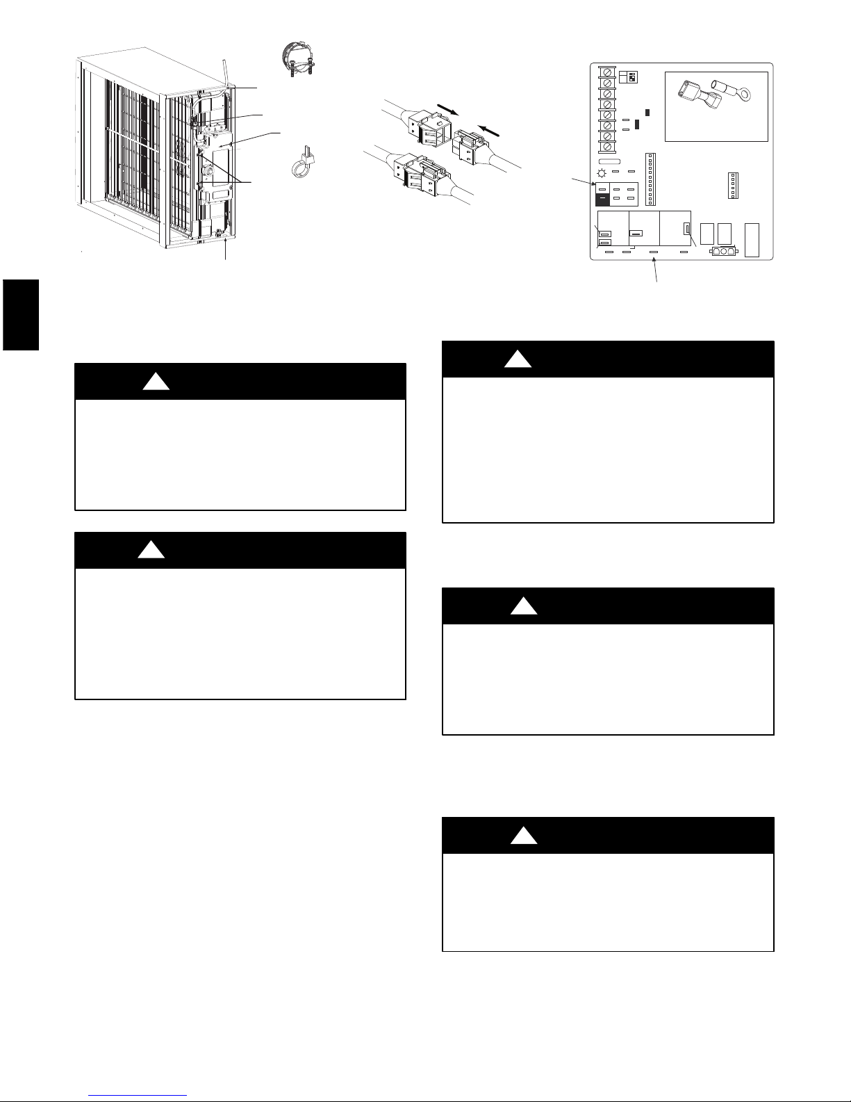
SDoor is not closed. A magnet in the door is used
to activate safety reed switches in the power
supply when the door is installed.
SThe door magnet is missing or has fallen out. SRe-cement loose door magnet with a suitable
adhesive.
SThe door safety reed switches may be defective.
SIf the unit switch is on and 115 Volt power is
available through the service cord, a door
magnet moved in close proximity of the power
supply will cause the reed switches to audibly
click and the power supply will turn on.
SFurnace blower is not operating. Power will not
be supplied from the furnace control’s EAC
terminals unless the blower is running.
SMake sure the furnace blower is operating.
SBent pins or loose connection in the molex plug
of the service cord.
SReplace Service cord or replace entire power
supply / field enhancement module assembly if
required.
SThe power supply may be defective. SReplace entire power supply / field enhancement
module assembly.
SThe light pipe transferring the light from the
LED’s on the power supply to the door may be
broken.
SReplace access door.
2 Power Indicator light cycles on and off
intermittently.
SOverload condition activating the safety
circuitry S
SUnit is wet. (Water may be entering the unit from
a source such as condensate or dripping from a
frozen evaporator coil.)
SRemove the access door and the air purifier
cartridge. Power the unit then use a spare door
magnet or “service” magnet to activate the air
purifier power supply. Turn out the lights and
observe for arcing.
SGrounding paths in the unit are interrupted due
to breakage , corrosion or loose contact.
SMake sure all three grounding clips (FEM to
cabinet, safety screen to cabinet, cartridge to
cabinet on the leaving air side) are securely in
place and making clean contact.
SArcing to ground (such as unit cabinet ) is
occurring.
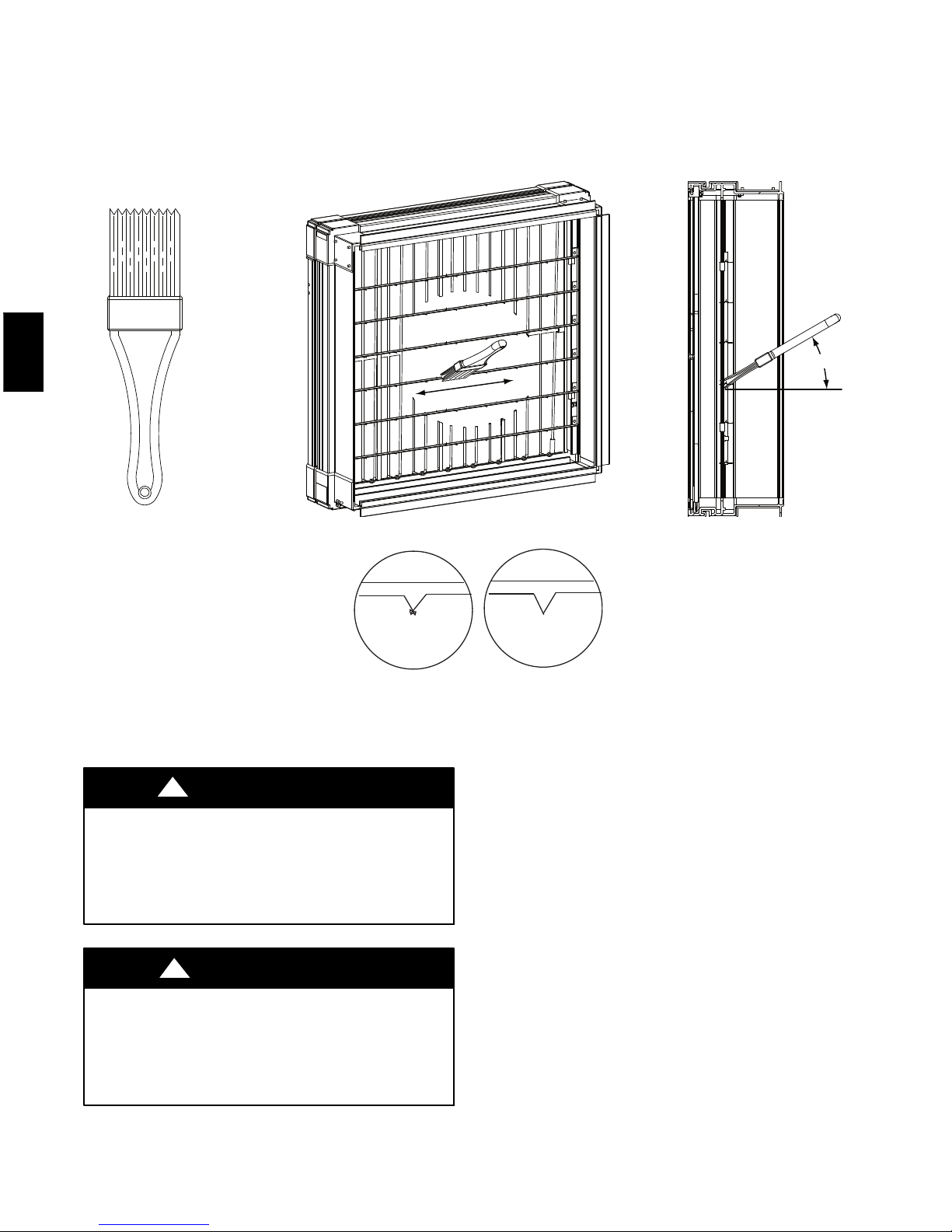
SMake sure the safety screen is clear and remove
debris.
SArcing to ground is occurring due to debris
lodged in the safety screen or across ionization
grid.
SMake sure the ionization grid is secured in place
with all four clips and centered in the FEM
housing.
SIonization grid is not centered or isloose and not
clipped in place, possibly touching the air
purifier cartridge or safety screen.
SVerify that the ionization grid is clean and intact.
SElectrode wire is loose and making contact with
the enhancement module wall.
SMake sure the field electrode wire is wound
through the spools on the enhancement module
with sufficient tension and tied to itself at the end
termination. If it is loose rewind and retie it.
SField electrode wire is damaged or nicked.
SIf the field electrode wire is damaged or nicked,
replace entire power supply / field enhancement
module assembly.
3 AirPurifier Cartridgehas smallsinge orchar
marks on the frame. SThe cartridge is installed backwards
STurn off the unit and remove the access panel.
SReplace the air purifier cartridge with Factory
Authorized Replacement Cartridge and ensure
airflow direction arrows are correct.
4 The wall control will not work.
SThe wire in the wall OR the wall control may be
defective.
SRemove the wall control and test it right beside
the unit using another shorter wire. If the wall
control works there, change the wire. If it does
not, change the wall control.
SThe wires may be in reverse position. SEnsure that the color coded wires have been
connected to their appropriate places.
SThewiresmaybebroken. SInspect every wire and replace any that are
damaged.
SThere may be a short-circuit. SWith the help of a multimeter, check for
continuity.
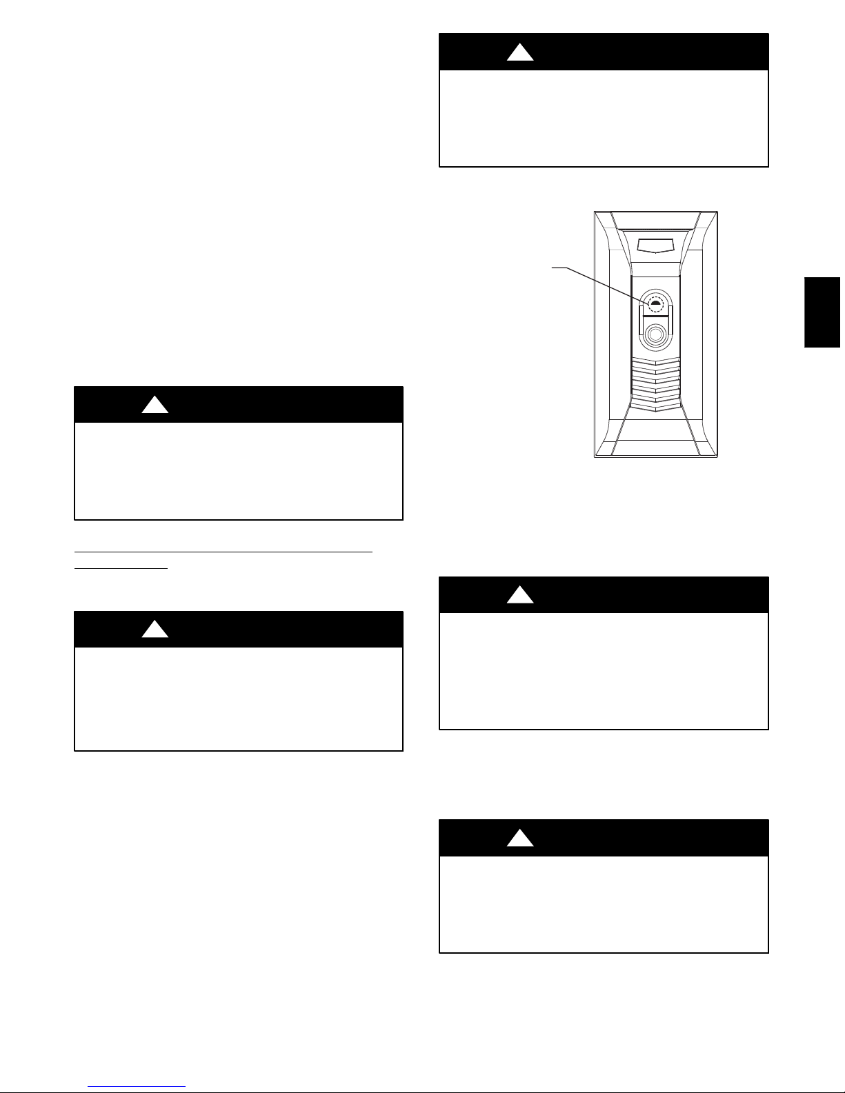
5 The 20-minute lighted push- button switch
doesn’t work OR its indicator light doesn’t
stay on.
SThe switch may be defective.
SJump the OL and OC terminals. If the unit
switches to high speed, then the wires are not the
problem. Replace the push-button.
SThe wires may be defective OR may not be
connected properly.
SEnsure that the color-coded wires have been
connected to their appropriate places.
GAPAA

10
SPECIFICATIONS AND DIMENSIONS
Table 2 – Specifications and Dimensions
SPECIFICATIONS GAPAAXBB1625 GAPAAXBB2025
Color Taupe Metallic Taupe Metallic
Cabinet Material 20 Ga. Powder Coated Steel 20 Ga. Powder Coated Steel
Electrical 115v/60 Hz (from furnace EAC terminals) 115v/60 Hz (from furnace EAC terminals)
Maximum Airflow (CFM) 1600 2000
Efficiency MERV 15 MERV 15
Replacement Cartridge GAPCCCAR1625 GAPCCCAR2025
Pressure Drop @ Maximum Airflow .25 InH20 .25 InH20
Dimensions GAPAAXBB1625 GAPAAXBB2025
A18---3/8---in (466.7mm) 21--- 7/8 --- in (555.6mm)
B15--- 1/8 --- in (384.1mm) 18---5/8 --- in (473.1mm)
C11--- 1/8 --- in (282.6mm) 11---1/8 --- in (282.6mm)
D17--- 1/2 --- in (444.5mm) 21--- in (533.4mm)
E22--1/8--in (562mm) 22--1/8--in (562mm)
F25--- 1/4 --- in (642.4mm) 25---1/4 --- in (642.4mm)
7/16" (11.1mm) (Typical Top & Bottom)*
1 3/16" (30.2mm)
1 3/16” (30.2mm)
1 3/16” (30.2mm)
1 15/16” (49.2mm)
A
CE
F
BD
A09021
Fig. 12 -- Dimensions
GAPAA

11
39004DP452
01/10
Limited Warranty for Air Purifier
FOR WARRANTY SERVICE OR REPAIR:
Contact the installer. You may find the installer’s name on the equipment or in your Owner’s Packet.
For help, contact: CAC / BDP, Consumer Relations, P.O. Box 4808, Syracuse, New York 13221, Phone 1-800-227-7437
PRODUCT REGISTRATION: You can register your product online at www.cac-bdp.com.
Model No. ____________________________________________
Unit Serial No. ________________________________________
Date of Installation _____________________________________
Installed by ___________________________________________
Name of Owner _______________________________________ Address of Installation __________________________________
CAC / BDP (hereinafter “Company”) warrants this product against failure due to defect in materials or workmanship under normal use and maintenance
as follows. All warranty periods begin on the date of original installation. If a part fails due to defect during the applicable warranty period Company
will provide a new or remanufactured part, at Company’s option, to replace the failed defective part at no charge for the part. Alternatively, and at its
option, the Company will allow a credit in the amount of the then factory selling price for a new equivalent part toward the retail purchase price of a new
Company product. Except as otherwise stated herein, those are Company’s exclusive obligations under this warranty for a product failure. This limited
warranty is subject to all provisions, conditions, limitations and exclusions listed below and on the reverse (if any) of this document.
OWNER-OCCUPIED, RESIDENTIAL APPLICATIONS
This warranty is to the original purchasing owner and is transferable only to the extent and as stated in the Warranty Conditions and below. The
warranty period in years, depending on the part and the claimant, is as shown in the chart below.
Limited Warranty (Years)
Product Original Owner Subsequent Owner
)5ro(**01)5ro(*01reifiruPriAAPAG
* If properly registered within 90 days, otherwise 5 years (except in California and Quebec and other jurisdictions that prohibit warranty benefits
conditioned on registration, registration is not required to obtain longer warranty periods). See Warranty Conditions below.
** If properly transferred within 90 days, otherwise 5 years. See Warranty Conditions below. In California and Quebec and other jurisdictions that
prohibit warranty benefits conditioned on registration, registration is not required for a transfer and all warranty periods for subsequent owners are
five years from original installation.
OTHER RESIDENTIAL APPLICATIONS (Apartments, Rental Properties, etc.)
The warranty period is five (5) years and is not transferable.
OTHER APPLICATIONS
This warranty is non-transferable. The warranty period is one (1) year on all such applications.
LEGAL REMEDIES - The owner must notify the Company in writing, by certified or registered letter to CAC / BDP, Warranty Claims, P.O. Box 4808,
Syracuse, New York 13221, of any defect or complaint with the product, stating the defect or complaint and a specific request for repair, replacement,
or other correction of the product under warranty, mailed at least thirty (30) days before pursuing any legal rights or remedies.
GAPAA

12
39004DP452
01/10
WARRANTY CONDITIONS:
1. To obtain the longer warranty periods as shown in the table under original owner, for the original purchaser, the product must be properly
registered at www.cac-bdp.com within ninety (90) days of original installation. In jurisdictions where warranty terms conditioned on
registration are prohibited by law, registration is not required and the longer warranty period shown will be apply.
2. Where a product is installed in a newly constructed home, the date of installation is the date the homeowner purchased the home from the
builder.
3. If the date of original installation cannot be verified, then the warranty period begins ninety (90) days from the date of product manufacture (as
indicated by the model and serial number). Proof of purchase may be required at time of service.
4. The remainder of the first five years of warranty is freely transferable without registration. To obtain a transfer of the longer warranty periods
as shown in the table under subsequent owner, a subsequent owner must register the transfer at www.cac-bdp.com within 90 days of the
change in ownership and payment of a transfer fee. Not applicable in all jurisdictions. See website for details.
5. Product must be installed properly and by a licensed HVAC technician.
6. The warranty applies only to products remaining in their original installation location.
7. Installation, use, care, and maintenance must be normal and in accordance with instructions contained in the Installation Instructions, Owner’s
Manual and Company’s service information.
8. Defective parts must be returned to the distributor through a registered servicing dealer for credit.
LIMITATIONS OF WARRANTIES: ALL IMPLIED WARRANTIES AND/OR CONDITIONS (INCLUDING IMPLIED WARRANTIES OR
CONDITIONS OF MERCHANTABILITY AND FITNESS FOR A PARTICULAR USE OR PURPOSE) ARE LIMITED TO THE DURATION OF THIS
LIMITED WARRANTY. SOME STATES OR PROVINCES DO NOT ALLOW LIMITATIONS ON HOW LONG AN IMPLIED WARRANTY OR
CONDITION LASTS, SO THE ABOVE MAY NOT APPLY TO YOU. THE EXPRESS WARRANTIES MADE IN THIS WARRANTY ARE
EXCLUSIVE AND MAY NOT BE ALTERED, ENLARGED, OR CHANGED BY ANY DISTRIBUTOR, DEALER, OR OTHER PERSON,
WHATSOEVER.
THIS WARRANTY DOES NOT COVER:
1. Labor or other costs incurred for diagnosing, repairing, removing, installing, shipping, servicing or handling of either defective parts, or
replacement parts, or new units.
2. Any product purchased over the Internet.
3. Normal maintenance as outlined in the installation and servicing instructions or Owner’s Manual, including filter cleaning and/or replacement
and lubrication.
4. Failure, damage or repairs from faulty installation, misapplication, abuse, improper servicing, unauthorized alteration or improper operation.
5. Failure to start due to voltage conditions, blown fuses, open circuit breakers, or damages due to the inadequacy or interruption of electrical
service.
6. Failure or damage due to floods, winds, fires, lightning, accidents, corrosive environments (rust, etc) or other conditions beyond the control of
Company.
7. Parts not supplied or designated by Company, or damages resulting from their use.
8. Products installed outside the U.S.A. or its territories and Canada.
9. Electricity or fuel costs, or increases in electricity or fuel costs from any reason whatsoever, including additional or unusual use of
supplemental electric heat.
10. Any cost to replace, refill or dispose of refrigerant, including the cost of refrigerant.
11. ANY SPECIAL, INDIRECT OR CONSEQUENTIAL PROPERTY OR COMMERCIAL DAMAGE OF ANY NATURE WHATSOEVER. Some
states or provinces do not allow the exclusion of incidental or consequential damages, so the above limitation may not apply to you.
This Warranty gives you specific legal rights, and you may also have other rights which vary from state to state or province to province.
Manufacturer reserves the right to discontinue, or change at any time, specifications or designs without notice and without incurring obligations.
E2010 Bryant Heating & Cooling Systems D7310 W. Morris St. DIndianapolis, IN 46231 Printed in China Edition Date: 10/10
Replaces: IIGAPAA --- 05
Catalog No. IIGAP
A
A
--- 0 6
GAPAA
This manual suits for next models
3
Table of contents
Other Bryant Air Cleaner manuals