Other manuals for 907
2
Table of contents
Other Bryant Air Cleaner manuals
Bryant
Bryant MACA User manual
Bryant 1625 User manual
Bryant GAPAB User manual
Bryant AIRT PURIFIER Manual
Bryant 901KAX Dimensions and installation guide
Bryant EACA User manual
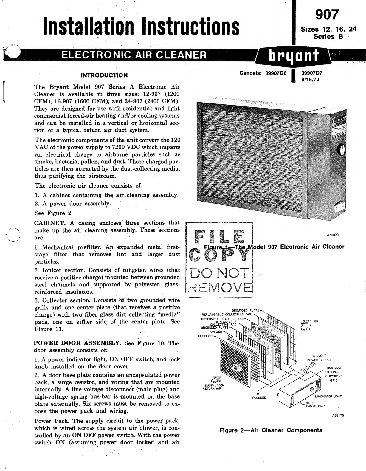
Bryant 907 Operation manual
Bryant 907 User manual
Bryant AIRA Planning guide
IKEA
IKEA UPPÅTVIND quick start guide
Nash
Nash AP-1 PureSmart instruction manual
LG
LG PH-U450 Series owner's manual
DeLonghi
DeLonghi DDSX 220WFA manual
Mitsubishi Electric
Mitsubishi Electric MA-E85R-E instruction manual
Sharp
Sharp FU-40SE Operation manual
Philips
Philips AC2721 user manual
TruSens
TruSens Z-2000 manual
Motorola
Motorola MBP87SN quick start guide
Beko
Beko ATP 7100I instruction manual
Carrier
Carrier INFINITY 1620 installation instructions
AtmosAir
AtmosAir P2002 user guide
Winix
Winix NK300 Use & care guide
Friedrich
Friedrich C-90A Service information
Surgically Clean Air
Surgically Clean Air JADE2.0 Operation manual
Base aire
Base aire 555 Pro Installation & operation manual
Champion
Champion CP25 instructions
vollara
vollara Air & Surface Pro+ manual