bSeen X E-bike User manual

X e-bike Owner’s
Manual
INTRODUCTION
Thank you for purchasing our bSeen product.
bSeen is an indicator light kit developed for electric scooters, electric
bicycles and any other vehicle that lacks of indicators, and light warning
systems.
Sold as a “do it yourself” kit, bSeen is a powerful and reliable system,
based on the latest technologies.
At the heart of the system, a micro-controller was programmed for the
most basic tasks, such as right and left turn, and other functions such as
hazard warning lights, horn and headlight control.
bSeen LED units are extremely bright, and can be seen during the day.
LED units are manufactured in-house and carefully inspected to ensure
their waterproof properties.
bSeen handlebar switch unit is easy to operate, with all controls you need
to control your indicator system.!
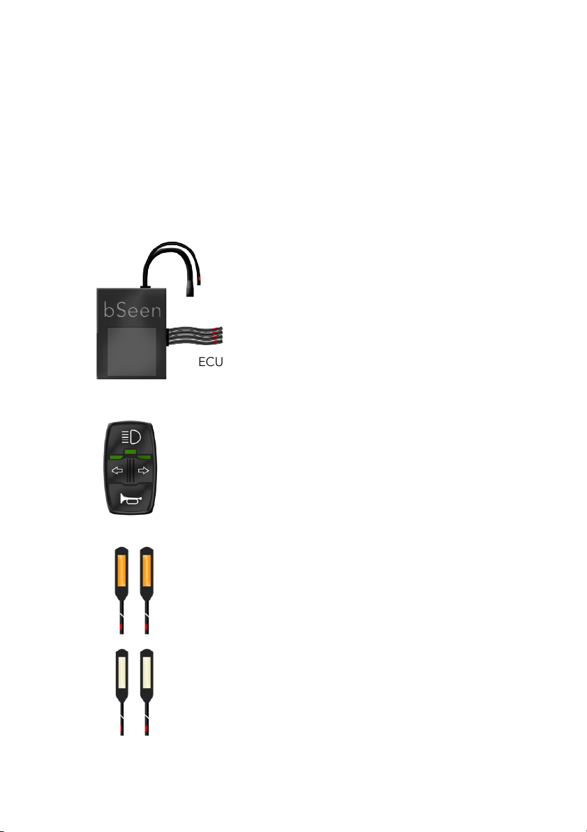
BOX CONTENTS
Inside your bSeen kit box you will find:
1 x ECU (Electronic Control Unit)
1 x Handlebar Control Unit
4 x LED units with cable tail
1 x Power lead
12 x Heat shrink sleeves
ECU (Electronic Control Unit)
Handlebar Control Unit
Amber LED Units (rear)
White LED Units (front)

SYSTEM SPECIFICATIONS
ECU
LED units
Handlebar Control
System Functions!
• Input voltage: 18V - 78V DC
• Main board operating voltage: 9V DC
• Outputs voltage: 12V DC regulated
• Power consumption in standby mode: 14mA
• Heat resistant PVC box
• Dimensions: 50mm (L) x 40mm (W) x 33mm (H)
• Weight: 100g
• Maximum operating voltage: 12.7V
• Maximum output power: 2.1W
• Electronic circuit type: Chip on board
• Colour: Cool White (front units), Amber (rear
units)
• IP66 rated waterproof
• Dimensions: 55mm (L) x 15mm (W) x 3.5mm
(H)
• Headlight switch (ON/OFF), Left/Right turn
switch, horn switch.
• LED monitoring for headlight and turning
signals
• Headlight ON/OFF (headlight sold separately)
• Horn ON/OFF time limited to 1.5sec
consecutive buzz (horn sold separately)
• Left Turn
• Right Turn
• Hazard Lights
• Presence/Daytime Front Lights
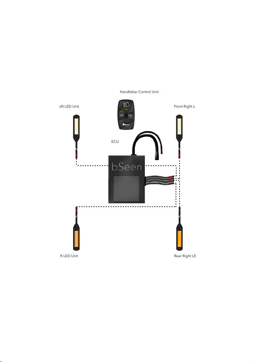
BASIC INSTALLATION DIAGRAM
!
Handlebar Control Unit
Front Right LED Unit
Front Left LED Unit
Rear Left LED Unit
Rear Right LED Unit
ECU

BSEEN ELEMENTS’ LOCATION!
Handlebar Control Unit
mounted on the left or right
side of the handlebar.
Front LED
indicators
mounted on
the fork
Rear LED
indicators
mounted on
the rear
frame/fork
ECU mounted - hidden
on the frame

INSTALLATION
bSeen X e-bike was designed to be fitted on your e-bike, and it uses your
bike’s battery power to operate.
PROCEED WITH CAUTION AND READ CAREFULLY
The installation of the bSeen X kit requires electric skills, such as
soldering and stripping electrical wires.
If you’re not familiar with such proceedings, ask for support from your
bicycle dealer or from an automotive electrician expert.
Damage to the bSeen ECU, LED units and/or Handlebar Control Unit
due to faulty connections, short circuits or polarity inversions, will not be
covered by warranty.
Please keep in mind, modifications to your e-bike can void its warranty.
Make sure you read and understand your e-bike’ manufacturer warranty
terms, and proceed with bSeen’s kit installation with caution.
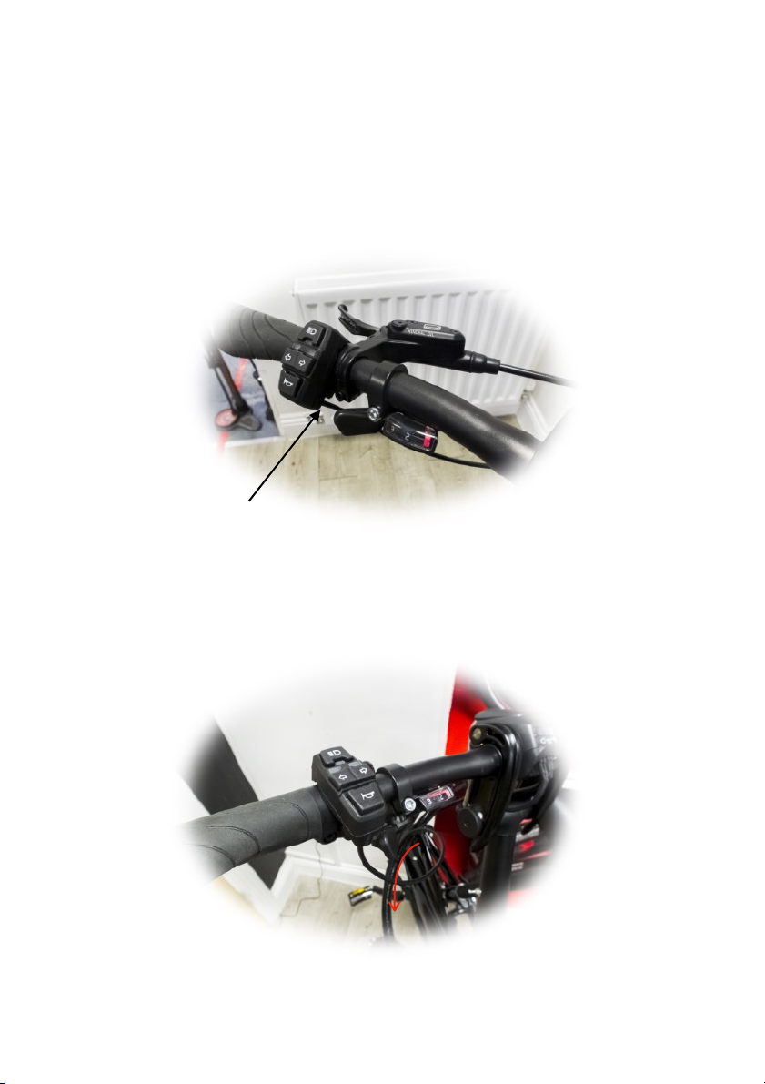
INSTALLATION - HANDLEBAR CONTROL UNIT
Remove your left or right handlebar grip, and once removed, install the
bSeen Handlebar Control Unit in place. Be sure to tighten the hexagonal
screw located at the back of the unit:
The Handlebar Control Unit is supplied with a 2 metres cable length and a
Higo connector. The cable runs along with the brake and gear line, to the
place where you decided to fit the ECU (bSeen Control Unit):
Tighten the hexagonal screw located on the back of the unit

INSTALLATION - REAR LED UNITS & CABLE MANAGEMENT
Rear LED units (indicators) can be fitted on both sides of the rear frame/
forks.
Each LED unit is supplied with a 3M VHB double tape pad, designed for
automotive industry and resistant to all kinds of weather conditions.
Find the best place to fit each indicator. These should be facing the traffic
behind your e-bike, so your turning intentions can be seen by other road
users.
Peel the double tape on the back of the LED, and stick the LED unit in
place. The bonding process will take up to 24 hours to complete. You can,
however, use the e-bike normally, after finishing your installation. This
won’t interfere with the bonding process.
Left indicator
Right indicator
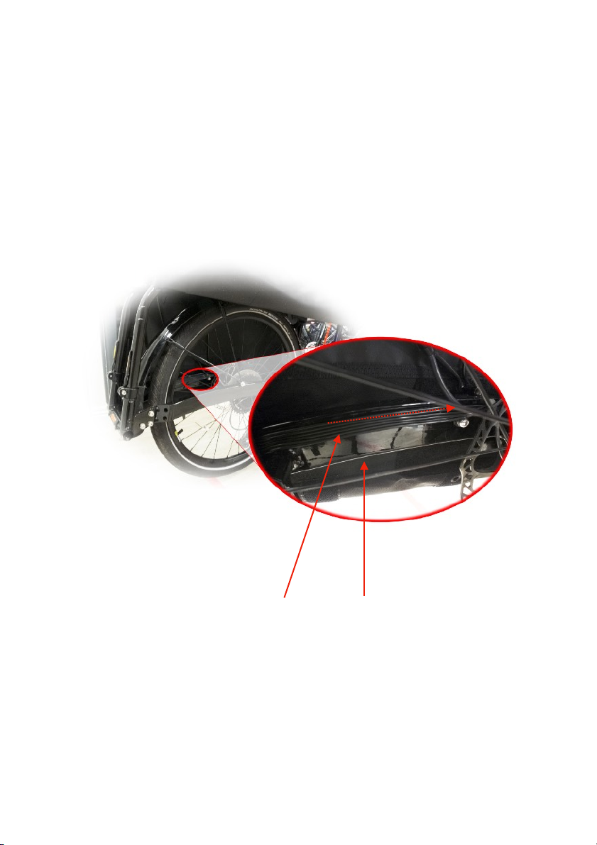
Run the LED units’ cables through the e-bike’s frame to the place where
you decided to fit the ECU.
In the picture bellow, the cables are fixed with the same 3M VHB double
tape on the interior of the the chain stays, and then it was used cable ties
to secure the cable to through the rear brake line.
LED units’ cables
Chain Stay
Table of contents
Other bSeen Control Unit manuals

Popular Control Unit manuals by other brands

Festo
Festo Compact Performance CP-FB6-E Brief description

Elo TouchSystems
Elo TouchSystems DMS-SA19P-EXTME Quick installation guide

JS Automation
JS Automation MPC3034A user manual

JAUDT
JAUDT SW GII 6406 Series Translation of the original operating instructions

Spektrum
Spektrum Air Module System manual

BOC Edwards
BOC Edwards Q Series instruction manual

KHADAS
KHADAS BT Magic quick start

Etherma
Etherma eNEXHO-IL Assembly and operating instructions

PMFoundations
PMFoundations Attenuverter Assembly guide

GEA
GEA VARIVENT Operating instruction

Walther Systemtechnik
Walther Systemtechnik VMS-05 Assembly instructions

Altronix
Altronix LINQ8PD Installation and programming manual


