Helios KWL-CO2 User manual
CO2-Fühler für easyControls
CO2Sensor for easyControls
KWL-CO2
zur Erfassung der CO2-Konzentration in der
Raumluft
for measuring the CO2concentration in room air
Helios Ventilatoren
BEDIENUNGSANLEITUNG
OPERATING INSTRUCTIONS EN
DE

1.0 Wichtige Informationen
Zur Sicherstellung einer einwandfreien Funktion und zur eigenen Sicherheit sind alle
nachstehenden Vorschriften genau durchzulesen und zu beachten. Nationale einschlägi-
gen Normen, Sicherheitsbestimmungen und Vorschriften (z.B. DIN EN VDE 0100) sowie
die TAB des EVUs sind unbedingt zu beachten und anzuwenden.
Die Bedienungsanleitung als Referenz am Gerät aufbewahren. Nach der Endmontage
muss dem Betreiber (Mieter/Eigentümer) das Dokument ausgehändigt werden.
1.1 Warn- und Sicherheitshinweise
Nebenstehendes Symbol ist ein sicherheitstechnischer Warnhinweis. Alle Sicher-
heitsvorschriften bzw. Symbole müssen unbedingt beachtet werden, damit jeg-
liche Gefahrensituation vermieden wird.
1.2 Garantieansprüche – Haftungsausschluss
Wenn die nachfolgenden Ausführungen nicht beachtet werden, entfällt unsere Gewähr-
leistung. Gleiches gilt für Haftungsansprüche an den Hersteller. Der Gebrauch von Zu-
behörteilen, die nicht von Helios empfohlen oder angeboten werden, ist nicht statthaft.
Eventuell auftretende Schäden unterliegen nicht der Gewährleistung.
1.3 Vorschriften – Richtlinien
Bei ordnungsgemäßer Installation und bestimmungsgemäßem Betrieb entspricht das
Produkt den zum Zeitpunkt seiner Herstellung gültigen Vorschriften und EG-Richtlinien.
1.4 Sendungsannahme
Die Lieferung enthält den
CO2
-Fühler KWL-
CO2inkl. Verbindungskabel
. Die Sendung ist
sofort bei Anlieferung auf Beschädigungen und Typenrichtigkeit zu prüfen. Falls Schäden
vorliegen umgehend Schadensmeldung unter Hinzuziehung des Transportunternehmens
veranlassen. Bei nicht fristgerechter Reklamation gehen evtl. Ansprüche verloren.
1.5 Einlagerung
Bei Einlagerung über einen längeren Zeitraum sind zur Verhinderung schädlicher Ein-
wirkungen folgende Maßnahmen zu treffen:
Schutz durch trockene, luft- und staubdichte Verpackung (Kunststoffbeutel mit Trocken-
mittel und Feuchtigkeitsindikatoren). Der Lagerort muss erschütterungsfrei, wasser-
geschützt und frei von übermäßigen Temperaturschwankungen sein. Schäden, deren
Ursprung in unsachgemäßem Transport, unsachgemäßer Einlagerung oder Inbetrieb-
nahme liegen, sind nachweisbar und unterliegen nicht der Gewährleistung.
1.6 Bestimmungsgemäße Verwendung
Der CO2-Fühler dient zur Erfassung der
CO2-Konzentration in der
Raumluft.
Der
CO2
-Fühler
KWL-
CO2
kann an alle KWL-Kompaktgeräte mit easyControls Steuerung (Helios-Pro-
gramm) angeschlossen werden (bis zu max. 8 Stück).
Ein bestimmungsfremder Einsatz ist nicht zulässig!
2.0 Technische Daten
KWL-
CO2
Maße (B x H x T) mm 94 x 96 x 30
Spannungsversorgung 20 - 28 V DC (±10 %) oder
16,5 - 24 V AC (-10 %)
Stromaufnahme 40 mA bei 24 V DC (Ruhe)
173 mA bei 24 V DC (Messimpuls)
Steuerleitung SL 4/3 (3 m lang)
Anschlussmöglichkeit bis zu 8 Stück
KAPITEL 1
ALLGEMEINE
HINWEISE
m
ACHTUNG m
KAPITEL 2
SCHALTPLAN
DE
CO2-Fühler KWL-CO2 für easyControls
Bedienungsanleitung
1

CO2-Fühler KWL-CO2 für easyControls
Bedienungsanleitung
2
DE
Umgebungstemperatur 0 - 40 °C
Messbereich CO2400-2000 ppm
Belastbarkeit Analogausgänge max. 20 mA
Kabelquerschnitt Federzugklemme Ø 0,75 mm mit Aderendhülse
Ø 1,5 mm ohne Aderendhülse
3.0 Elektrischer Anschluss
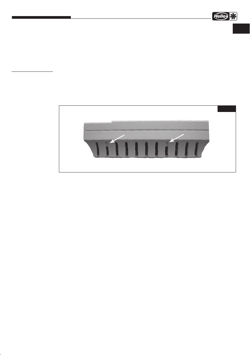
1. Gehäuse öffnen
Schnapphaken nach innen drücken (s. Abb. 1).
Im Deckel des Gehäuses befindet sich die Elektronik des CO2-Fühlers.
Beim späteren Zusammenbau die Schnapphaken auf einer Seite des Gehäuseunterteils ein-
haken und das Gehäuse einrasten.
2. Anschluss
2.1 Anschluss einer externen Spannungsversorgung
– Steckbrücke auf Ext. setzen (s. Schaltplan).
– Anschluss über die Push-Klemmen (24 V~) an eine geeignete Spannungsversorgung.
Zu Beachten:
Spannungsbereich DC ±10% 20 - 28 V
Spannungsbereich AC -10% 16,5 - 24 V
Nennstrom bei 24 V DC im Ruhezustand 40 mA
Nennstrom bei 24 V DC bei Messimpuls 173 mA
Die angegebenen Spannungsbereiche dürfen nicht über oder unterschritten werden. Die
Polung (+/-) ist beliebig.
2.2 Anschluss an Helios BUS
– Anschluss gemäß Schaltplan.
Adressierung
Sind mehrere CO2-Fühler angeschlossen, muss die Adressierung angepasst werden. Es
darf keine Doppelvergabe der Adressen für die Fühler 1-8 erfolgen! (s. Dip-Schalter Tabelle;
Schaltplan).
KAPITEL 3
ELEKTRISCHER
ANSCHLUSS
Abb.1

CO2-Fühler KWL-CO2 für easyControls
Bedienungsanleitung
3
3. Verwendung der Analogausgänge
Anschluss des CO2-Fühlers KWL-
CO2
an ein Lüftungsgerät (KWL Gerät, Ventilator etc.), das
mit einem Analogeingang (0-10 V) ausgestattet ist. Polung beachten!
Zu Beachten:
Anschluss KWL-
CO2
A1 CO2 400-2000 ppm 1,7-10 V max. 20 mA
GND GND
Bevor ein Messwert ausgegeben wird benötigt der KWL-
CO2
Fühler eine Initialisierungszeit
von etwa 2 Minuten.
DE

CO2-Fühler KWL-CO2 für easyControls
Bedienungsanleitung
4
KWL-CO
Art.Nr. 4272
2
A1
GND
A2
GND
20-28V DC
16,5-24V AC
+ -
1,7-10V=
ppm
400-2000
85314 001 SS-1073 04.05.18
max. 20 mA
JP2
BUS
extern
JP1
RJ-10
14
RJ-10
14
2)
DIP
1
off
on
2 3 4
KWL-SL Leitungen bei Unterputz Verlegung min. in M25 Rohr verlegen.
KWL-SL 4/.. x 0,12mm² max. Länge siehe SS-1077
KWL EC ... easyControls
Hinweise zur Verbindungsleitung:
KWL-SL 4/3 (3 m im Lieferumfang inkl. RJ10-Stecker)
(5 m- SL4/5, 10 m- SL4/10, 20 m- SL4/20)
14
KWL-
Komponenten KWL-EC ...
14 14
Helios-BUS
Gesamtzahl der
Komponenten begrenzt.
Maximaler Helios
BUS-Strom = 0,9A
Zusätzliche externe
Einspeisung siehe in
entsprechenden
Detailplänen.
Weitere Hinweise im
Komponenten - BUS- Plan
SS-1077
max. 8 Stück
Nr. 2 Nr. 8
JP1
14 14
KWL-CO
Art.Nr. 4272
2
Nr. 1
JP1
14 14
DIP
1
off
on
2 3 4
DIP
1
off
on
2 3 4
KWL-CO
Art.Nr. 4272
2
externer
Kontakt
Potential 3 V
Übersicht easyControls SS-1042-1045
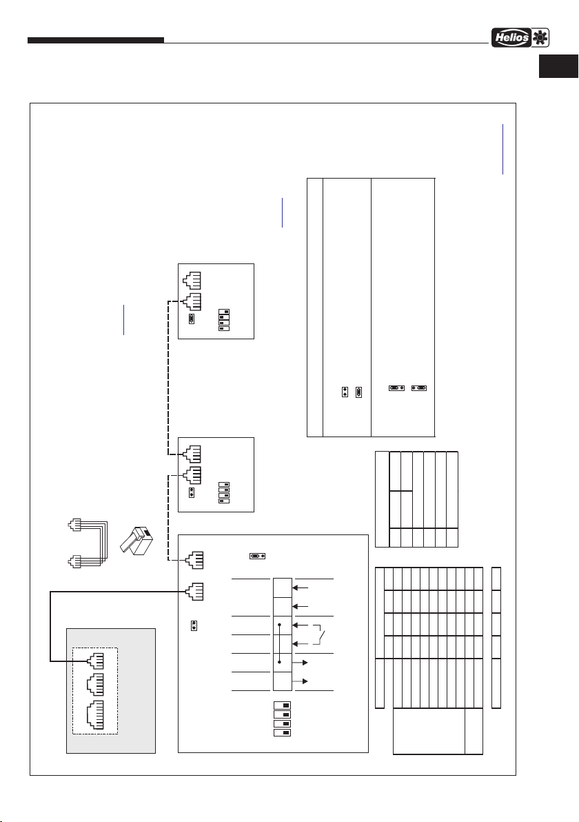
1) Standard ist die Versorung über den BUS.
Bei externer Versorgung Jumper 2 umstecken.
JP2 Externe 24 VDC Spannungsversorgung
unten
oben 24 VDC über BUS-Stecker
24 VDC Spannungsversorung extern
JP-Jumper Funktionen:
JP1 Endwiderstand
offen
gesteckt
ohne Endwiderstand, nicht letzter BUS-Teilnehmer
Endwiderstand 120 Ohm aktiv, letzter Teilnehmer im BUS
RJ-10 RJ-10
PI N Digital Digital
1
2
3
4
+24,5 V / I max 0,9 A
BUS A
BUS B
GND
RJ-Belegung:
2) Die Sensor Messwerte werden auf dem BUS und
den Analogausgängen ausgegeben.
Messwert zum Analogwert linear.
0 = off, 1 = on
1234
1 0 0 0 ----
2 1 0 0 ----
3 0 1 0 ----
4 1 1 0 ----
5 0 0 1 ----
6 1 0 1 ----
7 0 1 1 ----
8 1 1 1 ----
inaktiv ---- ---- ---- 0
aktiv ---- ---- ---- 1
Auslieferung 0 0 0 0
DIP-Schalter
Adresse
externer
Kontakt
18 16 14
LAN Analog
RJ-45 RJ-12 RJ-10
1)
24V~
4. Schaltplan SS-1073
DE

1.0 Important information
In order to ensure complete and effective operation and for your own safety, all of the
following instructions should be read carefully and observed. The relevant national stan-
dards, safety regulations and instructions (e.g. DIN EN VDE 0100) as well as the technical
connection conditions of the energy supply company must be observed and applied.
Keep the operating instructions close to the unit for easy reference. After the final assem-
bly, the document must be issued to the operator (tenant/owner).
1.1 Warning and safety instructions
The adjacent symbol is a safety-relevant warning symbol. All safety regulations
and/or symbols must be absolutely adhered to, so that any dangerous situation
is avoided.
1.2 Warranty claims – Exclusion of liability
Our warranty shall not apply if the following instructions are not observed. The same
applies for liability claims against the manufacturer. The use of accessories, which are
not recommended or offered by Helios, is not permitted. Any damage that may occur is
not liable for warranty.
1.3 Regulations - Guidelines
If the product is installed correctly and used to its intended purpose, it conforms to all
applicable regulations and EC guidelines at its date of manufacture.
1.4 Receipt
The delivery contains the
CO2
Sensor KWL-
CO2incl. connection cable
. Please check
delivery immediately on receipt for accuracy and damage. If damaged, please notify
the carrier immediately. In case of delayed notification, any possible claim may be void.
1.5 Storage
When storing for a prolonged time, the following steps are to be taken to avoid damaging
influences:
Protection by dry, air-dustproof packing (plastic bags with drying agent and moisture
indicators). The storage place must be waterproof, vibration-free and free of temperature
variations. Damages due to improper transportation, storage or commissioning must be
verified and are not liable for warranty.
1.6 Intended use
The CO2sensor serves to measure the
CO2concentration in room air
.
The
CO2
sensor KWL-
CO2
can be connected to all KWL compact units with the easyControls control system
(Helios range) (up to max. 8 units).
Any other use than the intended use is prohibited!
2.0 Technical data
KWL-
CO2
Dimensions (W x H x D) mm 94 x 96 x 30
Power supply 20 - 28 V DC (±10 %) or
16.5 - 24 V AC (-10 %)
Power consumption 40 mA at 24 V DC (idle)
173 mA at 24 V DC (measuring impulse)
Control line SL 4/3 (3 m long)
Connection options up to 8 units
CHAPTER 1
GENERAL
INFORMATION
m
ATTENTION m
CHAPTER 2
WIRING DIAGRAM
EN
CO2Sensor KWL-CO2 for easyControls
Operating Instructions
1
CO2Sensor KWL-CO2 for easyControls
Operating Instructions
2
EN
Ambient temperature 0 - 40 °C
Measuring range CO2400-2000 ppm
Load capacity Analogue outputs max. 20 mA
Cable cross-section spring terminal Ø 0.75 mm with wire end ferrule
Ø 1.5 mm without wire end ferrule
3.0 Electrical connection
1. Open housing
Press snap-in hooks inwards (see Fig. 1).
The CO2sensor electronics are located in the lid of the housing.
Hook the snap-in hooks to one side of the housing base and snap the housing in for sub-
sequent assembly.
2. Connection
2.1 Connection of an external power supply
– Set plug-in jumper to Ext. (see wiring diagram).
– Connection via the push-in terminals (24 V~) to a suitable power supply.
Please note:
Voltage range DC ±10% 20 - 28 V
voltage range AC -10% 16.5 - 24 V
Rated current at 24 V DC in idle state 40 mA
Rated current at 24 V DC with meas. imp. 173 mA
The specified voltage range must not be exceeded or fallen below. The polarity (+/-) is ar-
bitrary.
2.2 Connection to Helios BUS
– Connection according to wiring diagram.
Addressing
If multiple CO2sensors are connected, the addressing must be adjusted. There must be no
double address allocations for sensors 1-8! (see DIP switch table; wiring diagram).
CHAPTER 3
ELECTRICAL
CONNECTION
Fig.1

CO2 Sensor KWL-CO2 for easyControls
Operating Instructions
3
3. Use of analogue outputs
Connection of CO2sensor KWL-
CO2
to a ventilation unit (KWL unit, fan etc.), which is equip-
ped with an analogue input (0-10 V). Note polarity!
Please note:
Connection KWL-
CO2
A1 CO2 400-2000 ppm 1,7-10 V max. 20 mA
GND GND
The KWL-
CO2
sensor needs an initialisation period of around 2 minutes before a measure-
ment value is issued.
EN
CO2 Sensor KWL-CO2 for easyControls
Operating Instructions
4
KWL-CO
Ref.no. 4272
2
A1
GND
A2
GND
15 to
1)
28 VDC
+-
1,7-10V=
ppm
400-2000
85314 001 SS-1073 10.06.16
max. 20 mA
JP2
BUS
ext.
JP1
RJ-10
14
RJ-10
14
2)
DIP
1
off
on
234
KWL-SL cables for flush-mounted installation min. install in M25 duct.
KWL-SL 4/.. x 0.12mm² max. length see SS-1077
KWL EC ... easyControls
Connection cable information:
KWL-SL 4/3 (3 m incl. in delivery. RJ10 plug)
(5 m- SL4/5, 10 m- SL4/10, 20 m- SL4/20)
14
KWL-
Components KWL-EC ...
14 14
Helios-BUS
Total number of
components limited.
Maximum Helios
BUS current = 0.9A
Additional external
supply see in
corresponding
detailed plans.
Further information in
components- BUS- Plan
SS-1077
max. 8 units
No. 2 No. 8
JP1
14 14
KWL-CO
Ref.no. 4272
2
No. 1
JP1
14 14
DIP
1
off
on
234
DIP
1
off
on
234
KWL-CO
Ref.no. 4272
2
external
contact
Potential 3 V
Overview easyControls SS-1042-1045
1) Standard power supply via the BUS.
Relocate Jumper 2 for external power supply.
JP2 External 24 VDC power supply
bottom
top 24 VDC via BUS plug
24 VDC external power supply
JP jumper functions:
JP1 Terminal resistance
open
bridged
no terminal resistance, non-last BUS user
Terminal resistance 120 Ohm active, last user in BUS
RJ-10 RJ-10
PI N Digital Digital
1
2
3
4
+24,5 V / I max 0 .9 A
BU S A
BU S B
GND
RJ assignment:
2) The sensor measurements are sent to the BUS and
analogue outputs.
Measures value to analogue value linear.
0 = off, 1 = on
1234
1 0 0 0 ----
2 1 0 0 ----
3 0 1 0 ----
4 1 1 0 ----
5 0 0 1 ----
6 1 0 1 ----
7 0 1 1 ----
8 1 1 1 ----
inactive --- --- ---- 0
active --- --- ---- 1
Delivery 0 0 0 0
DIP switch
Address
external
contact
18 16 14
LAN Analog
RJ-45 RJ-12 RJ-10
4. Wiring diagram SS-1073
EN

CO2 Sensor KWL-CO2 for easyControls
Operating Instructions
5

CO2 Sensor KWL-CO2 for easyControls
Operating Instructions
6

Service und Information
DHELIOS Ventilatoren GmbH + Co KG · Lupfenstraße 8 · 78056 VS-Schwenningen FHELIOS Ventilateurs · Le Carré des Aviateurs · 157 avenue Charles Floquet · 93155 Le Blanc Mesnil Cedex
CH HELIOS Ventilatoren AG · Steinackerstraße 36 · 8902 Urdorf GB HELIOS Ventilation Systems Ltd. · 5 Crown Gate · Wyncolls Road · Severalls Industrial Park ·
AHELIOS Ventilatoren · Postfach 854 · Siemensstraße 15 · 6023 Innsbruck Colchester · Essex · CO4 9HZ
www.heliosventilatoren.de
Als Referenz am Gerät griffbereit aufbewahren!
Please keep for reference with the unit! Druckschrift-Nr. 82 221-001/0518
Other manuals for KWL-CO2
2
Table of contents
Languages:
Other Helios Accessories manuals

Helios
Helios KWL-CO2 User manual

Helios
Helios AIR1/KWL-VOC 0-10V User manual

Helios
Helios Core User manual

Helios
Helios KWL-VOC User manual

Helios
Helios KWL-FTF User manual

Helios
Helios KWL-CO2 User manual

Helios
Helios LTA 40 User manual

Helios
Helios KWL-KDF User manual

Helios
Helios CO2 AP-A User manual

Helios
Helios 91739 User manual


