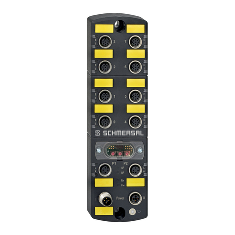
BST EKR 1500PDP Operational manual

Web guiding system EKR 1500PDP EDV-No.: MD.088.01.01
with analogue sensors and CCD 2004 H Issue: 14.08.2000
BST-Web Guiding System
EKR 1500PDP
with integrated Profibus DP module,
analogue sensors and CCD 2004
Translation of the Original
Operating Manual
BST Servo-Technik GmbH
Heidsieker Heide 53
D-33739 Bielefeld, Germany
Telephone: ++49 (0) 5206/999 – 0
Fax: ++49 (0) 5206/999 – 999

Web guiding system EKR 1500PDP EDV-No.:MD.088.01.01
with analogue sensors and CCD 2004 H Date: 14.08.00
Definition of the symbols in this manual
Warning notes
In this manual symbols are used to mark very important
statements.
Attention!
Warning notes of this type must be followed to protect
the operator from physical injuries caused by
mechanical influences.
Caution!
Warning notes of this type must be followed
absolutely to protect the operator from highly
dangerous injuries caused electrical voltage.
Notice
This symbol marks useful application tips which help
the operator to use all functions optimally.
Operation of the keys
In this manual the operation of the keys is represented by the
following symbols:
Press key.
Key combination, keys have to be
pressed simultaneously.
Press keys in the specified order.
Operating states
of the LED´s
Some keys on the front panel of the external keyboard EKR 3000
Commander are equipped with LEDs (light-emitting diodes).
The different operating states of the LEDs are represented as
follows:
LED off
LED constantly lighted = activated phase
LED blinking
1) 2)
+
!

Contents 0
Web guiding system EKR 1500PDP EDV-No.:MD.088.01.01 Chapter: 0
with analogue sensors and CCD 2004 H Date: 14.08.00 Page: 1/2
Contents
Table of contents
1 Description 1-5
1.1 General 1-5
1.2 Connectable components 1-5
1.3 Operating elements 1-5
1.4 Signification of the keys on the front panel 2-5
1.5 Signification of the LED´s on the front panel 3-5
1.6 Position of the Profibus-DP board in the terminal cover 4-5
1.7 Safety instructions 4-5
1.8 Emissions 5-5
2 Technical data 1-1
3 Transportation/Storage 1-1
4 Mounting 1-3
4.1 Location requirements 1-3
4.2 Mounting plan 1-3
4.3 Installation 2-3
4.4 Installation of EMC-wiring 3-3
5 Start-up 1-23
5.1 Requirements for start-up 1-23
5.1.1 Profibus-DP module 1-23
5.1.2 Programmable logical control (PLC) 5-23
5.1.3 EKR 1500PDP 5-23
5.2 Sensor adjustment 8-23
5.3 Start-up 9-23
5.4 Basic SET UP 9-23
5.5 Determine desired sense of rotation 11-23
for manual operation
5.6 Start-up of automatic operation with sensor 1 11-23
(and possibly sensor 2)
5.7 Electric powered actuators 16-23
5.8 Hydraulic powered actuators 17-23
5.9 Preparation for BS 100 and ZT 6008 18-23
5.10 Start-up of camera CCD 2004 19-23
6 Operation 1-12
6.1 EKR 1500PDP 1-12
6.2 Test of material contrast and scanning 4-12
with optical sensors
6.3 Change of web material 5-12
6.4 Watchdog function 9-12
6.5 Operation of the Profibus DP module 11-12
7 Remote control 1-1
8 Trouble shooting 1-1
9 Maintenance 1-1
10 De-commissioning 1-1

Contents 0
Web guiding system EKR 1500PDP EDV-No.:MD.088.01.01 Chapter: 0
with analogue sensors and CCD 2004 H Date: 14.08.00 Page: 2/2
A Appendix
Annex A1: Connecting plan
Annex A2: General plan
Annex A3: Types of Profibus-DP cables
Software version 1xx-xx:
Annex 1: BST standard assignment
Annex 2: Signification of channel assignment

Description 1
Web guiding system EKR 1500PDP EDV-No.:MD.088.01.01 Chapter: 1
with analogue sensors and CCD 2004 H Date: 14.08.00 Page: 1/7
Please follow the instruction of start-up,
maintenance and installation as described
in the operating instruction!
1 Description
1.1 General
The EKR 1500PDP system is a microprocessor-controlled web
guiding system. This guiding system may be used for:
·web edge guiding (right or left)
·center-line guiding
·guiding on continuous or interrupted printed lines
·guiding on continuous or interrupted printed edges
·guiding to a printed line or edge with automatic change-over to
edge or center-line guiding when the printed line/edge is
interrupted or has got lost (for example, in case of a web splice)
The system includes a Profibus DP module for instantaneous
communication with locally peripheral equipment.
Please contact the producer for any different application.
The system has PLC-compatible inputs and also an ‘OK-relay’ with
NO and NC contact.
1.2 Connectable
components
The general plan (annex A2) indicates the connectable edge
sensors and components to the EKR 3000PDP Controller.
1.3 Operating elements
* The amplifier includes all necessary operating elements.
Option: - Remote control by external signals, sensors or keys
Attention! External keys will interlock the reverse
function keys at the amplifier.
- If system locking is desired (e. g., in case of machine stop), this
can be achieved by means of external contacts or signals from
the PLC.
* Connection of components via separated terminal compartment.
Advantage: quick and easy accessibility to the terminal parts.
* Indication of web edge position by two LED arrays
Advantage: - simple control of the web edge within the
measuring range of sensors
- simple adjustment of the desired position of the
web or edge sensors
- variations of web width exceeding via the
admissible value
!

Description 1
Web guiding system EKR 1500PDP EDV-No.:MD.088.01.01 Chapter: 1
with analogue sensors and CCD 2004 H Date: 14.08.00 Page: 2/7
1.4 Signification of the keys on the front panel
Key / combination of keys Function
Automatic guiding
Manual positioning
Servo-center of the guiding device
1) 2) Manual shifting
1) 2) Shifting of guiding point to the left
1) 2) 3) Increase of gain
1) 2) Manual shifting
1) 2) Shifting of guiding point to the right
1) 2) 3) Decrease of gain
1) 2) 3) Increase of S-C transducer gain
1) 2) 3) Decrease of S-C transducer gain

Description 1
Web guiding system EKR 1500PDP EDV-No.:MD.088.01.01 Chapter: 1
with analogue sensors and CCD 2004 H Date: 14.08.00 Page: 3/7
Key / combination of keys Function
1) 2)
Release of gain with the keys
and
1) and/or 2) SET UP when changing
the material
Storing of the adjustments
and end of SET UP functions
Guiding to the left web edge
Guiding to the right web edge
Center-line guiding
Guiding to a printed line or edge
(also interrupted) with CCD 2004
Watchdog
Automatic change-over to edge
guiding when the printed line or
edge is interrupted or has got lost.
When the printed line or edge
reappears, the guiding function is
taken over automatically by CCD
2004.
1.5 Signification of the LED’s on the front panel
The LED’s on the keys indicate the switched on function.
·The blinking of the LED’s on the keys AUTO, MAN, S-C and
SET UP or of the LED-arrays 10 – 14 and/or 15 – 19 indicate a
fault message.
Simultaneously, the OK-relay is switched off (see chapter 8).
·LED-no. 10, 14, 15 and 19 (red) signalise the limits of the
measuring band of the edge sensors.
·LED-no. 12 and 17 (green) signalise the center of the
measuring band of the edge sensors.
·additional indications of the LEDs for gain and shifting of the
guiding point see points 5.10.3, 6.1.3, 6.2 and 6.3.
10 11 12 13 14 15 16 17 18 19
+

Description 1
Web guiding system EKR 1500PDP EDV-No.:MD.088.01.01 Chapter: 1
with analogue sensors and CCD 2004 H Date: 14.08.00 Page: 4/7
1.6 Position of the Profibus-DP board in the terminal cover
(rear view in the terminal cover)
1.7 Safety instructions
Installation of the BST equipment into the production machine
according to the relevant rules (EN 294, EN 349) and the specific
branch-oriented regulations for prevention of accidents, such as:
·Safety distances between BST equipment and customer´s
specification, e. g. machine walls, construction etc.
·Installation of connecting cables between controller and guiding
device and/or edge sensors stumble-free, nontension and well
anchored.
·Take care of free headroom.
If the free passage is limited, respective building components
have to be stuffed and painted in yellow/black.
Assembly, installation and commissioning must be
carried out by qualified personnel!
Please do not open the unit until the line voltage is
switched off.
When operation at open unit is necessary, only
protection class IP 20 is present.
There will be an increased risk of danger by line
voltage!
!
S2 S4
S3
S5 X1
H2
H1
H3
H5 H7 H8
H9
JX1
Jx2
H4
H6
H5 H7 H8H6
H9
S4 S5
S3
X1
H3 H4
H2
H1
S1
A
B
C
JX1
connector plug X1
Input = coupler plug
Output = coupler socket;
closed with a blind plug by manufacturer.
Please remove this plug if there are
additional components connected to
the Profibus.

Description 1
Web guiding system EKR 1500PDP EDV-No.:MD.088.01.01 Chapter: 1
with analogue sensors and CCD 2004 H Date: 14.08.00 Page: 5/7
Please do not use the guiding frame as a tread or a
step ladder.
Do not remove any safety devices.
During functional testing outside of production
machine and/or during the start-up procedure the
actuator will carry-out positioning movements!
Make relevant safety arrangements during
performance check!
During start-up procedure, the total safety concept of
the production machine will have to be considered!
·Before commissioning remove transport safety devices (if
present).
1.7 Emissions
The A-rated equivalent continuous sound level of the equipment is
lower than 70 dB(A).
!
!

Technical Data 2
Web guiding system EKR 1500PDP EDV-No.:MD.088.01.01 Chapter: 2
with analogue sensors and CCD 2004 H Date: 14.08.00 Page: 1/3
2 Technical Data
2.1 EKR 1500PDP Controller
Line voltage: 115V/230V +10% / -20% 50-60Hz
Power consumption: 80VA
Fuses: 115V 1A T;
230V 0,5A T
Outputs: controller (adjustable, see also ‘Lay jumper
according to application’, chapter 5.0,
point 5.1)
± 24V, max. 1A or
± 24V, max. 0,33A or
± 300mA current source of electric power
short circuit proof, Dither amplitude adjustable
Supply to accessories
± 12V (min.± 11,4V), at max. 50mA
+ 24V non regulated supply, max. 0,4A
Status signal (”system OK”)
potential-free change-over switch,
max. 230V, 1A
Inputs: - remote inputs
(signification see “Truth table“ chapter 7)
- lock-out (controller interlock) possible by
means of external switch or PLC
- limit switch inputs (without cut-out)
Ri = 4,7 kOhm
active (1) > 8V
not active (0) < 4V
tlow > 30ms
Uin Max acc. IEC 1,2kV / 50µs
Analogue (see also chapter 5, point 5.1 and connecting
inputs: plan)
2x 0...+ 5V or 0...+ 10V, individual adjustable
2x ± 9,75V or 0...+ 9,75V, individual adjustable
2x ± 11,75V
1x NAMUR adaptation with output ± 11,75V
tacho input for motor powered actuator
Interface: serial interface RS485 for BST module bus
Protection class: IP 54
Ambience temperature: 0 - max. 45 deg.C
conditions: atmospheric humidity: 0 - 90%, non condensed
Weight: approx. 3kgs
Dimensions: W = 263 mm
H = 115 mm
D = 214 mm (without screwed connections)

Technical Data 2
Web guiding system EKR 1500PDP EDV-No.:MD.088.01.01 Chapter: 2
with analogue sensors and CCD 2004 H Date: 14.08.00 Page: 2/3
2.2 Profibus DP module
Line voltage: 15 to 24V
(from EKR 1500PDP)
Power consumption: 2,6 W
BST module bus: Serial interface RS 485;
baud rate 345 kbaud
Profibus-DP: Serial interface RS 485 acc. to
Profibus-DP standard
- pin-and-socket connector see annex
- baud rate max. 12MBaud
Protection class: see EKR 3000PDP Controller
Ambience conditions: temperature: 0 – 45 deg.C
atmospheric humidity: 5 – 90%,
non condensed
Dimensions/weight: integrated in the EKR 3000 housing
2.3 Optical edge sensor
IR2001, IR2005
Power supply: from the controller
Measuring band: 12 mm, typical
Maximum sensing range: 15 mm, typical
Output: analogue
Protection class: IP54
Ambience conditions: temperature: 0 – 45 deg.C
atmospheric humidity: 5 – 90%,
non condensed
Dimensions: W = 40 mm
(standard application) H = 95 mm
L = 107 mm
2.4 Optical edge sensor
IR2002
Power supply: from the controller
Measuring band: 8 mm, typical
Maximum sensing range: 13 mm, typical
Output: analogue
Protection class: IP54
Ambience conditions: temperature: 0 – 45 deg.C
atmospheric humidity: 5 – 90%,
non condensed
Dimensions: W = 25 mm
(standard application) H = 57 mm
L = 85,5 mm

Technical Data 2
Web guiding system EKR 1500PDP EDV-No.:MD.088.01.01 Chapter: 2
with analogue sensors and CCD 2004 H Date: 14.08.00 Page: 3/3
2.5 Ultrasonic edge sensor
US2003, US2007, US2008
Power supply: from the controller
Measuring band: 15 mm, typical
Maximum sensing range: 15 mm, typical
Output: analogue
Protection class: IP54
Ambience conditions: temperature: 0 – 45 deg.C
atmospheric humidity: 5 – 90%,
non condensed
Dimensions: W = 25 mm
(standard application) H = 76 mm
L = 113 mm
2.6 CCD 2004
Supply voltage: 15V – 24V (from the controller)
Power consumption: 6W
Measuring band: 8 mm, typical
min. line width: 0,8 mm
Sensor resolution: 2000 pixel
Exposure time: min. 1 ms
max. 20 ms
Interface: serial interface RS485 for BST module
bus
Protection class: IP54
Ambience conditions: temperature: 0 – 45 deg.C
atmospheric humidity: 5 – 90%,
non condensed
Weight: 845g
2.7 Pneumo-electronic
transducer ZT 6.008
Power supply: from the controller
Signal inputs: 0 – 10 mbar
Output: ± 10V
Protection class: IP54
Ambience conditions: temperature: 0 – 45 deg.C
atmospheric humidity: 5 – 90%,
non condensed
Dimensions: W = 200 mm
(standard application) H = 70 mm
L = 120 mm (without air connections)

Transport 3
Web guiding system EKR 1500PDP EDV-No.:MD.088.01.01 Chapter: 3
with analogue sensors and CCD 2004 H Date: 14.08.00 Page: 1/1
3 Transportation/Storage
Depending upon the order, delivery will be carried out:
·completely built-in and connected with the actuator
·as component parts in standard cardboard boxes with cellular
lining material
If the unit is not incorporated immediately, it should be stored in a
dry room until mounting.

Mounting 4
Web guiding system EKR 1500PDP EDV-No.:MD.088.01.01 Chapter: 4
with analogue sensors and CCD 2004 H Date: 14.08.00 Page: 1/4
4 Mounting/Installation
4.1 Location requirements
The EKR 1500PDP has to be installed in a dry, vibration-free area.
Ambience conditions: temperature: 0 – 45 deg.C
atmospheric humidity: 5 – 90%,
non condensed
4.2 Mounting plan
262
180
M4 or Ø 5
housing EKR 1500PDP
212 191
131

Mounting 4
Web guiding system EKR 1500PDP EDV-No.:MD.088.01.01 Chapter: 4
with analogue sensors and CCD 2004 H Date: 14.08.00 Page: 2/4
4.3 Installation
19
150
214
25
115
10
276
AUTO
S - C
MAN
SET U P ENTE R
SENSOR L EFT SENSOR R IGHT
264
6
AUTO
S - C
MAN
SET U P EN TER
SENSOR L EFT SENSOR R IGHT
A
UTO
S - C
MAN
SET U P ENTE R
SENSOR L EFT SENSOR R IGHT
BRIGHT DARK
BRIGHT DARK
BRIGHT DARK
1 – Open terminal compartment (A).
Pull the plug X1 (B) from the
PDP board and the plug of the
protective conductor (C) from
the housing.
Pull the two rear mounting rails
(D) upwards and screw into the
mounting wall.
2 – Push the housing (E) upward
so that the rails (D) stay flash
again in respect to the upper
edge of the housing.
3 – Apply the third fixing (F) in the
terminal compartment (E).
Complete wiring.
Pin up plug X1 (B) to the PDP
board and the plug of the
protective coductor (C) to the
housing connector.
Close terminal compartment (A).
(D)
(A)(B)
(C)
(E)
(A)
(C) (B)
(F)

Mounting 4
Web guiding system EKR 1500PDP EDV-No.:MD.088.01.01 Chapter: 4
with analogue sensors and CCD 2004 H Date: 14.08.00 Page: 3/4
4.4 Installation of EMC-wiring
sealing-
parts
disk of the cable
fitting
black rubber
conical sealing
(metal/rubber)
nut
figure 1 figure 2
shield Remove 90 mm of
external insulation
Unscrew nut and
sealing parts and pin
them up to the end of
the cable.
figure 3 figure 4
30 mm
Remove 60 mm of shield,
so that 30 mm remain visible.
Fan the protective shield, so
that the individual wires of the
shield protude evenly from the
cable, approx. at right angle.
Tread the individual insulated
leads through the galvanised
washer, included in delivery
and press the washer onto the
shield braiding.
insulated cable leads
galvanised washer
10 x 16 x 0,5 DIN 988
vanished shield
figure 5 figure 6
Refold and twist the shield
braiding over the washer.
Tighten the cable in the cable
gland. Strip the lead ends
(eventually, use protective lugs)
and wire according to
connection diagram.
only for connecting cable
CCD 5000 up to hardware
version G and Interbus-S
ferrite core
housing
cable
g
land
Screw down the cable gland
and then pin up the ferrite
core to the end of the cable,
according to the drawing.

Mounting 4
Web guiding system EKR 1500PDP EDV-No.:MD.088.01.01 Chapter: 4
with analogue sensors and CCD 2004 H Date: 14.08.00 Page: 4/4
4.5 Installation of pneumatic
sensing system
1. Pneumatic edge sensors have to be mounted in such a way
that with horizontal web path the connection S1, carrying the
higher pressure, is placed below (air escape S1 turned towards
above).
2. Slip the hose ends onto the corresponding connection pieces
S1 and S2.1at the pneumo-electronic transducer ZT 6.008.
3. Connect the second edge sensor with the second connection
piece S1 and the connection piece marked S2.2.
If only one sensor is present, seal the second connection S1 at
the ZT 6.008. S2.2 remains open and blows off.
4. The hose pipes towards the sensors should not exceed a length
of 3m each and should have a few ‘bends’ if possible.
5. Connect the air outlet at the BS 100 unit by means of single air
hose with the connection piece in the middle (not varnished)
at the ZT 6.008 transducer.
When the ZT 6.008 is not directly mounted to the BS 100 unit,
the length of the air hose may be up to 6m (please contact the
manufacturer for longer hoses).
Attention!
Do not connect BS 100 with the connections S1,
S2.1 or S2.2 at the ZT 6.008 transducer.
Such action will destroy the ZT 6.008!
Blowing in compressed air is inadmissible and will
also destroy the unit!
The lateral channel compressor unit BS 100 has to be installed on
even and plane surface either vertically or horizontally.
In case of separate mounting, the pneumo-electronic transducer
ZT 6.008 has to be attached to a vibration-free surface.
Make sure that free access to the interior of the box is possible
after having removed the cover.
!

Start-up 5
Web guiding system EKR 1500PDP EDV-No.:MD.088.01.01 Chapter: 5
with analogue sensors and CCD 2004 H Date: 14.08.00 Page: 1/23
5 Start-up
Attention!
Start-up must be carried out by qualified personnel!
5.1 Requirements
for start-up
5.1.1 Profibus-DP module
a) Set DIL switches
DIL switch signification
S1.1 = ON
S1.2 = ON
device is the last module on the Profibus
(load resistor switched).
S1.1 = OFF
S1.2 = OFF
Device is participant on the Profibus.
Profibus input and output are used.
DIL switch signification
S2.1
S2.2
Switches S2.1 and S2.2 are used for determination of the sender address for
system commands on the module bus
S2.2 S2.1 system command transmitter
0 0 Interface channel 1
0 1 Interface channel 2
1 0 Interface channel 3
1 1 reserved
Use an interface channel only once per BST guiding system.
That means an unused interface channel has to be selected for start-up.
The following interface channels are reserved for older BST interface
modules:
Intercon module Interface channel 1
Interbus-S module Interface channel 2
IO module Interface channel 3
S2.3
S2.4
S2.5
In case of service the switches S3 to S5 is used to indicate different system
conditions.
S2.3 S2.4 S2.5
0 0 0 normal operation
1 0 0 indicates the status of the BST module bus
(only for BST internal use)
0 1 0 indicates the status of the Profibus
0 1 1 indicates the last error message occurred in the
EKR systems
1 1 0 recognition of hardware and software
Indication occurs by means of the LEDs H9 to H16 ( see LED indications).
S2.6 reserved
S2.7 Setting the hundreds digit of the Profibus module address
S2.8 reserved
!

Start-up 5
Web guiding system EKR 1500PDP EDV-No.:MD.088.01.01 Chapter: 5
with analogue sensors and CCD 2004 H Date: 14.08.00 Page: 2/23
b) Setting the software version
The software version of the PDP module is set by means of JX1
(position see point 1.6).
Jumper on Software version
A - B 2xx-xx
B - C 1xx-xx
c) Setting the BCD switches
BCD switch S3:
Not supported with software version 2xx-xx.
Switch is preset to 0 (zero). Don’t change it.
With software version 1xx-xx the BST standard assignment can be
switched over by means of the corresponding command number
and the BCD switch S3. The channel assignment can be switched
over by means of a command number of the BST receiving frame
only in switch position 0.
position S3 indication
0 Channel load will be switched over by the PDP
master
1 Standard assignment 1024
2 Standard assignment 1025
3 Standard assignment 1026
4 Standard assignment 1027
5 Standard assignment 1028
6 Standard assignment 1029
7 Standard assignment 1030
8 Standard assignment 1031
9 Standard assignment 1032
The Profibus module address is set by means of the BCD switches
S4 (tens place) and S5 (units digit).
The hundreds digit can be added by means of the DIL switch S2.7
if necessary. This address must be equal to the slave address of
the PDP module given to the Profibus-DP master.
A change of the setting will be taken over with the next reset
(power on). This ensures that the whole Profibus is not locked
during operation by changing the address by an error.
The red status LED INT_ERR (H7) lightens if a change of the
Profibus address is recognised during operation.
This address can be cancelled by reset to the primary adjustment.

Start-up 5
Web guiding system EKR 1500PDP EDV-No.:MD.088.01.01 Chapter: 5
with analogue sensors and CCD 2004 H Date: 14.08.00 Page: 3/23
d) LED indications
The correct power supply is indicated by means of the LEDs H1
and H2.
LED status signification
ON Profibus power supply ok
H1
OFF ·Profibus power supply error
·Total power supply error
ON Total power supply of the module ok
H2
OFF Total power supply error
Status indications
The PDP module contains 6 permanent status LEDs.
Two of them are allocated to the Profibus and 4 indicate the status
of the BST module.
Significance of the LEDs:
Status PROFIBUS-DP
LED status indication
DATA_EX ON Profibus is in data exchange
H4 OFF There is no data exchange
BUS_OFF ON No valid telegrams are recognized on the Profibus
H3 BLINKER PDP module is waiting for a parametrization resp. configuration
OFF Profibus runs ‘OK’
Status BST module bus / interface
LED status indication
PRG_OK BLINKER The program of the PDP module runs ‘OK’
H19 OFF PDP module is in an indefinite status
ON PDP module is in an indefinite status
BUS_OK ON The module bus sends and receives significant data records
H20 OFF Function of the module bus is disturbed
INT_ERR ON There is an unrecoverable error in operation
H21 OFF No unrecoverable error is recognized
H22 OFF reserved
Table of contents
Other BST Security Sensor manuals
