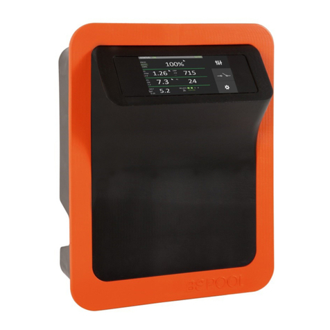
BSV BSPOOL PRO200 User manual

Manual PRO v.2 1 / 53
CLORADOR SALINO
SALT WATER CHLORINATOR
ÉLECTROLYSEUR AU SEL
PRO200 / PRO250 / PRO500 /
PRO750 / PRO1000
MANUAL DE USUARIO
USER MANUAL
MANUEL DE L'UTILISATEUR

Manual PRO v.2 29 / 53
CHLORINATOR INFORMATION
PLEASE NOTE IN THE FOLLOWING CARD THE REGISTRATION DATA OF
THE EQUIPMENT YOU HAVE PURCHASED, WHICH ARE FOUND ON THE SIDE
LABEL.
THESE DATA WILL BE OF USE IF YOU WISH TO MAKE ANY ENQUIRY TO
YOUR SUPPLIER OR TO BSV ELECTRONIC S.L.
MODEL………………………………………………
REF. …………………………………………………..
VOLTAGE……………………………………………..
SERIAL NUMBER.…………………………………………

Manual PRO v.2 30 / 53
INDEX
1-GENERAL DESCRIPTION
1.1- BSV PRO units …………………….. …………….……………………………………………………………………… 31
1.2- Technical specifications……………..…………………………………………………………………………………… 32
1.3- Recommendations and safety precautions…….………………………………………………………………… 32
2- PREPARING THE SWIMMING POOL
2.1- Adding salt to the water ………………………………………………………………………………………………… 33
2.3- Chemical balance of the water..……………………………………………………………………………………… 34
3- INSTALLATION
3.1- General considerations……… ………………………………………………………………………………………… 35
3.2- Hydraulic connection diagram ……..………………………………………………………………………………… 36
3.2.7- Amperometric probe kit ………………… ………………………………………………………………………… 37
3.3- Electrical connection diagram ……..………………………………………………………………………………… 39
4- OPERATION
4.1- PRO units ….. …………………….………………………………………………………………………………………… 43
4.1.1- Main screen………………………………………………………………………………………………………………… 44
4.2- Warning messages and alarms……. ………………………………………………………………………………… 47
5- Maintenance …….………………………………………………………………………………………………………… 49
6- Warranty and service ………………………………………………………………………………………………… 52
Annex 1: Electrical connection schematic ……………………………………………………………………………… 53

Manual PRO v.2 31 / 53
ATTENTION
Before installing the salt water chlorinator, please read this manual carefully. If
you need to clarify any point or have any doubts, please contact your dealer or
BSV ELECTRONIC S.L. directly. We will be delighted to assist you.
1-GENERAL DESCRIPTION
1.2 BSV PRO salt water chlorination equipment
Thank you for purchasing our BSPOOL salt water chlorinator, which will enable
you to enjoy your swimming pool in perfect conditions, without the need to add
any chemical disinfectants.
The salt water chlorination system produces chlorine directly in the filtering
installations by means of electrolysis of slightly salted water. "Free chlorine"
(hypochlorous acid, HClO) is produced which is a strong bactericide. Results are
similar to the chemical products that are normally added.
Saline electrolysis is a reversible process, meaning that once active elements
react with organisms present in the water, it reverts to common salt and water.
The equipment includes an electronic monitoring and regulation control and an
electrolysis cell through which the pool water circulates and which is installed in
the filtering circuit return
If the salt water chlorinator equipment is left to work permanently, it will not be
necessary to change the swimming pool water for several years (8 to 15
depending on its use). You will therefore be collaborating with environment
preservation policies and water management and saving.

Manual PRO v.2 32 / 53
1.2- Technical specifications
1.2.1- Equipment
Models
PRO200
PRO250
PRO500
PRO750
PRO1000
Supply
voltage
230Vac
50/60Hz
230Vac
50/60Hz
230Vac
50/60Hz
230Vac
50/60Hz
230Vac
50/60Hz
Chlorine
production
g/hour
200
250
500
750
1000
Max. power
1350W
1750W
3500W
5250W
7000W
Cell current
36A
45A
45A
45A
45A
Dimensions
Weight
15Kg
20Kg
30Kg
40Kg
50Kg
Protection
IP57
IP57
IP57
IP57
IP57
1.2.2 –Common carachteristics on the PRO units
-Adjustment of chlorine production by switched mode power supply
-Power supply performance >90%
-Automatic switch-off owing to lack of water flow
-Automatic voltage adjustment depending on the concentration of salt and
the temperature, keeping continuous chlorine production.
-Automatic cleaning cycle of electrodes.
-Automatic restart in the event of supply failure.
1.3- Recommendations and safety precautions
-The equipment should always be installed by qualified staff.
-Disconnect the equipment from the mains before performing any
assembly or maintenance operation.
-Make sure that the electrical installation has all compulsory
protection elements (circuit breaker and differential switch) in
perfect condition.

Manual PRO v.2 33 / 53
-It is important to ensure that the supply cables of the
electrolysis cell are tightly connected, otherwise the equipment
could overheat and break down.
-Ensure that the heatsink wings are not blocked and that air can easily
circulate through them.
-BSV PRO equipment incorporate protection systems against short circuits
in the cell, absence of water detector and other safety systems that give
an acoustic and visual alarm in the event of any anomaly. However, for
optimum results, you should ensure the correct hydraulic operation of
your swimming pool.
-Corrosive environments may reduce the lifespan of the equipment. Do
not leave open containers with acids near the equipment.
2- PREPARING THE SWIMMING POOL
2.1- Adding salt to the water
Para que el clorador funcione correctamente deberá incorporarse una pequeña
cantidad de sal y asegurarse de que el nivel de pH del agua sea el adecuado.
Los niveles de sal y pH
recomendados son los siguientes:
pH del agua de la piscina------------------- 7,1 a 7,4
Proporción de SAL en kg/m3-------------- 4 a 6
To ensure that the chlorinator works correctly, a small amount of salt should be
added and the pH level should be suitable.
The recommended salt and pH levels are the following:
pH of the swimming pool water------------------- 7.1 to 7.4
Proportion of SALT in kg/m3-------------- 4 to 6
Although the equipment will start to operate with lower amounts of salt, the
optimum production of salt will be reached with concentrations of over 4kg/m3.
We recommend a concentration of 5Kg/m3 to offset small losses of salt
occurring when cleaning the filter, the effect of rainfall, etc.
To calculate the salt to be added, multiply the total m3 of your swimming pool
x 5.
Example :
A swimming pool measuring 9m in length x 4.5m in width x 1.6m in
depth.
9 x 4.5 x 1.6= 64.8 cubic metres. 64.8 x 5 = 324 Kg of salt to be added.

Manual PRO v.2 34 / 53
We recommend using salt that is especially prepared for use in salt water
chlorination installations,
as it is especially prepared for rapid dissolution and
to achieve optimum results. You can find it at retailers specializing in swimming
pool products.
ATTENTION
When adding salt to the swimming pool, first disconnect the
chlorinator (position OFF), and start-up the filter for 3 or 4 hours, in order for
the salt to dissolve and not to overload the equipment. Once dissolved, start-up
the chlorinator.
It is advisable to add salt to the swimming pool gradually, in 2 or 3 times so as
not to exceed the recommended amount. Excess salt can overload the
chlorinator, in which case it will automatically stop working and water will have
to be added to reduce the concentration.
We also recommend not to add salt near the drain, to avoid undissolved salt
from circulating in the water circuit.
2.2 Chemical balance of the water
The effectiveness of chlorination and the quality of water for healthy bathing,
depends largely on the pH of the water. Therefore, it should be checked
regularly and adjusted as necessary.
There are other parameters which should be considered for the correct
operation of the salt water chlorinator. We recommend an in-depth analysis of
the water when installing a salt water chlorinator.
Parameter
Minimum
Value
Maximum
Value
PH
7.0
7.8
FREE CHLORINE (mg/l)
0.5
2.5
COMBINED CHLORINE (mg/l)
--
0.6
TOTAL BROMIDE (mg/l)
3.0
6.0
BIGUANIDE (mg/l)
25
50
ISOCYANURIC ACID (mg/l)
--
<75
OZONE (GLASS) (mg/l)
--
0
OZONE (before)
0.4
--
TURBIDITY (NTU)
--
<1
OXIDES (mg/l)
--
<3
NITRATES (mg/l)
--
<20
AMMONIA (mg/l)
--
<0.3
IRON (mg/l)
--
<0.3

Manual PRO v.2 35 / 53
COPPER (mg/l)
--
<1.5
ALKALINITY (mg/l)
100
160
CONDUCTIVITY (us/cm)
--
<1700
TDS (mg/l)
--
<1000
HARDNESS (mg/l)
150
250
3-INSTALLATION OF THE EQUIPMENT
3.1- General considerations::
Place the chlorination cell in the highest position possible of the purification
circuit and always after the filter.
If possible, it is recommended to install the cell with a by-pass system with
its corresponding shut-off valves. This is to facilitate maintenance of the cell.
A good earth connection is essential. Use a differential relay with max.
30mA of sensitivity.
If a good quality earth connection is not available, place an
earth connection kit between the electrolysis cell and the redox
probe.OPTIONAL KIT

Manual PRO v.2 36 / 53
3.2- Hydraulic connection diagram
3.2.1- Diagram
Electrolisys cell
Recommended installation (PRO250)
1. FILTRATION
2. CONTROL PANEL
3. FLOW SWITCH
4. ELECTROLYSIS CELL
5. PRO250 UNIT(*)

Manual PRO v.2 37 / 53
Recommended installation (PRO750)
1. FILTRATION
2. CONTROL PANEL
3. FLOW SWITCH
4. ELECTROLYSIS CELL
5. PRO750 UNIT(*)
(*) The PRO250, PRO500, PRO750 and PRO1000 units follows the same
hydraulic scheme, connecting in parallel as many cells as power
modules.
It is highly recommended to install a by-pass system, to be able to block
the water flow in each cell for maintenance purposes.
3.2.2- Amperometric probe kit (free chlorine) OPTIONAL.
Amperometric analysis consists of measuring the intensity of
current generated in the reduction or oxidation reaction of an analyte once
a suitable electric potential is applied.
Current intensity is proportional to the amount of hypochlorous acid
present in the solution.
Bear in mind that hypochlorous acid is a weak acid and as such
its distribution depends on the pH of the medium.
Not only does hypochlorous acid respond to the working potential of the
amperometric sensor, but the hypochlorite also reacts. It is therefore
advisable to compensate the response of the sensor depending on

Manual PRO v.2 38 / 53
the pH value at the middle point, within the range from pH 7.0 to 7.4. Outside
these
ranges of pH, side reactions occur on the surface of the electrode which
prevent the readings generated from being corrected.
3.2.2.1- Indications
STATUS INDICATOR LED
Fixed blue Led: normal operation
Quick flashing blue Led (2Hz): automatic cleaning
Slow flashing blue Led (1Hz): Stabilization time after cleaning.
Fixed red Led: reading outside measurement range
3.2.2.2- Installation
The sensor should be installed where a
constant flow of water is guaranteed, without
the possibility for forming air bubbles in the
measuring cell.
It is recommended to install it in the
Multifunction sensor holder (ref. 44-020), which
is especially designed for this application. It
includes:
1 Flow controller
2 Inlet filter
3 Sampling device
4 pH sensor housing
5 Amperometric probe housing
3.2.2.3- Stabilization of the probe
After downtime or if it is connected for the first time, the sensor
requires conditioning time. Before calibrating the sensor, place it correctly in the
sensor holder, and let water containing free residual chlorine run through for 1
hour, in order to correctly polarize the cell.
If the sensor has been working at 0, without a water flow,
or without water for 1 hour or more, you will have to wait for 60
minutes for the correct polarization of the sensor and to have a correct reading.
The sensor can be passivated if it has been working at over 3 ppm
for hours. In this case, the sensor should be cleaned in an
HC10. 1M solution for 20 seconds. The sensor can then be prepared and
calibrated again.

Manual PRO v.2 39 / 53
3.3- ELECTRICAL CONNECTION DIAGRAM
3.3.1- PRO250/500/750/1000 units
-All the PRO series units can be configured to work with single or three-
phase supply, depending on the installation needs.
-instalación.
Single-phase connection
-Ensure the line supply has all the protections and the correct cable size
according with the current consumption (see table on page 32)
-Remove the upper cover of the unit to be able to see the terminal strips.
-Connect the single-phase cables (230V) to the input strips. The neutral
must be connected to the blue strip while the phase must be connected
to one of the three strips marked as (L1-L2-L3).
-In single-phase configuration, the three phase strips must be connected
together by means of a connection bar (see the following picture
marked with a red circle):
Figura 3.1: Single-phase connection
-Connect the earth cable to the corresponding strip.
-Connect the flow switch to the position shown at 3.3 figure.

Manual PRO v.2 40 / 53
Connection to the three-phase line:
-Ensure the line supply has all the protections and the correct cable size
according with the current consumption (see table on page 32)
-Remove the upper cover of the unit to be able to see the terminal strips.
-Connect the cables to the three-phase line (380V). The three-phase
line has to have neutral and earth connection.
-The connection will be done according with the labels on the strips. The
neutral cable will be connected to the blue strip, while the three phases
must be connected to the L1-L2-L3 inputs.
-Check that the connection bar shown in the 3.2 figure is removed (see
the red circle).
Figure 3.2: Three-phase connection
Synchronization of the unit with the filtration pump:
There are two options to ensure that the chlorination works only when the
filtration pump is on:

Manual PRO v.2 41 / 53
Option A) Line supply by means of the filtration pump contactor:
oConnect the chlorinator’s input line directly to the
filtration pump contactor
oEnsure that the contactor is correctly sized to be able to
hold the pump + chlorinator current (see page 32).
oUse separate contacts to supply the pump and the
chlorinator.
Option B) Chlorinator directly connected to the line, and remote start/stop
activation (recommended):
oConnect the “FILTER“ input of the auxiliary board (see
figure 3.3) to the filtration pump contactor. This contactor
must supply 230V to the “FILTER” input at the same time
that the pump is turned on. The power requirements for
the “FILTER” input is only a few miliampers.
oConnect the input line of the chlorinator directly to the
mains (single-phase or three-phase) depending on how
it’s been configured.
oRemove the LK1 jumper to enable the start/stop mode.
Whith this configuration, the chlorinator will start the chlorine production when
the filtration pump is on, and will stop it when it’s off while a “stop” message is
shown on the display.
Figure 3.3: Auxiliary connection board

Manual PRO v.2 42 / 53
Cell cable connection
All the PRO series chlorinators are supplied with the cables already connected
to its power supplies.
Once the cells are installed, connect every power supply to its cell, using the
included hardware to attach it on every side of the cell.
-Ensure all the cables are tightly connected with the cell.
-In case that the unit has two or more cells, it is advisable to follow the
same rule for all the cell connections (for example: all the brown cables
at the upper side of all the cells, and the blue cables to the down side).

Manual PRO v.2 43 / 53
4- OPERATION
4.1 PRO250, PRO500, PRO750, PRO1000 units
The SMART series equipment has an LCD screen, in which you can view and
configure all operations of the equipment. The following table shows how to
organize the configuration menu of the equipment:
Chlorinator Menu
Chlorinator menu
Main menu
Production %
Free chlorine adjust
Configuration
Superchlorination
Chlorine
Free chlorine probe calibration
Configuration menu
Language
Control
Cell cleaning
When browsing through the menus, an arrow is displayed on the left hand side
which indicates the selected line.
When there is more than one line to select, the buttons enable you to
move the arrow up or down to select the required option. The OK button
confirms selection.
When a value has to be adjusted, for example the time or level of chlorine, the
buttons enable you to increase or decrease the value. Press the OK
button to confirm the value.

Manual PRO v.2 44 / 53
4.1.1- Main screen
On starting up the equipment, a screen will be displayed with the main
parameters.
-En la línea superior se muestra el % de producción de cada una de las
fuentes que incorpore el equipo
-En la segunda línea se muestra la tensión de cada fuente
-La tercera línea muestra la lectura de la sonda de cloro libre, en caso de
estar instalada.
-La cuarta línea muestra el estado del equipo y el modo de control
-The upper line shows the production % of each installed power supply
-The second line shows the voltage of each installed power supply
-The third line shows the free chlorine probe value (it can be hidden on
the control menu)
-The line numbere four shows the unit status and the selected control
mode.
4.1.2- Main menu
Press the "OK" button from the main screen to access the main menu.

Manual PRO v.2 45 / 53
Using the buttons you can select a line of the menu, indicated by the
arrow (). The OK button is used to confirm the selection.
To access the configuration menu, you need to confirm the operation by
selecting (S) through the arrow,and pressing OK.
4.1.3- Language
From the configuration menu select "Language", press the OK button, and once
the required language has been selected, press the OK button and EXIT.
4.1.4- Control
The equipment allows you to select from 2 different modes of control:
Manual: The equipment produces chlorine continuously, depending on the
% of production selected. If you have a fitted FREE CHLORINE PROBE, it will
ignore its value and chlorination will not stop even though the set value has
been exceeded. When selecting this mode, the equipment will ask if you want
to display the value of the PPM on the main screen.
Select this mode if you do not have a FREE CHLORINE PROBE KIT, by
adjusting production and hours of filtering depending on the nature of your
swimming pool, its volume number of bathers and season of the year.
Automatic
Select this mode only if you do not have an Amperometric probe kit. If
you do not have a probe, the equipment will act at random and end up by
stopping and showing an error.
This mode enables you to automatically adjust the level of chlorine in your
swimming pool. Based on the adjusted set value in the "chlorine" menu, the
equipment will stop when it reaches this value, and start-up again automatically
when there is a need for chlorine.
4.1.5- Cleaning
The equipment includes an automatic cleaning system, based on reversing
polarity in the electrolysis cell. These cleaning cycles are performed regularly.
The time between cleaning (in hours) can be adjusted depending on the water
hardness of your swimming pool.

Manual PRO v.2 46 / 53
It is possible to select cleaning intervals from 1 to 8 hours.
4.1.6- Chorine menu
With this menu you can select all parameters related to chlorine production.
4.1.6.1- Chlorine production
Configuration of the maximum production of chlorine.
From 0% to 100% Press “OK” and use the arrows to change the value.
Press "OK" to confirm the adjustment.
Note: Chlorine production may be limited regardless of the operation mode
(manual, automatic...) that is selected.
4.1.6.2- Adjustment of the set value (Max. PPM)
En el cual se instala una sonda de cloro libre (OPCIONAL)
In this case, adjust the value in ppm as required. A value between 1ppm and
1.5ppm is correct.
NOTE: if working in automatic, you can also adjust the production percentage
from 0% to 100%,
On connecting the equipment in automatic mode, the ORP value will
flash for 5 min before the equipment starts to produce chlorine.
4.1.6.3- Free chlorine probe calibration
If you have a free chlorine probe, a menu will appear for you to calibrate it.

Manual PRO v.2 47 / 53
Once the reading has stabilized and the chlorine measurement has been taken
with DPD1,
adjust the PPM value provided by the DPD1 measurement.
4.2- Warning message and alarms
In the event of abnormal operation, the SMART series equipment will display an
alarm message on the 4th line of the screen, together with an acoustic
warning. The alarms shutdown the equipment until the problem is solved.
Similarly, it will display a warning also in the 4th line, but without an acoustic
signal or shutting down the equipment. In this case, the equipment can
continue operating, although you are informed that corrective action should be
taken.
4.2.1- Warning messages
Message:
Causes:
Action required:
"LACK OF SALT"
Lack of salt in the water.
Add salt to the swimming pool.
Incrustations or objects in
the electrolysis cell causing
excess current.
Clean the cell.
The electrolysis cell is worn.
Replace the electrolysis cell with
a new one.
"EXCESS SALT"
Excess salt in the water.
No action required if excess is
not very significant.
Incrustations or objects in
the electrolysis cell causing
excess current.
Clean the cell.
"CLEANING"
The chlorinator is in the
self-cleaning process. The
process lasts 5 minutes
None.
"TEMPERATURE".
The ambient temperature is
>40º
Try and place the equipment in
another position where it is not
over 40º or perform forced
ventilation. Leave the
equipment to rest for a few
minutes.
Consult section number
4. Installation
Other manuals for BSPOOL PRO200
1
This manual suits for next models
4
Table of contents
Other BSV Water Filtration System manuals
Popular Water Filtration System manuals by other brands

Waterway
Waterway Carefree FS016 owner's manual

SpectraPure
SpectraPure CSP Series Installation and operating manual

Everpure
Everpure Coldrink Series Installation and operation guide

Frizzlife
Frizzlife MK99 installation guide

Wynn Environmental
Wynn Environmental 35A Series Assembly instructions

Minolta
Minolta JS-601 installation manual