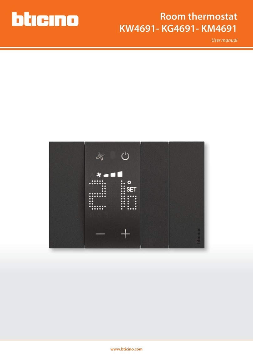
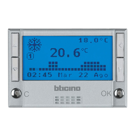
Bticino Legrand MyHome User guide

www.homesystems-legrandgroup.com
Installer manual
Thermostat with display
H/LN4691 - 0 674 59 - 64170

Thermostat with display
Installer manual
3

Contents
3
Thermostat with display
Installer manual
1 Introduction 4
1.1 Warnings and recommendations 4
2 Description 5
2.1 General features 5
2.2 Front view 6
2.3 Rear and side view 7
3 Possible applications 8
3.1 Installation 8
3.2 Function comparison table 10
4 Configuration 11
4.1 Physical or advanced configuration 11
5 Functions and operating modes 12
5.1 Heating and cooling function 12
5.2 Automatic changeover function 13
5.2.1 Automatic changeover in automatic or manual mode (fixed set-point) 14
5.2.2 Automatic switching in Comfort, Eco and Protection mode 15
5.3 Example of installation diagram 17
5.4 Operating modes 20
5.5 Fan-coil speed 20
6 Programming 21
6.1 Display items 21
6.2 Brightness adjustment 24
6.3 Setting the temperature measurement unit 25
6.4 Temperature calibration detected 26
6.5 Modification of the set-point using the keypad 27
7 Appendix 28
7.1 Installation height 28
7.2 Technical data 28
7.3 In case of error 29

54
Thermostat with display
Installer manual
1.1 Warnings and recommendations
Before proceeding with the installation it is important to read this manual very carefully.
The guarantee is automatically void in case of negligence, improper use, tampering by unauthor-
ised personnel.
The thermostat is only suitable for indoor installation.
1 Introduction

54
Thermostat with display
Installer manual
2.1 General features
The thermostat with display can be used in both heating and air-conditioning systems and can
adjust the temperature with five modes: Comfort, Eco, Antifreeze / Thermal protection, Automatic
and Manual.
Depending on the use, the backlit display shows the following information: its function and mode
(heating, cooling or automatic function; Comfort, Eco, Antifreeze/Thermal protection, Automatic,
Temporary manual or Off ), the room temperature measured, the temperature set point set, the
fan-coil fan speed, the local contact status and the zone status.
The thermostat can be used in MyHOME temperature control systems (MyHOME probe with cen-
tral unit), hotel room systems, or residential systems (individual system). The configuration can be
done by connecting the configurators to the corresponding sockets in the back of the thermostat,
or using the MyHOME_Suite software.
Programming is simple and intuitive: to switch from one mode to the other press MODE, +or – .
Factory settings
Heating Cooling
Adjustment interval 3 – 40 °C 3 – 40 °C
Comfort 21 °C 25 °C
Eco 18 °C 28 °C
Antifreeze 7 °C
Thermal protection 35 °C
2 Description

76
Thermostat with display
Installer manual
2.2 Front view
1 - Heating function.
2 - Cooling function.
3 - Manual mode icon.
4 - Comfort mode icon.
5 - Eco mode Icon.
6 - Antifreeze / Thermal protection / OFF mode.
7 - MODE key: a short pressure changes the mode of operation of the device; an extended
pressure (unless used as MyHOME probe) changes the function.
8 - +key: increase the set value.
9 - –key: decrease the set value.
10 - FAN key: set the fan-coil speed on 3 levels + automatic.
11 - Heating On indicator.
12 - Cooling On indicator.
13 - Fan-coil speed indicator, 3 levels.
14 - Fan-coil in automatic mode indicator.
15 - Window indicator: active local contact according to the programming.
16 - Measured (thermometer symbol On) / set (thermometer symbol Off) temperature indicator.
17 - Unit of measure: °C or °F.
2 Description
MODE
+
–
FAN
10
7
8
9
1 2 3 4 5 6
11121314
16
17
15
*( * ) Auto Mode
The remote setting (control unit or
supervision software) follows.
In the case of MyHome systems,
the icons shown with asterisks do
not appear on the display when
the corresponding modes are set
remotely.
NOTE: Some local functions, such
as switching the heating/cooling,
setting the comfort, eco and
antifreeze/heat protection modes
and automatic adjustment of the
fan-coil fan can be disabled when
configuring.
Pressing the pushbutton to activate
one of the deactivated functions will
have no effect.

76
Thermostat with display
Installer manual
2.3 Rear and side view
1 - Configurator socket.
2 - Connection to the BUS.
3 - Local contact.
1
23
ZA / ZB = zone address,
TYPE = Thermostat operating mode (MyHOME probe, hotel thermostat, or
individual residential system);
HEAT = definition of the type of heating load (valves, fan-coil, etc.);
COOL = definition of the type of cooling load (valves, fan-coil, etc.);
PUMP = selection of the pumps to control;
IN = definition of the function performed by the contact connected to the
thermostat.
For the configuration and setup of the local contact see the technical sheet.

98
Thermostat with display
Installer manual
3.1 Installation
Installation in a MyHOME temperature control system
Thanks to the internal sensor, the thermostat can operate as master probe of a MyHOME system. In
this case it will obtain the settings from the central unit managing the system.
Using the +and –keys, it is possible to enter settings different from those of the central unit; the
new settings are temporary, and will only be applied until the next central unit set-point change.
In comfort, eco and antifreeze/heat protection operation the control unit or other control device
cannot change the mode.
To return to the control unit settings, set the mode on automatic (always using the sensor
MODE key).
The systems consists of:
• Power supply;
• Actuators and pumps;
• Temperature control central unit;
• Thermostat with local contact for
the detection of open windows.
Example of MyHOME system
3 Possible applications
PRI
SCS
E49
PRI: 220 – 240 V~
185 – 175 mA
50/60 Hz
SCS: 27 Vdc
600 mA
230 Vac
C1 C2
ART.F430/2
1
1 2 3 4
2 43
OKC
MODE
+
–
FAN
Power supply
Central unit
Thermostat
Actuator
To the
connected loads

98
Thermostat with display
Installer manual
Hotel thermostat
The operation in the hotel room configuration gives the customer the possibility of easily setting
the temperature to the desired level of comfort. The hotel manager can integrate the individual
thermostat installed in the room as part of a system that can be managed using a software for the
monitoring of consumptions, therefore avoiding unwanted energy waste.
Home thermostat
The third type of use, as room thermostat, manages the temperature control of an individual
system, without the need for additional control devices.
The systems consists of:
• Power supply;
• Actuators and pumps;
• Thermostat with local contact for
the detection of open windows.
PRI
SCS
E49
PRI: 220 – 240 V~
185 – 175 mA
50/60 Hz
SCS: 27 Vdc
600 mA
230 Vac
C1 C2
ART.F430/2
1
1 2 3 4
2 43
MODE
+
–
FAN
Power supply
ThermostatActuator
Example of hotel room or individual residential system
To the
connected loads

1110
Thermostat with display
Installer manual
TYPE OF SYSTEM
CAN BE ACTIVATED/
DEACTIVATED BY
MYHOMESUITE
DESCRIPTION MyHOME SYSTEM
MyHome Probe
HOTEL SYSTEM
Hotel thermostat
INDIVIDUAL SYSTEM
Home thermostat MyHOME_Suite FUNCTIONS
Heating or cooling
function setup ·From central unit
·From keypad
(blockable)
·From local contact
·From software
·From keypad (lockable)
·From local contact –
Automatic changeover
function –
Manual Mode ––
Temporary manual
mode – – –
Comfort mode
Eco mode
Antifreeze and Thermal
Protection mode
OFF Mode –
Fan-coil speed ·From keypad
·From remote
·From keypad
·From remote ·From keypad –
3.2 Function comparison table
3 Possible applications
In the table below the first three columns show the functions which can be activated depending
on the type of system in use, while the last column defines which functions can be controlled
locally by the keys on board the sensor. The functions are set in the programming phase using the
MHsuite software.
As an example in hotel systems one can set that the user cannot manage the temperature
adjustment but must call reception so that it is adjusted remotely. Or one can define that all the
local keys are locked to avoid the child in his bedroom using the sensor controls incorrectly.

1110
Thermostat with display
Installer manual
4 Configuration
4.1 Physical or advanced configuration
Depending on personal requirements and the type of system to install, the thermostat may be
configured in two ways: physical or advanced configuration.
The physical configuration is completed by connecting the configurators to the appropriate sock-
ets on the back of the thermostat.
If no physical configurators are connected, the device can be configured virtually by connecting it
to a PC and using the dedicated MyHOME_Suite software.
In this way it is possible to simplify the configuration operations in large systems, without the need
to manually intervene on each device.
The advanced configuration offers more functions, including being able to control several ac-
tuators with just one thermostat and being able to configure the automatic switching mode
(heating/cooling).
For the configuration see the product technical sheet.

1312
Thermostat with display
Installer manual 5 Functions and operating modes
5.1 Heating and cooling function
The thermostat can be set for the management of four different functions, depending on the type
of system to install:
- heating function (only the heating is active);
- cooling function (only the cooling is active);
- cooling function in summer / heating function in winter;
- automatic changeover between cooling and heating (not available in MyHOME systems).
The setting of the function (with the exclusion
of the use as MyHOME probe) can be modi-
fied with an extended pressure of the MODE
( > 7 seconds). The Mode key can disable the
function change (with the configuration by
MyHOME_Suite software).
Heating function
If the measured temperature is lower than the reference value, the heating system is activated and
the corresponding symbol appears on the display .
When the temperature is reached, the thermostat switches the zone off and the icon disappears.
Note: The heating icon is always displayed .
Cooling function
If the measured temperature is higher than the reference value, the cooling system is activated
and the corresponding symbol appears on the display .
When the temperature is reached, the thermostat switches the zone off and the icon disappears.
Note: the cooling icon is always displayed .
Summer / winter function
By configuring the thermostat both for the winter (HEAT) and the summer (COOL) functions, it is
possible to use it with the heating system in winter, and the cooling system in summer.
The icons shown on the display will be the same as the ones previously described for the heating
and cooling functions.

1312
Thermostat with display
Installer manual
5.2 Automatic changeover function
(available starting from version 1.3 of MyHOME_Suite)
(Not available in MyHOME systems).
The thermostat can be programmed for automatic changeover between the heating and the cooling
functions. When programmed in this way, the ( / ) icons are not displayed.
Depending on the temperature measured, the heating or cooling system in operation symbols
(/ ) will appear, to indicate that the corresponding function is active.
Note: Automatic changeover mode cannot be configured physically, but must be enabled during
the advanced configuration (using the MyHOME_Suite software).
This function can be used when it is necessary for the thermostat to automatically manage the
changeover between heating and cooling, and is for example useful in case of 4 tube fan-coils.
Using the MyHOME_Suite software, it is possible to set the range of temperature at different levels,
for the activation of the heating and the cooling systems, depending of the thermal inertia of one’s
own system, and specific requirements.
COOLING
HEATING
CHANGEOVER POINT
CHANGEOVER
POINT
COOLING
HEATING
HEATING
& COOLING
CHANGEOVER
BAND
COMPLETE
CHANGEOVER
DEADBAND
COOLING
HEATING
DEADBAND

1514
Thermostat with display
Installer manual 5 Functions and operating modes
5.2.1 Automatic changeover in automatic or manual mode (fixed set-point)
The switching from the heating to the cooling function, and vice versa, depends on the rules listed
in the following table (T° represents the measured temperature).
NOTE: the automatic changeover threshold has been set to 2°C.
Measured temperature Action
T° between (set-point + automatic changeover
threshold) and (set-point – automatic changeover
threshold).
It maintains the current function.
T° > (set-point + automatic changeover threshold). It switches to the cooling function. 2
T° < (set-point – automatic changeover function). It switches to the heating function. 3
SET-POINT
COOLING
HEATING
TIME
TEMPERATURE
SET-POINT - AUTOMATIC CHANGEOVER THRESHOLD
SET-POINT + AUTOMATIC CHANGEOVER THRESHOLD
Example chart

1514
Thermostat with display
Installer manual
5.2.2 Automatic switching in Comfort, Eco and Protection mode
Automatic changeover depends on the operating mode selected: comfort, eco, or protection.
In this case, the heating and cooling ranges must have been previously set in the corresponding
modes (see paragraph 6.5).
You thus need to set two parameters for each mode: a high set point to be set in the cooling func-
tion and a low set point to be set in the heating function.
Example of temperature range settings
The above example indicates the temperature set-point pairs for Eco mode and Comfort mode.
The cooling system will activate when the temperature exceeds the upper set-point, while the
heating system will activate when the temperature falls below the lower set-point.
COOLING
RANGE
HEATING
RANGE
32°
22°
24°
14°
SET-POINT ECO
SET-POINT ECO 18°
28°
COOLING
HEATING
32°
22°
24°
14°
SET-POINT COMFORT
SET-POINT COMFORT 21°
25°
COOLING
HEATING
COOLING
RANGE
HEATING
RANGE
ECO Mode COMFORT mode
COOLING
RANGE
HEATING
RANGE
32°
22°
24°
14°
SET-POINT ECO
SET-POINT ECO 18°
28°
COOLING
HEATING
32°
22°
24°
14°
SET-POINT COMFORT
SET-POINT COMFORT 21°
25°
COOLING
HEATING
COOLING
RANGE
HEATING
RANGE

1716
Thermostat with display
Installer manual
COOLING
HEATING
TIME
TEMPERATURE
HIGH SET-POINT
LOW SET-POINT
MEASURED TEMPERATURE
The thermostat operates on two different set-points: high set-point, and low set-point.
Example chart
5 Functions and operating modes

1716
Thermostat with display
Installer manual
5.3 Example of installation diagram
4 zone system with 4 tube fan-coil for heating and cooling systems.
Chiller
Boiler
E49
H/LN4691
F430R8
BEDROOM 4
(**)
(*)
PRI
PRI: 220– 240 V~
185– 175 mA
47/63Hz
SCS: 27Vdc
600mA
SCS
E49
MH201
MH201
E49
H/LN4691
F430R8
BEDROOM 1
(**)
(*)
PRI
PRI: 220– 240 V~
185– 175 mA
47/63Hz
SCS: 27Vdc
600mA
SCS
E49
MH201
MH201
E49
H/LN4691
F430R8
BEDROOM 2
(**)
(*)
PRI
PRI: 220– 240 V~
185– 175 mA
47/63Hz
SCS: 27Vdc
600mA
SCS
E49
MH201
MH201
E49
H/LN4691
F430R8
BEDROOM 3
(**)
(*)
PRI
PRI: 220– 240 V~
185– 175 mA
47/63Hz
SCS: 27Vdc
600mA
SCS
E49
MH201
MH201
2 3 45 6
1
DC - In
HUB SWITCH 10/100
LAN network
Computer with supervision software
LAN network

1918
Thermostat with display
Installer manual 5 Functions and operating modes
(*) Connection and configuration detail F430R8
OUT 1 = minimum fan speed
OUT 2 = medium fan speed
OUT 3 = maximum fan speed
OUT 4 = heating solenoid valve
OUT 5 = cooling solenoid valve
F430R8
M
OUT 3
OUT 2
OUT 1
N
L1 L2
F430R8
OUT 5
OUT 4
OUT 3
OUT 2
OUT 1
OUT 5
OUT 4
L
N
230 Vac
BEDROOM 1 ACTUATOR
[ZA] [ZB] [N] [TYPE]
011
BEDROOM 3 ACTUATOR
[ZA] [ZB] [N] [TYPE]
031
BEDROOM 2 ACTUATOR
[ZA] [ZB] [N] [TYPE]
021
BEDROOM 4 ACTUATOR
[ZA] [ZB] [N] [TYPE]
041

1918
Thermostat with display
Installer manual
BEDROOM 1 THERMOSTAT
[ZA] [ZB] [TYPE] [HEAT] [COOL] [PUMP] [IN]
- 1 1 7 CEN - -
(**) Thermostat configuration detail
H/LN4691
BEDROOM 2 THERMOSTAT
[ZA] [ZB] [TYPE] [HEAT] [COOL] [PUMP] [IN]
- 2 1 7 CEN - -
BEDROOM 3 THERMOSTAT
[ZA] [ZB] [TYPE] [HEAT] [COOL] [PUMP] [IN]
- 3 1 7 CEN - -
BEDROOM 4 THERMOSTAT
[ZA] [ZB] [TYPE] [HEAT] [COOL] [PUMP] [IN]
- 4 1 7 CEN - -

2120
Thermostat with display
Installer manual
5.4 Operating modes
The thermostat can operate in the following modes:
Manual / Automatic.
; Temporary manual.
Comfort; 2 customisable set-points: ideal heating and cooling temperatures
(default 21 – 25°C).
Eco; 2 customisable set-points: saving heating and cooling temperatures
(default 18 – 25°C).
Antifreeze: Minimum safety temperature (default 7°C).
Thermal protection: maximum safety temperature (default 35°C).
Off: zone off (can only be set remotely, or by contact).
With a short pressure (3 seconds maximum) of the MODE key, the system toggles between modes.
5 Functions and operating modes
5.5 Fan-coil speed
If the thermostat is configured for the management of a fan-coil type load, by pressing the FAN
key it is possible to scroll through the fan speeds available, selecting one of the following values.
With MyHome suite you can disable the automatic speed setting by local key.
Press FAN to set the fan speed at the desired level.
Note: during the adjustment the fan symbol and
the segment for the speed selected flash.
Speed 1
Speed 2
Speed 3
Automatic operation
Table of contents
Other Bticino Thermostat manuals

Bticino
Bticino Smarther SX8000W User manual

Bticino
Bticino HC 4695 User manual

Bticino
Bticino KW4441 User manual

Bticino
Bticino KW4691 User manual

Bticino
Bticino HC4451 User manual

Bticino
Bticino Smarther SX8000 User manual

Bticino
Bticino L4450 Polyx Clima User manual
Bticino
Bticino MyHOME User manual
Bticino
Bticino LIVING L4448 User manual

Bticino
Bticino XW8002W User manual

Bticino
Bticino L4450 Polyx Clima User manual

Bticino
Bticino Living 4477 User manual

Bticino
Bticino Smarther X8000W User manual

Bticino
Bticino KW4441 User manual

Bticino
Bticino X8000W User manual

Bticino
Bticino HC4451 User manual

Bticino
Bticino HC/HS4451 User manual

Bticino
Bticino KW4691 User manual
Bticino
Bticino Smarther User manual