manuals.online logo
Brands
  1. Home
  2. •
  3. Brands
  4. •
  5. Bubble
  6. •
  7. Stove
  8. •
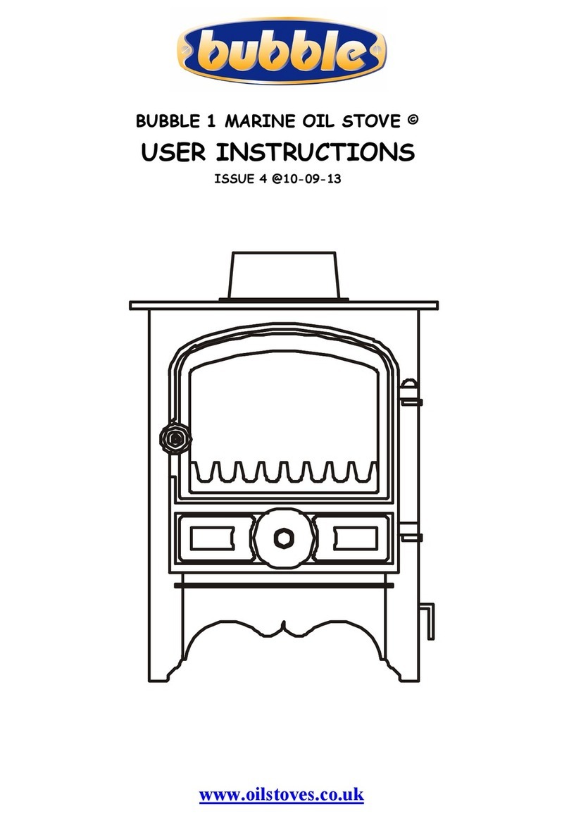
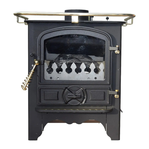
  9. Bubble BOAT B1 Quick start guide

Bubble BOAT B1 Quick start guide

Draught copy needs finishing
www.oilstoves.co.uk
ALL MARINE OIL STOVES ©
COMMON INSTALLATION INSTRUCTIONS
ISSUE 6 @ 11-01-13
2
INDEX
1. BEFORE STARTING THE JOB................................................................ 3
FITTING OPTIONS....................................................................................................................................................................... 3
ABOUT THE STOVES.................................................................................................................................................................... 3
2. SAFETY. ........................................................................................ 4
FUMES............................................................................................................................................................................................... 4
FIRE ................................................................................................................................................................................................... 4
BURNS............................................................................................................................................................................................... 4
CLEARANCES FROM COMBUSTIBLES..................................................................................................................................... 5
CLEARANCES FROM COMBUSTIBLES-FLUE PIPES ............................................................................................................ 5
VENTILATION. .............................................................................................................................................................................. 5
FLOODED VAPOURIZING BURNER POTS. ............................................................................................................................. 5
SECURELY FIX THE APPLIANCE............................................................................................................................................... 5
3. CHIMNEY....................................................................................... 5
THE HEIGHT. .................................................................................................................................................................................. 5
THE DIAMETER.............................................................................................................................................................................. 5
THE TEMPERATURE OF THE GASSES IN IT........................................................................................................................ 5
THE RESISTANCE OF THE INNER SURFACE OF THE FLUE PIPE OR PIPES.............................................................. 5
THE TYPE OF TERMINAL. ........................................................................................................................................................... 5
THE PREVAILING ATMOSPHERIC CONDITIONS............................................................................................................... 5
THE CHIMNEY RULES.................................................................................................................................................................. 6
4. FUEL SUPPLY................................................................................... 6
WAXING........................................................................................................................................................................................... 6
AIR LOCKS ....................................................................................................................................................................................... 6
TRIM.................................................................................................................................................................................................. 6
TANK.................................................................................................................................................................................................. 6
OIL LINE .......................................................................................................................................................................................... 6
WATER CONTAMINATION........................................................................................................................................................ 7
REMOTE SENSING FIREVALVE ................................................................................................................................................ 7
ISOLATION VALVES.................................................................................................................................................................... 7
SLEEVING. ....................................................................................................................................................................................... 7
OVERBOIL OR OVERHEAT PROTECTION OF THE APPLIANCE....................................................................................... 7
5. FIREPLACE. .................................................................................... 7
DISTANCES FROM COMBUSTIBLES (STOVES) .................................................................................................................. 8
DISTANCES FROM NON COMBUSTIBLES (STOVES)........................................................................................................ 8
DISTANCES FROM COMBUSTIBLES (FLUE PIPES)............................................................................................................ 9
FIG 1. STOVE DISTANCE FROM COMBUSTIBLES .............................................................................................................. 9
FIG 2 HARWORTH FABRICATED DECK FLANGE LAYOUT.............................................................................................. 10
FIG 3 TYPICAL OIL FEED LAYOUT ........................................................................................................................................ 10
FIG 4 TYPICAL PLUMBING CIRCUIT LAYOUTS.................................................................................................................. 11
6. NORMATIVE REFERENCES ..................................................................12
If you have any difficulties please phone our technical help line on-:
01302 742520 fax 01302 750573
e mail [email protected].
www.oilstoves.co.uk
3
1
1.
.B
BE
EF
FO
OR
RE
ES
ST
TA
AR
RT
TI
IN
NG
GT
TH
HE
EJ
JO
OB
B.
.
THE FOLLOWING NOTES PROVIDE INFORMATION
FOR INSTALLATION OF THE FOLLOWING
APPLIANCES.
Boat Bubble No 1, Dry Small and Large Boiler Stoves
Boat Bubble No 2 Dry Small and Large Boiler Stoves
Marine Corner Bubble Wet and Dry stoves
Marine Round Bubble Wet and Dry stoves
Marine Belfort Wet and Dry stoves
FITTING OPTIONS.
There are normally three different situations that the
installer may be faced with-:
A new build installation.
An established boat installation, (which has not had a
oil stove fitted).
A replacement installation, where there has been a
solid fuel stove fitted previously.
Each of the situations will present differing problems
which will be-:
Where to locate the stove.
How to deal with fireplace design.
Where to locate the oil tank.
How to get an oil supply to the stove.
How to fit the chimney.
How to connect water to the stove.
How to disconnect and remove the stove,
easily.
The new build situation should be the easiest.
The established boat situation will require careful
attention to the sighting of the stove in relation to
flue positions and existing fittings positions.
In replacement situations it may well be necessary to
blank off the existing through roof flue position and
cut a fresh one to suit the new location.
ABOUT THE STOVES
The stove is a space heater, which burns diesel oil in a
controlled manner utilizing a chimney to discharge the
products of combustion.
The stove generates heat from burning oil mixed with
air in a vaporizing pot located in the bottom of the
stove.
Once ignited, oil goes into the pot at a steady and
controlled rate via gravity flow, metered by the OIL
CONTROL VALVE the oil flow can be controlled from
minimum to maximum or any setting in between
determined by where you set the oil flow control knob.
Air is sucked into the pot by the natural action of the
negative pressure in the chimney and to allow the
chimney to work correctly it is essential that you have
adequate, unrestricted ventilation into the area where
the stove is situated.
The amount of oil that can be successfully burned is
directly proportional to the amount of air that the
chimney can draw into the pot and so to achieve
adequate combustion a balanced and appropriate flow
of both oil and air is required.
The stove will provide space or combined space and
water heating.
There are three versions of the stove
Space heating only.
Space heating and a small boiler
Space heating and a large boiler.
On the boiler versions there are 2 x 1" BSP female
sockets for water connections to be made.
Both boilers are high water content and suitable for
pumped or gravity systems, pressurised or open
vented, provided that they are correctly designed.
The stove incorporates a removable front apron, which
on manual ignition stoves is used to gain access for
lighting.
On the right hand side of the stove is a small lever
which should be rotated occasionally to descale the oil
inlet pipe.
The stove must not be operated with the glass front
door opened or cracked, or without the lighting port
plug fitted.
The door glass may require light cleaning occasionally
depending upon the continuous running time of the
stove.
The stoves must be securely bolted down so that it
can resist impact or collision and it must be level in
both directions.
4
The top of the stoves can be used for warming and
cooking.
Some stoves can also be supplied with or without a coal
kit.
Just like a solid fuel stove, coal effect will only be
available when the stove is running at maximum or near
maximum performance which is 4kW OR 14,000 B.T.U,
s PER HOUR.
Suitable deck flanges and flue systems must be used.
We strongly advise the use of a suitable anti
downdraft terminal.
CONTROLS
The output of the stove is regulated by the amount of
oil allowed to go into it and this function is controlled
by the -:
OIL CONTROL VALVE (O.C.V.),
Turning the knob anti clockwise controls the oil flow.
Controls for the stove will vary, depending on which
valve is fitted to it.
The valve could be a ships valve or a Toby valve.
The control for the dry stove comprises-:
1. Oil flow control only. (Ships Valve)
The boiler version has extra controls which are-:
1. Oil flow control
2. Oil valve trip lever
3. Thermostat control
4. Overheat device with manual re-set.
The Toby oil control valve used on boiler stoves has a
modulating thermostat control, which will put the fire
on to low fire when the target temperature has been
achieved.
In addition to this there is also a device which will
shut the burner down, should the water exceed 90 deg
C., the device can be reset should it trip off.
The Toby valve has to be tripped into action by lifting
the trip button.
The flow of oil into the pot can be adjusted via the
knob on top of extension rod rising up from the oil
control valve.
2
2.
.S
SA
AF
FE
ET
TY
Y.
.
Take care to make sure that safety and ventilation
issues are adequately addressed.
FUMES
Always fit a suitable Smoke and Carbon Monoxide
alarm.
Make sure that the function is checked on regular
basis.
Fit the alarms in such a position that in the event of
an alarm being triggered the noise from it will wake
you up should you be sleeping.
Here are the main causes of fume or smoke to leak
from the stove.
The chimney is blocked.
There are too many bends in the chimney.
The above deck chimney extension is not high
enough.
The boat is moored in a position near to high
buildings or trees and downdraughting is
occurring.
The chimney is not airtight.
There are unusually strong cross winds
If downdraughting occurs turn the appliance off until
the winds subside.
FIRE
Fire can be caused by a variety of potential danger
points and because of the space limitation on boats;
this risk is ever present and must be adequately
assessed.
The main danger is the effects of heat from the stove
on combustible materials and boat occupants.
Make sure that all combustibles are adequately
protected from the effects of heat radiation.
The stove must stand on a fireproof base of minimum
thickness 30mm.
Floors in front of the stove must have suitable fire
protection.
Built in stove heat shields should not be removed
under any circumstances.
BURNS
During normal, day-to-day use, many parts of the
stove, pipe work, and chimney will become too hot to
touch.
These hot surfaces must be adequately protected to
prevent anyone falling on to, or touching them.
5
Suitable fireguards for the appliance and chimney
must be fitted.
Fireguards must comply with BS6539.
Always use heatproof gloves when working on or near
to a hot stove.
CLEARANCES FROM COMBUSTIBLES
The stoves must be fitted in line with the distances
specified in the table.
All hearths and fireplaces must be made from non-
combustible materials.
CLEARANCES FROM COMBUSTIBLES-FLUE PIPES
Flue pipes must be fitted in line with the distances
specified in the table.
Any combustible materials within the specified
distances from the stoves must be protected by a
suitable heat shield.
Protection can be gained by the use of -:
Sheet metal heat shields and spacers.
Heat resistant boards such as TAC board.
Combustible materials can be-:
Wooden furniture.
Curtains.
Wooden panels or frames adjacent to the flue
pipe or where it passes through the deck of
the boat.
Carpet or flooring close to the stove.
Items near to the stove, which could fall onto
it and ignite, should the boat suffer a slight
impact or collision.
VENTILATION.
Ventilation plays a vital role in the fitting and sighting
of any stove.
The provision of ventilation for these stoves is
adequately covered by the requirements of the boat
safety scheme.
25cm2 minimum permanent ventilation, directly to
outside air, must be provided.
FLOODED VAPOURIZING BURNER POTS.
When attempting to light a stove, make sure that the
pot is not flooded with oil by looking into the base of
the burner.
If it is flooded remove the excess oil as per
instructions in the faultfinding manual.
Never try to relight a hot stove; wait until it has
cooled down.
Hot oil vapour is explosive.
Never try to light a flooded pot.
SECURELY FIX THE APPLIANCE
The stove must be securely fastened down so that it
can resist impact or collision and it must be level in
both directions.
Level the stove in both directions when the vessel is
midway between its maximum and minimum trim
conditions.
Bubble stoves must not be fitted if the maximum
angle of trim exceeds 1 deg forward to aft or port
to starbord.
The stove must not be operated with the glass front
door opened or cracked, or without the lighting port
plug fitted.
Qualified persons can only install unvented plumbing
systems.
A suitable and serviceable fire extinguisher should
always be readily accessible.
3
3.
.C
CH
HI
IM
MN
NE
EY
Y
This is the one of the most interesting problems the
installer has to deal with and as the chimney affects
most aspects of running the stove, we take time here
to list the following information for your
consideration.
The power, (
suck or vacuum the chimney can develop
)
depends upon the following-:
THE HEIGHT.
THE DIAMETER.
THE TEMPERATURE OF THE GASSES IN IT.
THE RESISTANCE OF THE INNER SURFACE OF
THE FLUE PIPE OR PIPES.
THE TYPE OF TERMINAL.
THE PREVAILING ATMOSPHERIC CONDITIONS.
It is obvious that on a boat all the above elements are
in short supply.
6
Normally, we have low flues which are small in
diameter and generally not very well insulated, coupled
with all these problems we have an other one, which is
that the boat moves across constantly changing
surroundings, through locks, into headwinds and
crosswinds, all creating major opportunity for down
draughting to occur.
Any bend in any part of the chimney or roughness on
the internal chimney wall will slow down the velocity of
rising gases and reduce the effectiveness of the
chimney.
Any slight reduction in the flue gas temperature will
reduce the chimney vacuum or pull, hence when the
stove is slowed down for all night burning, as the flue
gas cools down the chimney vacuum reduces and as the
chimney vacuum drops, the stove may well start to
burn sooty. This problem is highlighted even more
during very cold weather when the chimney can cool
down even faster. In these situations careful
attention to servicing and low fire setting is essential.
THE CHIMNEY RULES.
1. Always use a top outlet for flue pipe take off.
2. Always try to get the stove as low as possible
in the boat, this will allow installation of
maximum length flue pipe.
3. Clean or have the chimney cleaned regularly.
(Frequency depends upon type of fuel and
length of time used).
4
4.
.F
FU
UE
EL
LS
SU
UP
PP
PL
LY
Y.
.
There are several problems relating to diesel fuel
supply, which need be adequately addressed.
WAXING
Cold weather waxing or thickening alters the flow
characteristics of diesel.
An adequate fuel feed supply can turn into an
inadequate one when the temperature starts to fall.
The worst scenario is fuel feed pipe 50-60 feet long in
8mm dia pipe.
The best-case scenario is a fuel pipe 4 feet long in
10mm dia with insulated lagging.
AIR LOCKS
Air lock in oil feed pipework must be avoided.
The pipe work must slope down to the appliance and be
clipped level at 500mm intervals to prevent sagging.
Any rises in the pipework will cause air locks on
commissioning and after future oil run out situations,
if it is not possible to run the pipework in a steady
slope then where changes occur a vertical venting leg
should be fitted.
TRIM
Bubble stoves must not be fitted if the maximum
angle of trim exceeds 0.75 deg forward to aft or
port to starbord.
Level the stove in both directions when the vessel is
midway between its maximum and minimum trim
conditions.
A minimum pressure head of 10" is required.
This head is measured from the base of the oil tank to
the top of the oil control valve. In some cases this
head can be affected by the ballast or trim of the
boat.
Take great care to try out all the different ballast
and trim possibilities to make sure that adequate oil
feed is always available at the outlet end of the fuel
pipe before it enters the oil control valve at the stove.
TANK
If the stove is fitted at the bow of the boat, a bow
tank is recommended.
The tank should comply with the requirements of the
boat safety scheme and have-:
A conveniently sized filler
A means of venting.
A conveniently located, easily visible, contents
gauge.
An isolation valve
An easily replaceable cartridge filter.
A suitable and substantial water trap
Do not use glass filter bowls, they are not acceptable
under the boat safety scheme.
Make sure that you fuel supplier supplies you with
appropriate fuel for wintertime running.
OIL LINE
The oil feed line starts after the fuel filter and
proceeds to the point of entry, which is where the oil
line goes into the cab or saloon of the boat.
7
The diameter of the oil line is dependant upon the
length of run. See 3-2 on waxing and make sure that
you have suitably sized compression fittings available.
At this point it is necessary to fit a 60 DEG C, remote
sensing fire valve, designed to shut off the oil supply,
should a fire occur near to the stove.
If the bubble stove is fitted up to the first bulkhead
it will be necessary to fit the isolation valve outside
the cabin or saloon of the boat.
WATER CONTAMINATION
Because of the high risk of fuel contamination with
water, we strongly recommend the fitting of a high
volume water trap, in the oil supply line.
REMOTE SENSING FIREVALVE
The fire valve has a capillary tube on the end of which
is a temperature sensitive phial, run the capillary tube
with the oil line up to the stove and carefully fit the
sensing phial 15mm pipe clips in front of the drip tray
on the fireplace hearth, directly in front of the
combustion air restrictor.
Before it is fitted try the fender on the stove to
make sure that the fender does not fowl the sensing
phial.
The sensing phial may be visible through the bottom of
the fender, to mask it, paint it with matt black paint
available from our sales desk.
When fitting the fire valve make sure that where the
capillary and oil line go through the bulkhead in
separate sleeved tubes, so that the capillary can be
withdrawn separately should it ever need replacing.
For fitting of long oil feed lines which pass through
bulkheads and various other parts of the boat it may
well be necessary to fit more than one fire valve,
especially where the oil line passes through an area
where a fire could occur i.e. kitchen area etc.
ISOLATION VALVES.
Two isolation valves are required, one fitted directly
into or close to the oil control valve to allow you or the
service man to turn the oil off should the need arise,
and one fitted directly into the oil tank before the
fuel filter.
Always turn off the oil isolation valve serving the
appliance before leaving the vessel unattended.
SLEEVING.
Where the oil line goes through the boat
superstructure a suitable bulkhead fitting must be
used.
OVERBOIL OR OVERHEAT PROTECTION OF THE
APPLIANCE.
Where Toby aquastats have not been fitted to the oil
control valve, an additional 90 DEG C, remote sensing
fire valve fitted either into, or close to the oil control
valve may be fitted.
The sensor from this valve has to be attached to the
water jacket or the hot outlet pipe from the boiler.
The valve is calibrated to shut the oil supply down
should the water temperature exceed 90 Deg C.
There is a re set button which needs to be pressed in
to re set the valve after it has tripped off.
5
5.
.F
FI
IR
RE
EP
PL
LA
AC
CE
E.
.
Always fit the stove on a suitable drip tray.
The possibility of oil drops leaking from the stove
must be considered, a suitable oil drip tray must be
fitted and designed in such a way, as it will contain any
oil leaks or drips.
Normally the tray will cover the footprint of the
stove, the oil valve and isolation device.
It will be oil tight and have a vertical upstand of at
least 30mm. This should give a minimum containment
volume of 2 litres.
It will be securely fastened down to the vessel and
the appliance must be securely fastened down to the
oil drip tray.
Make sure that drip trays are tested to ensure that
they do not leak when filled with oil.
Use materials, which are easy to keep clean and
fireproof such as tiles, asbestolux or vermiculite
boarding.
The hearth must be-:
FLAT - SECURE - FIREPROOF AND LEVEL IN BOTH
DIRECTIONS.
The vertical walls of the fireplace must be made from
fireproof materials.
Use fireproof, rockwool infill behind the fireplace
panels to protect any combustible insulation materials
such as spray foam.
8
DISTANCES FROM COMBUSTIBLES (STOVES)
Stove
Type
ABOVE
SIDES.
BACK
FRONT
HEARTH Non Combustible
Material
BOAT B1
500
300
150 FROM
HEAT SHIELD
300 to allow
door opening.
30MM THICK x 100 projection
at the front and sides
BOAT B2
600
300
150 FROM
HEAT SHIELD
300 to allow
door opening.
30MM THICK x 100 projection
at the front and sides
BELFORT
500
300
150 FROM
HEAT SHIELD
300 to allow
door opening.
30MM THICK x 100 projection
at the front and sides
CORNER
500
75
75 FROM
HEAT SHIELD
300 to allow
door opening.
30MM THICK x 100 projection
at the front.
ROUND
200
ALLOW 300 ALL ARROUND THE STOVE
30MM THICK x 100 projection all
round
DISTANCES FROM NON COMBUSTIBLES (STOVES)
Stove
Type
ABOVE
SIDES.
BACK
FRONT
HEARTH Non Combustible
Material
BOAT B1
300
150
150 FROM
HEAT SHIELD
300 to allow
door opening.
30MM THICK x 100 projection
at the front and sides.
BOAT B2
300
150
150 FROM
HEAT SHIELD
300 to allow
door opening.
30MM THICK x 100 projection
at the front and sides.
BELFORT
300
150
150 FROM
HEAT SHIELD
300 to allow
door opening.
30MM THICK x 100 projection
at the front and sides.
CORNER
200
150
25 FROM
HEAT SHIELD
300 to allow
door opening.
30MM THICK x 100 projection
at the front and sides.
ROUND
200
ALLOW 150 ALL ARROUND THE STOVE
30MM THICK x 100 projection
9
DISTANCES FROM COMBUSTIBLES (FLUE PIPES)
For all stoves-:
1. Horizontal Distance = 50 for single skin pipes when fitted in the deck flange at the top of the chimney
system, protected by the fire stop spacer.
2. Horizontal Distance = 150 when exposed in the saloon or living space.
3. Horizontal Distance = 30 mm for insulated flue pipe systems.
FIG 1. STOVE DISTANCE FROM COMBUSTIBLES
10
FIG 2 BUBBLE FABRICATED DECK FLANGE LAYOUT
FLEXIBLE FIRE CEMENT
GLASS FIBRE ROPE
FIRESTOP SPACER
TRIM TIMBER
DECK FLANGE
FASTENERS
CEILING RING
CEILING RING
FIRESTOP SPACER
PLAN VIEW OF ARRANGEMENT
FIG 3 TYPICAL OIL FEED LAYOUT
11
FIG 4 TYPICAL PUMBING LAYOUTS
Drg 1
HT
11
COPYRIGHT
BUBBLE PRODUCTS 2013
PCF
10
AAV
DRAIN DOWN
35MM COPPER PIPEWORK
CALORIFYER SIZED TO SUIT
FLOW
DRAIN COCK
AAV
AAV
EXPANSION VESSEL
potable water
EXPANSION VESSEL
KIT 77-07-020
R1 R2 TOWEL RAIL
SV
77-07-017 77-07-017
77-07-021
77-07-017
S C H E M A T I C G R A V I T Y S Y S T E M
Drg 2
HWP
6
HT
11
COPYRIGHT
BUBBLEPRODUCTS2013
PCF
10
DRAINCOCK
CALORIFYERSIZEDTOSUIT
22mmHEP2O
28mmCOPPER
FROMSTOVE
AAV AAV
DRAINDOWN
KIT77-07-020
R1 R2 TOWELRAIL
SV
77-01-09124V
77-01-09012V
77-07-017 77-07-017
77-07-021
EXPANSIONVESSEL
EXPANSIONVESSEL
potablewater
SCHEMATICPUMPEDSYSTEMISS1OF08-07-01
Drg 3
77-07-017
AAV
COPYRIGHT
BUBBLE PRODUCTS 2013
77-07-017
AAV potable water
EXPANSION VESSEL
BATH
BED
HALL
TOWEL RAI L
NOTE
BOILER MUST HAVE A SAFETY VALVE FITTED
SCHEMATIC 2 PUMP SYSTEM
USING LARGE BOILER BUBBLE OIL STOVE
PT NO BB1-3.5-1.5B
boi ler return
boi ler flow
COMMON RETURN
TD
14
NRV
7
RAD 2RAD 1
EV
2
CALORIFYER SI ZED TO SUI T
CS
HT
PCF
12
10
15
NRV
CHP
HWP
7
8
6
14
12
11
10
8
7
6
5
3
2
15
with safety valve and tundish
PRESSURISED COLD FEED
CYLINDER STAT
NON RETURN VALVE
HOT WATER PUMP
CENTRAL HEATI NG PUMP
AUTO AIR VENT
HOT TAPS
SAFETY VALVE
TUNDISH
PRESSURE GAUGE
SV
2
1
3
HT
11
1EXPANSION VESSEL AND FILLING LOOP
EXPANSION VESSEL potable water
12
© HARWORTH HEATING LTD 30.6.98
This publication may not be copied by any means, without written permission
from the authors.
These products are subject to continuous development and improvement and it
is consequently acknowledged that due to this process there may be some
omissions and errors.
This publication is intended only to assist the reader in the use of this product
and therefore Harworth Heating Ltd shall not be liable for any loss or damage
whatsoever arising from the use of any information, error or omission found in
this publication.
The appliances mentioned in this publication can
only be installed and serviced by approved
personnel.
Approved personnel means that they must HAVE
BEEN SUITABLY TRAINED.
For details of suitable training courses contact :-
www.oftec.org
6
6.
.N
NO
OR
RM
MA
AT
TI
IV
VE
ER
RE
EF
FE
ER
RE
EN
NC
CE
ES
S
Boat installation work comes under the control of:-
The Boat Safety Scheme.
This scheme provides statutory requirements and
associated EN / BS Standards for most aspects of
installation work on boats.
Further information and a copy of the requirements
can be obtained from:-
www.boatsafetyscheme.com
Where guidance for oil fired appliances is not readily
available from the Boat safety Scheme publication, we
then point out a list of standards which pertain to
domestic installations and which are generally covered
by the latest version of the English Building
Regulations Doc J.
When read in conjunction with :-
1. Our installation instructions.
2. The Boat Safety Scheme rules.
3. The other standards detailed, enough information
should be provided to allow for a safe installation.
BS 5440 Flues.
BS
6999 Flues
BS 7840 Fuel Hoses.
BS EN1057 Copper Tubes.
BS1344 Part 3 1988 ISO8290 1987 Flues.
BS
EN 1443:2003
C
h
i
mn
e
y
s –
Generalr
e
qu
ir
e
m
e
n
t
s.
BS EN1856 part 1 replacing BS 4543 Flues.
BS EN1856 part 2 & BS 715 1993 Flues.
BS 1945: 1971 Stove door
BS
EN 10296-1 S
teeltubes
BS ISO 10088:2001
BS EN ISO 9094-2003
BS
EN 10297-1 S
teel
t
ub
e
s
BS
EN 13384-1
C
h
i
mn
e
y
s
BS
EN 10088-1:2005 S
t
a
i
n
l
e
ss
s
t
ee
ls –
P
a
r
t
1:
L
is
t
ofs
t
a
i
n
l
e
ss s
t
ee
ls
http://www.oilstoves.co.uk/webdocs/articles/Boat_Flu
e_Systems.pdf
http://www.oilstoves.co.uk/webdocs/technical/Bubble
/Bubble_Corner_Oil_Installation_Instructions.pdf

Other manuals for BOAT B1

1

This manual suits for next models

5

Other Bubble Stove manuals

Bubble 2 Rayburn Regent User manual

Bubble

Bubble 2 Rayburn Regent User manual

Bubble CORNER SOLID FUEL STOVE User manual

Bubble

Bubble CORNER SOLID FUEL STOVE User manual

Bubble Boat Bubble No 1 Instruction manual

Bubble

Bubble Boat Bubble No 1 Instruction manual

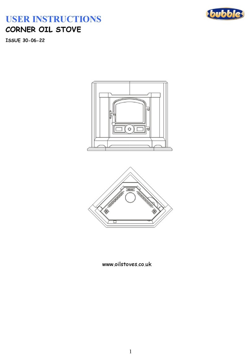
Bubble CORNER OIL STOVE User manual

Bubble

Bubble CORNER OIL STOVE User manual

Bubble 1 MARINE OIL STOVE User manual

Bubble

Bubble 1 MARINE OIL STOVE User manual

Bubble 2 Rayburn Regent Service manual

Bubble

Bubble 2 Rayburn Regent Service manual

Bubble Round Marine User manual

Bubble

Bubble Round Marine User manual

Bubble Bb1 Operating instructions

Bubble

Bubble Bb1 Operating instructions

Bubble BELFORT MARINE User manual

Bubble

Bubble BELFORT MARINE User manual

Bubble 4b half pod Operation manual

Bubble

Bubble 4b half pod Operation manual

Bubble B1 HALF POD MARINE OIL STOVE User manual

Bubble

Bubble B1 HALF POD MARINE OIL STOVE User manual

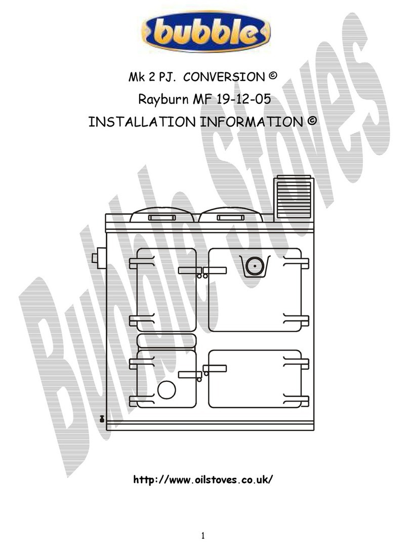
Bubble Mk 2 PJ. CONVERSION Rayburn MF 19-12-05 Service manual

Bubble

Bubble Mk 2 PJ. CONVERSION Rayburn MF 19-12-05 Service manual

Bubble 1 MARINE OIL STOVE User manual

Bubble

Bubble 1 MARINE OIL STOVE User manual

Bubble CORNER User manual

Bubble

Bubble CORNER User manual

Bubble Bb2 User manual

Bubble

Bubble Bb2 User manual

Popular Stove manuals by other brands

Alfa Plam CFA XILA Instructions for installation, use and maintenance manual

Alfa Plam

Alfa Plam CFA XILA Instructions for installation, use and maintenance manual

Morso DB15 Installation and operating instructions

Morso

Morso DB15 Installation and operating instructions

Morso 3600 Series Installation and operating instructions

Morso

Morso 3600 Series Installation and operating instructions

RIKA INTERNO Assembly instructions

RIKA

RIKA INTERNO Assembly instructions

MCZ CLUB AIR 10 M1 OPERATION AND CLEANING

MCZ

MCZ CLUB AIR 10 M1 OPERATION AND CLEANING

Diamond G2 Series operating instructions

Diamond

Diamond G2 Series operating instructions

Rocal TERMOGAR W1501 user guide

Rocal

Rocal TERMOGAR W1501 user guide

PENTAGAST cookmax CXE4F65/650 operating instructions

PENTAGAST

PENTAGAST cookmax CXE4F65/650 operating instructions

StoveMaestro 016B Installation and operation manual

StoveMaestro

StoveMaestro 016B Installation and operation manual

Flavel Arundel FCMSB Installation and operating instructions

Flavel

Flavel Arundel FCMSB Installation and operating instructions

WARRIOR Stoves WSDGAB manual

WARRIOR Stoves

WARRIOR Stoves WSDGAB manual

Expondo UNIPRODO user manual

Expondo

Expondo UNIPRODO user manual

Morso 8140 Installation and operating instructions

Morso

Morso 8140 Installation and operating instructions

Stanley Erin Installation and operating instructions

Stanley

Stanley Erin Installation and operating instructions

Jøtul GF 400 DV Sebago Installation and operation instructions

Jøtul

Jøtul GF 400 DV Sebago Installation and operation instructions

England's Stove Works 25-PDVC Installation & operation manual

England's Stove Works

England's Stove Works 25-PDVC Installation & operation manual

Piazzetta P158 T Product Information, Installation and Maintenance

Piazzetta

Piazzetta P158 T Product Information, Installation and Maintenance

Harman Stove Company PC 45 Installation and operating manual

Harman Stove Company

Harman Stove Company PC 45 Installation and operating manual

manuals.online logo
manuals.online logoBrands
  • About & Mission
  • Contact us
  • Privacy Policy
  • Terms and Conditions

Copyright 2025 Manuals.Online. All Rights Reserved.