manuals.online logo
Brands
  1. Home
  2. •
  3. Brands
  4. •
  5. Bucktool
  6. •
  7. Power Tools
  8. •
  9. Bucktool DP12VL User manual

Bucktool DP12VL User manual

12"Variable Speed Drill Press
With Laser & Worklight
INSTRUCTION
MANUAL
IMPORTANT:
For your own safety, read and follow all of the Safety
Guidelines and Operating Instructions before operating
this product.
GET IT DONE !
Contact Us:
email: service@bucktool.com
https://www.bucktool.com
909-255-1088 (8AM-5PM PST)
Brand Concept
Brand Story
Redefining Efficiency -- BUCKTOOL.
Buck It,Redefining Efficiency -- BUCKTOOL
Customer Priority ,High Quality Standard,Impeccable After Sale Service
This is a concept that is at the core of everything we do as a brand and it is what
allowed us to become the brand we are today.
The Customer Priority ,High Quality Standard,Impeccable After Sale Service is a
commitment that starts at the design of our products and ends with our customers
receiving their end product. We possess the capbility to produce expertise but
affordable products, combine this with personalized design and deliver this all with
exclusive products to our customers. This trio is what separates us from other
brand who only provide what we provide at a fraction of the expertise. We are
able to deliver our Customer Priority ,High Quality Standard,Impeccable After Sale
Service through out the entire delivery process of our product lines and this concept
is what drives us every day at BUCKTOOL to be the brand we are.
We’re BUCKTOOL. We’ve been dealing with the manufacturing of power tools for
many years. Our concept focus on Customer Priority ,High Quality Standard,
Impeccable After Sale Service which has allowed us to deliver products with high
quality, excellent customer service and reasonable price to our customers. This
lethal trio is embedded in to the core of our brand and is what allows to be the
unique power tools manufacturer and supplier worldwide. Our business, experience,
and technology is built on a foundation of power tools expertise we’ve built for
decades. Through a combination of years of hard work and experience we’ve been
able to bring you the BUCKTOOL brand you see today. We live for challenges and
strive to make our customers 100% satisfied. What BUCKTOOL does for customers
is special, and we want to share this with you.
2
Specifications
Safety guidelines
Package contents
Key parts diagram
Operating instructions
Maintenance
Troubleshooting
Exploded view
Parts list
Warranty
TABLE OF CONTENTS
SPECIFICATIONS
TABLE OF CONTENTS
DP12VL
2
3
10
11
12
23
24
25
29
30
Specifications
Input 120VAC, 60Hz
Chuck
Table size
Table Movement
Overall Height
9-17/32" x 9-17/32"
45° bevel
Speed
Swing
Spindle Travel
580~3200RPM
Motor
1/32" - 5/8"
6.2A
12"
2"
39"
3
SAFETY GUIDELINES
DP12VL
GENERAL SAFETY RULES
Read and understand all instructions. Failure to follow all instructions listed below,
may result in electric shock, fire and/or serious personal injury.
KNOW YOUR POWER TOOL. Read the operator’s manual carefully. Learn the
applications and limitations as well as the specific potential hazards related to
this tool.
GUARD AGAINST ELECTRICAL SHOCK BY PREVENTING BODY CONTACT
WITH GROUNDED SURFACES. For example: pipes, radiators, ranges, refrigerator
enclosures.
KEEP GUARDS IN PLACE and in good working order.
REMOVE ADJUSTING KEYS AND WRENCHES. Form habit of checking to see
that keys and adjusting wrenches are removed from tool before turning it on.
KEEP WORK AREA CLEAN. Cluttered areas and benches invite accidents. DO
NOT leave tools or pieces of wood on the tool while it is in operation.
DO NOT USE IN DANGEROUS ENVIRONMENTS. Do not use power tools in
damp or wet locations or expose to rain. Keep the work area well lit.
KEEP CHILDREN AND VISITORS AWAY. All visitors should wear safety glasses
and be kept a safe distance from work area. Do not let visitors contact tool or
extension cord while operating.
MAKE WORKSHOP CHILDPROOF with padlocks, master switches, or by removing
starter keys.
DON’T FORCE THE TOOL. It will do the job better and safer at the feed rate for
which it was designed.
USE THE RIGHT TOOL. Do not force the tool or attachment to do a job for which
it was not designed.
USE THE PROPER EXTENSION CORD. Make sure your extension cord is in
good condition. Use only a cord heavy enough to carry the current your product
will draw. An undersized cord will cause a drop in line voltage resulting in loss of
power and overheating. A wire gauge size (A.W.G.) of at least 16 is recommended
for an extension cord 50 feet or less in length. If in doubt, use the next heavier
gauge. The smaller the gauge number, the heavier the cord.
DRESS PROPERLY. Do not wear loose clothing, gloves, neckties, or jewelry
WARNING
!
READ ALL INSTRUCTIONS
4
SAFETY GUIDELINES
DP12VL
that can get caught and draw you into moving parts. Rubber gloves and nonskid
footwear are recommended when working outdoors. Also wear protective hair
covering to contain long hair.
ALWAYS WEAR EYE PROTECTION WITH SIDE SHIELDS WHICH IS MARKED
TO COMPLY WITH ANSI Z87.1 WHEN USING THIS PRODUCT.
SECURE WORK. Use clamps or a vise to hold work when practical, it is safer
than using your hand and frees both hands to operate the tool.
DO NOT OVERREACH. Keep proper footing and balance at all times.
MAINTAIN TOOLS WITH CARE. Keep tools sharp and clean for better and safer
performance. Follow instructions for lubricating and changing accessories.
DISCONNECT TOOLS. When not in use, before servicing, or when changing
attachments, blades, bits, cutters, etc., all tools should be disconnected from
power source.
AVOID ACCIDENTAL STARTING. Be sure switch is off when plugging in any tool.
USE RECOMMENDED ACCESSORIES. Consult the operator’s manual for
recommended accessories. The use of improper accessories may result in injury.
NEVER STAND ON TOOL. Serious injury could occur if the tool is tipped.
CHECK DAMAGED PARTS. Before further use of the tool, a guard or other part
that is damaged should be carefully checked to determine that it will operate
properly and perform its intended function. Check for alignment of moving parts,
binding of moving parts, breakage of parts, mounting and any other conditions
that may affect its operation. A guard or other part that is damaged must be
properly repaired or replaced by an authorized service center to avoid risk of
personal injury.
USE THE RIGHT DIRECTION OF FEED. Feed work into a blade, cutter, or
sanding spindle against the direction or rotation of the blade, cutter, or sanding
spindle only.
NEVER LEAVE TOOL RUNNING UNATTENDED. TURN THE POWER OFF.
Don’t leave tool until it comes to a complete stop.
PROTECT YOUR LUNGS. Wear a face or dust mask if the cutting operation is
dusty.
PROTECT YOUR HEARING. Wear hearing protection during extended periods
of operation.
DO NOT ABUSE CORD. Never carry tool by the cord or yank it to disconnect
from receptacle. Keep cord from heat, oil, and sharp edges.
USE OUTDOOR EXTENSION CORDS. When tool is used outdoors, use only
5
SAFETY GUIDELINES
DP12VL
STAY ALERT AND EXERCISE CONTROL. Watch what you are doing and use
common sense. Do not operate tool when you are tired. Do not rush.
DO NOT USE TOOL IF SWITCH DOES NOT TURNIT ON AND OFF. Have
defective switches replaced by an authorized service center.
ALWAYS TURN SWITCH OFF before disconnecting it to avoid accidental starting.
NEVER USE IN AN EXPLOSIVE ATMOSPHERE. Normal sparking of the motor
could ignite fumes.
INSPECT TOOL CORDS PERIODICALLY. If damaged, have repaired by a qualified
service technician at an authorized service facility. The conductor with insulation
having an outersurface that is green with or without yellowstripes is the equipment-
grounding conductor.If repair or replacement of the electric cord orplug is necessary,
do not connect the equipment-grounding conductor to a live terminal. Repair or
replace a damaged orworn cordimmediately. Stay constantly aware of cord location
and keep it well away from the rotating blade.
INSPECT EXTENSION CORDS PERIODICALLY and replace if damaged.
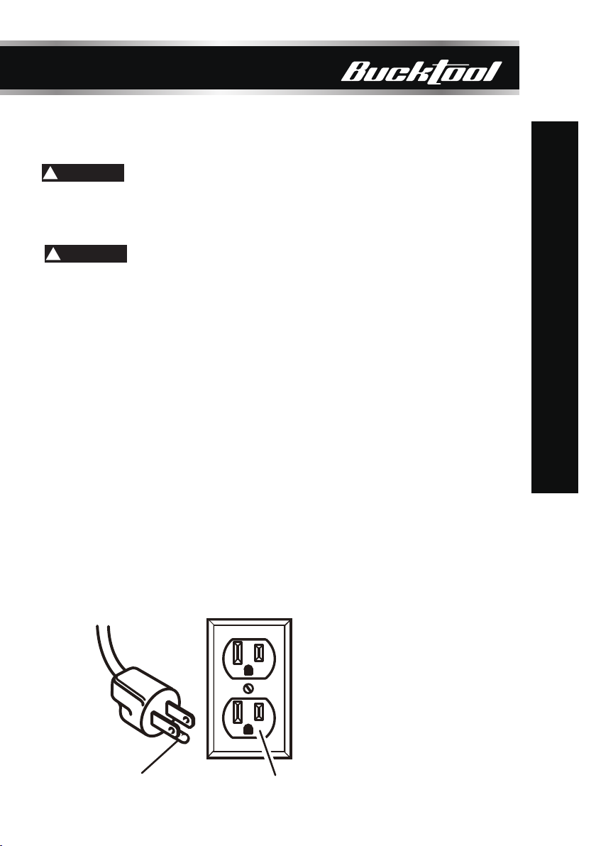
GROUND ALLTOOLS.If tool is equipped with three-prong plug, it should be plugged
into a three-hole electrical receptacle.
USE ONLY CORRECT ELECTRICAL DEVICES: 3-wire extension cords that have
3-prong grounding plugs and 3-pole receptacles that accept the tool’s plug.
KEEP TOOL DRY, CLEAN, AND FREE FROM OIL AND GREASE. Always use
a clean cloth when cleaning. Never use brake fluids, gasoline, petroleum-based
products, or any solvents to clean tool.
NEVER START A TOOL WHEN ANY ROTATING COMPONENT IS IN CONTACT
WITH THE WORKPIECE.
DO NOT OPERATE A TOOL WHILE UNDER THE INFLUENCE OF DRUGS,
ALCOHOL, OR ANY MEDICATION.
WHEN SERVICING use only identical replacement parts. Use of any other parts
may create a hazard or cause product damage.
USE ONLY RECOMMENDED ACCESSORIES listed in this manual or addendums.
Use of accessories that are not listed may cause the risk of personal injury .
Instructions for safe use of accessories are included with the accessory.
extension cords with approved ground connection that are intended for use
outdoors and so marked.
SPECIFIC SAFETY RULES
KEEP BITS CLEAN AND SHARP. Sharp bits minimize stalling. Dirty and dull
bits may cause misalignment of the material and possible operator injury.
KEEP HANDS AWAY FROM WORK AREA. Keep hands away from the bit.
Restrain any loose clothing, jewelry, long hair, etc., that may become entangled
in the bit.
6
DP12VL
SAFETY GUIDELINES
ALWAYS CLAMP WORKPIECE OR BRACE AGAINST COLUMNTO PREVENT
ROTATION. Never use your hand to hold the object while drilling.
USE RECOMMENDED SPEED FOR DRILL ACCESSORY AND WORKPIECE
MATERIAL.
BE SURE DRILL BIT OR CUTTING TOOL IS SECURELY LOCKED IN THE
CHUCK.
BE SURE CHUCK KEY IS REMOVED from the chuck before connecting to
power source or turning power ON.
ADJUST THE TABLE OR DEPTH STOP TO AVOID DRILLING INTO THE
TABLE. Shut off the power, remove the drill bit, and clean the table before
leaving machine.
AVOID DIRECT EYE EXPOSURE when using the laser guide.
ALWAYS ENSURE THE LASER BEAM IS AIMED AT A SURFACE WITHOUT
REFLECTIVE PROPERTIES. Shiny reflective materials are not suitable for
laser use.
NEVER PLACE YOUR FINGERS IN A POSITION WHERE THEY COULD
CONTACT THE DRILL or other cutting tool if the workpiece should
unexpectedly shift.
NEVER PERFORM ANY OPERATION by moving the head or table with
respect to one another. Do not turn the motor switch ON or start any operation
before checking that the head and table support lock handle is clamped tight
to column and head and table support collars are correctly positioned.
BEFORE ENGAGING THE POWER SWITCH, MAKE SURE THE BELT
GUARD IS DOWN AND THE CHUCK IS INSTALLED PROPERLY.
LOCK THE MOTOR SWITCH OFF WHEN LEAVING THE DRILL PRESS. Do
not perform layout, assembly, or set-up work on the table while the cutting
tool is rotating, switched on, or connected to a power source.
IF THE POWER SUPPLY CORD IS DAMAGED, it must be replaced only by
the manufacturer or by an authorized service center to avoid risk.
SAVE THESE INSTRUCTIONS. Refer to them frequently and use to instruct
WARNING
!
other users. If you loan someone this tool, loan them these instructions also.
This product and some dust created by power sanding, sawing, grinding, drilling,
and other construction activities may contain chemicals, including lead, known
to the State of California to cause cancer, birth defects, or other reproductive
harm. Wash hands after handling.
7
SAFETY GUIDELINES
DP12VL
Some examples of these chemicals are:
.
Your risk from exposure to these chemicals varies, depending on how often you
do thistype of work. To reduce your exposure, work in a well-ventilated area and
with approved safety equipment, such as dust masks that are specially designed
to filter out microscopic particles.
**Ampere rating (on tool faceplate )
Cord Length Wire Size (A.W.G.)
Use only 3-wire extension cords that have 3-prong grounding plugs and 3-pole
receptacles that accept the tool’s plug. When using a power tool at a considerable
distance from the power source, use an extension cord heavy enough to carry the
current that the tool will draw. An undersized extension cord will cause a drop in line
voltage, resulting in a loss of power and causing the motor to overheat. Use the
chart provided below to determine the minimum wire size required in an extension
cord. Only round jacketed cords listed by Underwriter’s Laboratories (UL) should
be used.
25' 16 16 16 16 14 14
0-2.0 2.1-3.4 3.5-5.0 5.1-7.0 7.1-12.0 12.1-16.0
EXTENSION CORDS
50' 16 16 16 14 14 12
100' 16 16 14 12 10 —
**Used on 12 gauge - 20 amp circuit.
NOTE: AWG = American Wire Gauge
When working with the tool outdoors, use an extension cord that is designed for
outside use. This is indicated by the letters “W-A” or “W” on the cord’s jacket.
SAFETY GUIDELINES
8
DP12VL
WARNING
!
Before using an extension cord, inspect it for loose or exposed wires and cut or
worn insulation.
Keep the extension cord clear of the working area. Position the cord so that it will
not get caught on lumber, tools or other obstructions while you are working with a
power tool. Failure to do so can result in serious personal injury.
Check extension cords before each use. If damaged replace immediately. Never
use tool with a damaged cord since touching the damaged area could cause
electrical shock resulting in serious injury.
WARNING
!
This tool is powered by a precision built electric motor. It should be connected to a
power supply that is 120 volts, AC only (normal household current), 60 Hz. Do not
operate this tool on direct current (DC). A substantial voltage drop will cause a loss of
power and the motor will overheat. If the tool does not operate when plugged into an
outlet, double check the power supply.
The no-load speed of this tool is approximately 2,800 rpm. This speed is not constant
and decreases under a load or with lower voltage. For voltage, the wiring in a shop is
as important as the motor’s horsepower rating. A line intended only for lights cannot
properly carry a power tool motor. Wire that is heavy enough for a short distance will
be too light for a greater distance. A line that can support one power tool may not be
able to support two or three tools.
ELECTRICAL CONNECTION
SPEED AND WIRING
GROUNDING INSTRUCTIONS (FIG. 1)
Fig. 1
AB
9DP12VL
In the event of a malfunction or breakdown, grounding provides a path of least
resistance for electric current to reduce the risk of electric shock. This tool is
equipped with an electric cord having an equipment-grounding conductor and a
grounding plug. The plug must be plugged into a matching outlet that is properly
installed and grounded in accordance with all local codes and ordinances.
Do not modify the plug provided. If it will not fit the outlet, have the proper outlet
installed by a qualified electrician. Improper connection of the equipment-grounding
conductor can result in a risk of electric shock. The conductor with insulation
having an outer surface that is green with or without yellow stripes is the equipment-
grounding conductor. If repair or replacement of the electric cord or plug is necessary,
do not connect the equipment-grounding conductor to a live terminal.
Check with a qualified electrician or service personnel if the grounding instructions
are not completely understood, or if in doubt as to whether the tool is properly
grounded.
Repair or replace a damaged or worn cord immediately.
This tool is intended for use on a circuit that has an outlet like the one shown in
Figure 1. It also has a grounding pin like the one shown.
SAFETY GUIDELINES
10
DP12VL
PACKAGE CONTENTS
No. Description Qty.
1Head Assembly 1
2Column Assembly 1
3Work Table 1
4Base 1
5Chuck Arbor 1
6Chuck 1
7Chuck Key
Table Lock Handles
1
2
8
Hex Head Bolts 4
Package contents
9
Table Crank Handle 1
10
Hex Wrenches (3mm & 4mm) 2
12
11
Feed Handles 3
13 Speed Handle 1
14 Wedge 1
1
2
34
56 7 8910 11
12
14
13
11 DP12VL
KEY PARTS DIAGRAN
Laser switch
Power switch
Emergency stop
button
LED panel
Chuck
Motor
Rall
Table crank
handle
Feed handle
Pulley cover
Work table
Base
LED light switch
Key parts diagram
12
DP12VL
OPERATING INSTRUCTIONS
UNPACKING
WARNING
!
TOOLS NEEDED
The following tools (not included or drawn
to scale) are needed for assembly:
This product requires assembly.
1. Carefully remove the tool and any accessories from the box. Place it on a level
work surface.
NOTE: This tool is heavy. To avoid back injury, lift with your legs, not your back,
and get help when needed.
Do not use this product if any parts on the Loose Parts List are already assembled
to your product when you unpack it. Parts on this list are not assembled to the
product by the manufacturer and require customer installation. Use of a product
that may have been improperly assembled could result in serious personal injury.
2. Inspect the tool carefully to make sure no breakage or damage occurred
uring shipping.
3. Do not discard the packing material until you have carefully inspected the tool,
identified all loose parts, and satisfactorily operated the tool.
If any parts are damaged or missing, do not operate this tool until the parts are
replaced. Use of this product with damaged or missing parts could result in serious
personal injury.
Do not attempt to modify this tool or create accessories not recommended for
use with this tool. Any such alteration or modification is misuse and could result
in a hazardous condition leading to possible serious personal injury.
supply until assembly is complete. Failure to comply
starting and possible serious personal injury.
WARNING
!
WARNING
!
B
A
C
A. Mallet or hammer
B. Adjustable wrench
C. Phillips screwdriver
13 DP12VL
OPERATING INSTRUCTIONS
WARNING
!
ATTACHING COLUMN TO BASE
1. Place the column assembly (1) on the base (2),
aligning the column support holes to the base
holes.
2. Install a hex head bolt (3) in each column
support hole and tighten bolts using the
adjustable wrench (not included).
TABLE TO TABLE SUPPORT BRACKET
DRILL PRESS HEAD TO COLUMN
1. Place the crank handle (1) onto the shaft (2)
of the table bracket so the flat of the shaft is
under the set screw (3). Tighten the set screw.
2. Thread the table lock handle (4) into the front
of the table support bracket.
3. Thread the table support lock handle into the
rear of the table support bracket (not shown).
4. Position the table (5) in the same direction as
the base. Install the table and tighten the table
lock handle (4) and support lock handle.
1. Carefully lift the drill press head assembly (1)
and position it over the column (2).
2. Place the mounting opening (3) on the drill
press head over the top of the column. Make
sure the drill press head is seated properly
on the column.
3. Align the direction of the drill press head with
the direction of the base and the table.
4. Tighten the set screw (4) using the included
hex wrench.
The drill press head is heavy. To avoid
injury, two people should lift it into position.
1
5
4
3
1
1
2
4
3
2
3
2
14
DP12VL
OPERATING INSTRUCTIONS
FEED HANDLES
1. Insert the three feed handles (1) into the
threaded openings on the feed hub (2).
2. Manually tighten the handles into the
openings. Use an adjustable wrench
(not included) to grip the flats on the
handles and fully tighten them.
NOTE: When using the drill press, one or
two of the feed handles may be removed
if an unusually-shaped workpiece
interferes with the handle rotation.
SPEED HANDLE
INSTALL THE CHUCK
1. Insert the speed handle (1) into the threaded
opening on the speed hub (2).
2. Manually tighten the handle into the openings.
Use an adjustable wrench (not included) to
grip the flats on the handles and fully tighten
them.
1. Inspect and clean the taper hole in the chuck
(1) and the spindle (2). Remove all grease,
coatings, and particles from the chuck and
spindle surfaces with a clean cloth.
2. Open the chuck jaws (3) by manually turning
the chuck barrel clockwise. Make sure the
jaws are completely recessed inside the chuck.
3. Insert the chuck arbor (4) into the opening at
the top of the chuck.
4. Insert the arbor into the spindle. Rotate it until
the tang of the arbor (the flats on the end) is
aligned with the slot in the spindle, and the chuck
and arbor can be pushed upwards. Seat the chuck by placing a block of wood
(not included) below the chuck and firmly tapping the wood once with a hammer.
Alternatively, firmly tap the chuck once with a rubber mallet or dead-blow hammer
(not included).
5. If the chuck or arbor fail to seat properly, they may not be clean enough. Remove
them and thoroughly clean the mating surfaces, then try again. Ensure all dust,
debris, and liquids are removed from the surfaces, and that neither surface is damaged.
1
2
2
1
2
4
1
3
15 DP12VL
OPERATING INSTRUCTIONS
MOUNTING THE DRILL PRESS
If the drillpss is to be used in a permanent location secu it to a workbench or other
stable surface.
If the drill press is to be used as a portable tool,fasten it permanently to a mounting
board that can easily be clamped to a workbench or other stable surface.The
mounting board should be of sufficient size to avoid tipping while drill press
is in use. Any good grade plywood or chipboarwith a 3/4
in. thi ckness is
recommended.
1. Mark holes on surface where drill
press is to be mounted using holes
in drill press base as a template for
hole pattern.
2. Drill holes through mounting surface.
3. Place drill press on mounting surface,
aligning holes in the base with holes drilled in the mounling surface.
4. Insert bolts (not included) and tighten securely with lock washers and hex
nuts (not included).
5. If lag bolts are used,make sure they are long enough to go through holes
in drill press base and material the
drill press is being mounted to. If
machine bolts are used make sure bolts are long enough to go through holes
in drill press,the material being mounted to,and the lock washers and hex nuts.
NOTE: AII bolts should be inserted from the top. Install the lock washers and hex
nuts from the underside of the workbench.
Once the drill press is secureIy mounted on a sturdy surface:
vibration when the motor is switched ON.
Adjust andretighten the mounting
hardware as necessary.
Check to assure that the spindle shaft
Check the table assembly to assure smooth movement up and down the column.
moves smoothly.
INSTALLING A DRILL BIT
1. Place the chuck key (1) into the side keyhole
of the chuck (2), meshing the key with the
gear teeth.
2. Turn the chuck key counterclockwise to open
the chuck jaws (3).
3. Insert a drill bit (4) into the chuck far enough
to obtain the maximum grip of the chuck jaws
on the bit shank.
4. Center the drill bit in the chuck jaws before the final tightening of the chuck.
5. Tighten the chuck jaws using the chuck key to ensure that the drill bit will not slip
while drilling. Tighten all three keyholes on the chuck.
6. Remove the chuck key and place it back on the onboard storage.
1
4
3
2
16
DP12VL
OPERATING INSTRUCTIONS
RAISE OR LOWER THE TABLE
1. Loosen the support lock handle (1) and
turn the crank handle (2) until the table is
at the desired height.
2. Tighten the support lock handle before drilling.
TILT THE TABLE
1. Loosen the bevel lock bolt (1) by turning it
counterclockwise with an adjustable wrench
(not included).
2. Tilt the table to the desired angle, using the
bevel scale (2) as a basic guide.
3. Re-tighten the bevel lock bolt.
ADJUSTING THE LASER
1. Place a workpiece on the table.
2. Turn the laser switch (1) to the ON position.
3. Lower the drill bit to meet the workpiece.
The two laser lines should cross where the
drill meets the workpiece.
4. If the laser needs to be adjusted:
a. Using the included 3 mm hex key, turn the
laser adjustment set screws (2) counterclockwise.
There is one of each side of the head.
b. Rotate the laser light housing (3) until the two
laser lines intersect where the drill meets the
workpiece.
5. Re-tighten the adjustment set screws (2).
DEPTH ADJUSTMENT
1. Slightly loosen the depth adjustment knob (1)
anticlockwise.
2. Rotate the feed handle (2) to lower the drill bit
to the required depth, until the pointer (3) aligns
with the desired value on the depth scale.
3. To set the drilling depth, tighten the depth
adjustment knob (1) clockwise. Return the feed
handle (2) to its initial position afterwards.
1
1
1
2
1
3
2
3
2
2
DP12VL
OPERATING INSTRUCTIONS
17
SPEED ADJUSTMENT
1. Turn the belt tension handle (1) upward to
increase the belt speed.
2. Turn the belt tension handle (1) downward
to decrease the belt speed.
3. Read the actual speed displayed on the
LED panel (2).
SWITCHING ON/OFF
1. Turn the emergency STOP button (1)
clockwise to release it, if it has already
been activated.
2. Switch the product on by pressing the
green ON button I (2) and wait until the
drill bit has reached maximum speed.
3. Switch the product off by pressing the
red Off button O (3) or pressing the
emergency STOP button (1) in an
emergency.
REMOVE THE CHUCK
1. Turn the feed handles (1) to lower the
chuck (2) to the lowest position.
2. Insert the drift key (3) into the opening in
the quill. Gently tap on the wedge using a
rubber mallet (not included). The chuck
and arbor will drop out.
NOTE: To avoid possible damage to the drill
or chuck, be prepared to catch the chuck as it falls.
1
1
1
2
3
2
3
2
High
Speed
Low
Speed
DRILL BIT SIZE RECOMMENDATIONS
RPM Wood Aluminum, Zinc, Brass Iron, Steel
2000 to 3200 3/8 in. 9.5 mm 7/32 in. 5.6 mm 3/32 in. 2.4 mm
1400 to 2000 5/8 in. 16 mm 11/32 in. 8.75 mm 5/32 in. 4 mm
1000 to 1400 7/8 in. 22 mm 15/32 in. 12 mm 1/4 in. 6.4 mm
800 to 1000 1-1/4 in. 31.75 mm 11/16 in. 17.5 mm 3/8 in. 9.5 mm
580 to 800 1-5/8 in. 41.4 mm 3/4 in. 19 mm 5/8 in. 16 mm
18
DP12VL
OPERATING INSTRUCTIONS
REPLACING THE BELT
SPINDLE RETURN SPRING
The spindle is equipped with an auto-return mechanism. The main components are a
spring and a notched housing. The spring was properly adjusted at the factory and
should not be readjusted unless absolutely necessary.
1. Unplug the drill press.
2. Loosen the two housing nuts (1) approximately
1/4" (6 mm). Do not remove the nuts from the
threaded shaft. Do not allow the spring or spring
housing to slip out of control.
3. While firmly holding the spring housing (2),
carefully pull spring housing out until it clears
the raised stop (3).
4. Turn the housing so that the next notch (4)
is engaged with the raised stop (3).
• To increase the spindle return tension, turn the spring housing counter-clockwise.
• To decrease the tension, turn the spring housing clockwise.
5. Tighten the two housing nuts. Do not overtighten the two nuts. If the nuts are
tightened too much, the movement of the spindle and feed handles will become
sluggish.
Belt tension and drill press speed is controlled by automatic adjustments made to the
diameter of the front spindle when the speed handle is moved.
1. Plug in the drill press and turn it ON. Adjust
the speed to the highest setting, then turn the
drill press OFF and unplug it.
2. Open the belt cover, remove the Phillips-head
screw from the right side, then open the lid.
3. Press down on the bottom side of the motor
pulley (2). This will loosen the belt tension.
Work the belt (1) off the pulleys.
4. Place the new belt on the motor pulley (1), then press down on the bottom side of the
pulley as before and get the belt as close to the motor shaft as possible. Make sure
the bottom side of the pulley is pushed fully downward.
5. Work the belt around the spindle pulley (3). The belt will not be taut, but will self-seat
later.
6. Close and secure the belt cover.
7. Plug in and turn ON the drill press. The belt will self-seat and achieve proper tension
on its own.
2
3
1
1
2
3
4
DP12VL
19
OPERATING INSTRUCTIONS
DRILLING METAL
• Use metal-piercing twist drill bits.
• It is always necessary to lubricate the tip of the drill with oil to prevent overheating of
the drill bit.
• All metal workpieces should be clamped down securely. Any tilting, twisting, or shifting
causes a rough drill hole, and increases the potential of drill bit breakage.
• Never hold a metal workpiece with your bare hands. The cutting edge of the drill bit
may seize the workpiece and throw it, causing serious injury. The drill bit will break if
the metal piece suddenly hits the column.
• If the metal is flat, clamp a piece of wood under it to prevent turning. If it cannot be
laid flat on the table, then it should be blocked and clamped.
DRILLING WOOD
• Brad point bits are preferred. Metal piercing twist bits may be used on wood.
• Do not use auger bits. Auger bits turn so rapidly that they can lift the workpiece off
of the table and whirl it around.
• Always protect the drill bit by positioning the table so that the drill bit will enter the
center hole when drilling through the workpiece.
• To prevent splintering, feed the drill bit slowly right as the bit is about to cut through
to the backside of the workpiece.
• To reduce splintering and protect the point of the bit, use scrap wood as a backing
or a base block under the workpiece.
FEEDING THE DRILL BIT
• Pull down on the feed handles with only enough force to allow the drill bit to cut.
• Feeding too rapidly might stall the motor, cause the belt to slip, damage the workpiece,
or break the drill bit.
• Feeding too slowly will cause the drill bit to heat up and burn the workpiece.

Other Bucktool Power Tools manuals

Bucktool SCM4500 User manual

Bucktool

Bucktool SCM4500 User manual

Bucktool SCM8080 User manual

Bucktool

Bucktool SCM8080 User manual

Popular Power Tools manuals by other brands

Magma D & R manual

Magma

Magma D & R manual

Proxxon MICRO-Router MOF owner's manual

Proxxon

Proxxon MICRO-Router MOF owner's manual

NAVAC NEF6LM user manual

NAVAC

NAVAC NEF6LM user manual

Synthes ComPact Air Drive II Instructions for use

Synthes

Synthes ComPact Air Drive II Instructions for use

Eastsign SOT-64 user manual

Eastsign

Eastsign SOT-64 user manual

DeWalt XR LI-ION DCS491 manual

DeWalt

DeWalt XR LI-ION DCS491 manual

Bullet tools Magnum 626 user guide

Bullet tools

Bullet tools Magnum 626 user guide

Atlas Copco EP12XS HR13 Product instructions

Atlas Copco

Atlas Copco EP12XS HR13 Product instructions

Orgapack H-1334 manual

Orgapack

Orgapack H-1334 manual

Hitachi WR 18DBDL2 instruction manual

Hitachi

Hitachi WR 18DBDL2 instruction manual

Meec tools 029-062 Operating instructions in original

Meec tools

Meec tools 029-062 Operating instructions in original

EINHELL DSL 250/2 Original operating instructions

EINHELL

EINHELL DSL 250/2 Original operating instructions

DeWalt DW890 instruction manual

DeWalt

DeWalt DW890 instruction manual

Sefa LP 130 V3 user guide

Sefa

Sefa LP 130 V3 user guide

Makita DCG140 instruction manual

Makita

Makita DCG140 instruction manual

DeWalt DCS367N Original instructions

DeWalt

DeWalt DCS367N Original instructions

AREBOS AR-HE-MF17000W user manual

AREBOS

AREBOS AR-HE-MF17000W user manual

Yokota E-M700 manual

Yokota

Yokota E-M700 manual

manuals.online logo
manuals.online logoBrands
  • About & Mission
  • Contact us
  • Privacy Policy
  • Terms and Conditions

Copyright 2025 Manuals.Online. All Rights Reserved.