8
Again, as you practice riding the Buddy Bike in a safe place, like an empty school playground,
try stopping at various speeds, say at 5, 10 and 15 miles per hour. Note how many feet it
takes to stop at each of these speeds. Use the captain’s brakes, then use those plus the
stoker’s brake. Then use this information to keep your speed under control. Go slower in traf-
fic, for example, where you may have to make a sudden, unexpected stop. Look as far ahead
as possible, be alert as you approach parking lot driveways, children and others on foot, bicy-
cles, skate boards or roller blades. Watch out for school and other buses approaching a stop.
When you come to a stop, both captain and stoker should extend one foot to the ground, and
then both feet if you have to wait for a stoplight. Remember, on downhill runs, gravity
alone may propel the Buddy Bike to an unsafe speed.
Use both captain’s and stoker’s brakes to slow or to stop on a downhill ride. On the flats, the
captain can usually control speed by applying both brake levers. Apply the rear brake lever
first, then the front brake lever. On downhill runs, or to make an emergency stop, the stoker
should also apply the drum brake lever, as the captain applies both his/her brakes. Again,
both riders should practice braking on the flats and on downhill runs until you both are thor-
oughly familiar with the excellent braking power and speed control of the Buddy Bike’s
brakes.
Remember, when it’s raining, your brakes, good as they are, will lose some stopping
power. It will take longer to stop when wheel rims are wet. In wet conditions, apply
brakes sooner than you would in dry conditions. Both captain and stoker should use
both sets of brakes, even at low speeds. Reduce speed in wet weather, watch out for
an accumulation of wet leaves in the fall, they can be very slippery.
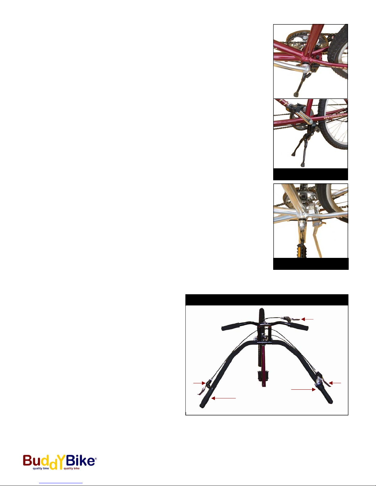
How and When to Shift Gears
7-Speed Buddy Bike Family (BB102-AL)
Buddy Bike Family is equipped with the Shimano’s NEXUS
INTER 7. It can shift to any gear anytime, even at a stop. To
shift, simply rotate the gripshift on the right of the captain’s
handlebar, “A” in Figure 5. The 7 speed gear combinations
gives you a wide range of choices for easy pedaling. By turn-
ing the gripshift toward you, select gear 6 or 7 for pedaling
downhill. While on level roads or paths use gears 3, 4 or 5.
Upon pedaling uphill, turn the gripshift away from you to gear
1 or 2. By selecting the proper gear, you can make pedaling
comfortable and easier for both riders.
24-Speed Buddy Bike Sport (BB103-AL)
Buddy Bike Sport is equipped with the Shimano’s NEXAVE
C530 INTEGO 24 speed (8 external, 3 internal hub). The 3
internal gears can shift to any gear at anytime, even at a stop.
However, this bike includes a derailleur and it would be best
to shift all gears while pedaling. To shift the internal gears,
push the lever marked “LOW” or “HIGH” on the left side of the
captain’s handlebar (Figure 6A). To shift the external gears,
push the lever marked “LOW” or “HIGH” on the right side of
the captain’s handlebar (Figure 6B).
Figure 6B
Figure 6A