1. Overview
1.1 Introduction
The No-Cascading new CAN Fiber Optic Converter is a multi-master and high
performance Field bus Control System (FCS). The modular fiber optic transmission
system can be used to transmit CAN-based bus systems such as DeviceNet or
CANOpen via fiber optics data interfaces over a pair of multi mode or single mode
optical fibers. Our FMC Fiber Optic Converter uses the fiber cable as its transmission
medium and utilizes Optical Fiber modulation/demodulation technology to changes the
electric medium into a light medium transmission.
The Fiber Optic Converter product eliminates many of the disadvantages of copper
cable. Examples of these disadvantages are EMI/RFI, ground loops (electrical isolation
with fiber), high attenuation (high signal loss), short transmission distance between
nodes of a system, and potential lightning damage.
The Fiber Optic Converter can be widely used, such as Industrial Controls, Intelligent
Transportation Systems (ITS), Industrial Networking, Supervisory Control and Data
(SCADA) and so on.
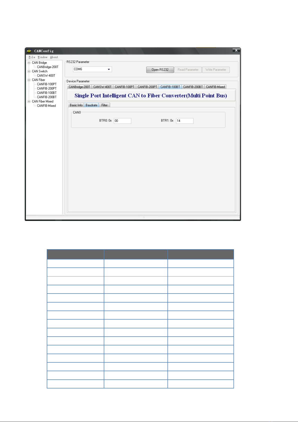
1.2 Technical Specification
CAN BUS
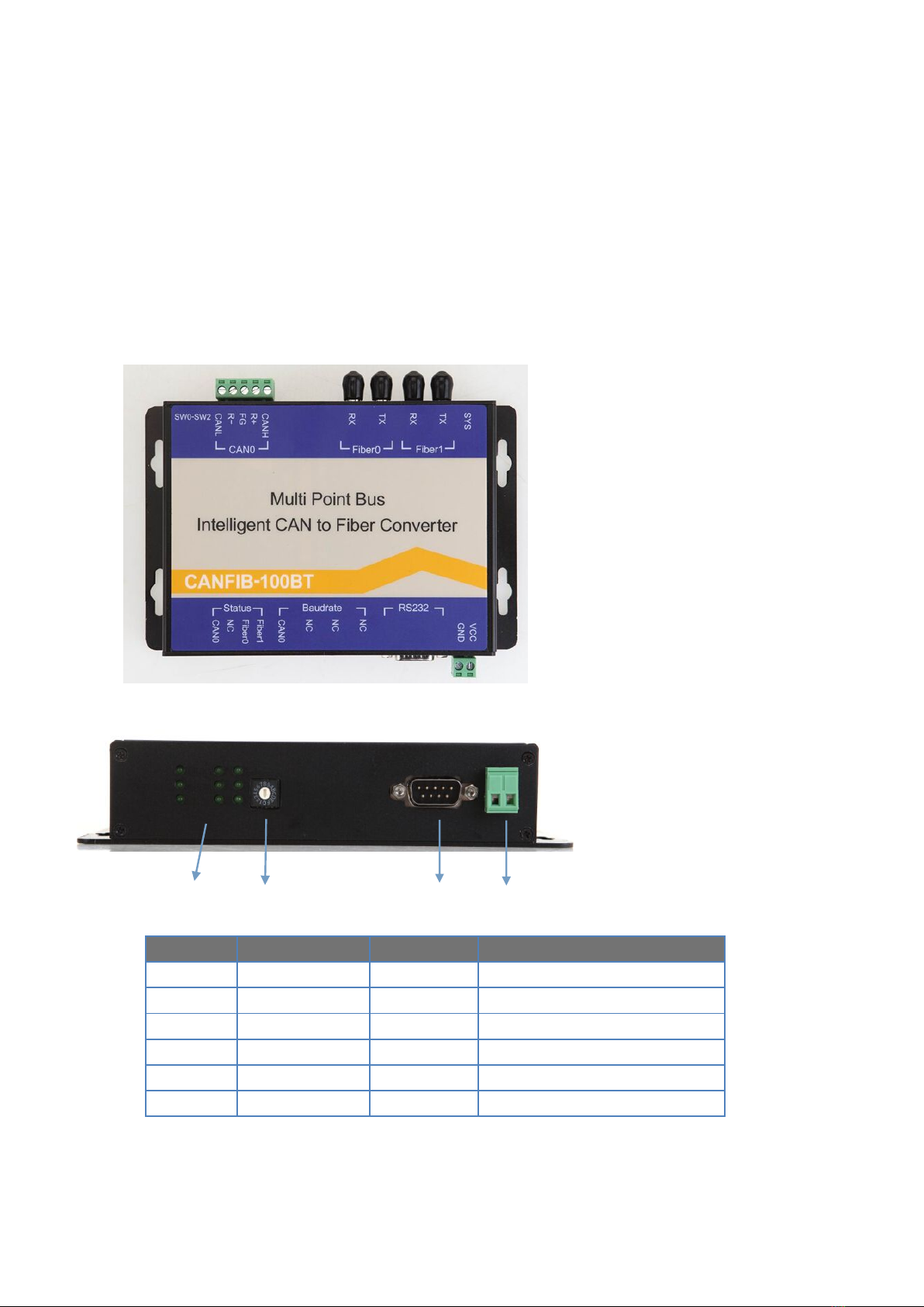
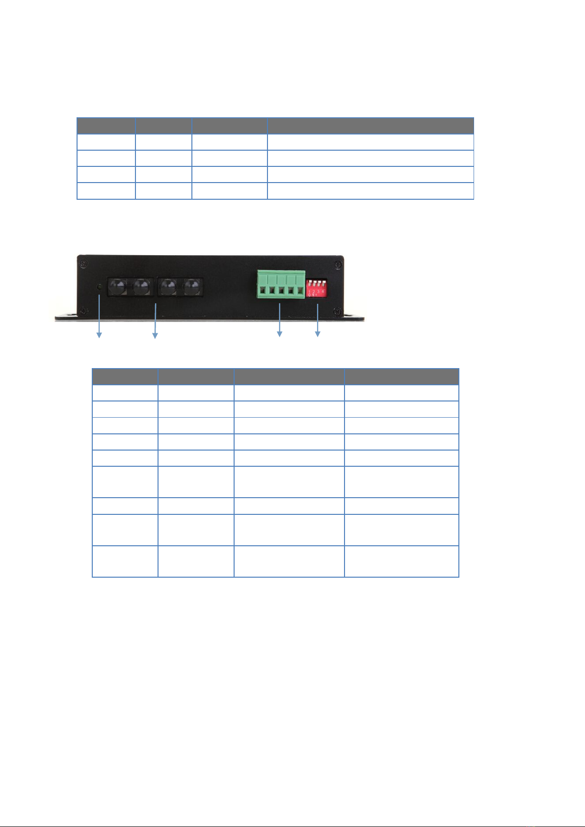
Connectors Block Terminal
Standard CAN1.0, CAN2.0
Data Rate DC0-1Mbps
Extended Distance SM:0~20Km MM:0~2Km
OPTICAL
Number of Fibers 4
Wavelength 1310/1550nm(SM), 850/1310nm(MM)
Fiber Type 62.5/125µm(MM), 9/125µm(SM)
Distance 0 ~ 2Km(MM) , 0~20 Km(SM)
Connector Type ST/PC or SC/FC as options
GENERAL
Operating Temperature -30~ 70˚C / -30 ~ +158ºF
Operating Humidity 0 ~ 95% non-condensing
Mean Time Between Failure (MTBF) > 70,000hrs
Power Supply Adaptor DC 9~40V
Dimensions (H ×L×W) 112(H)×147(W)×36(D)MM