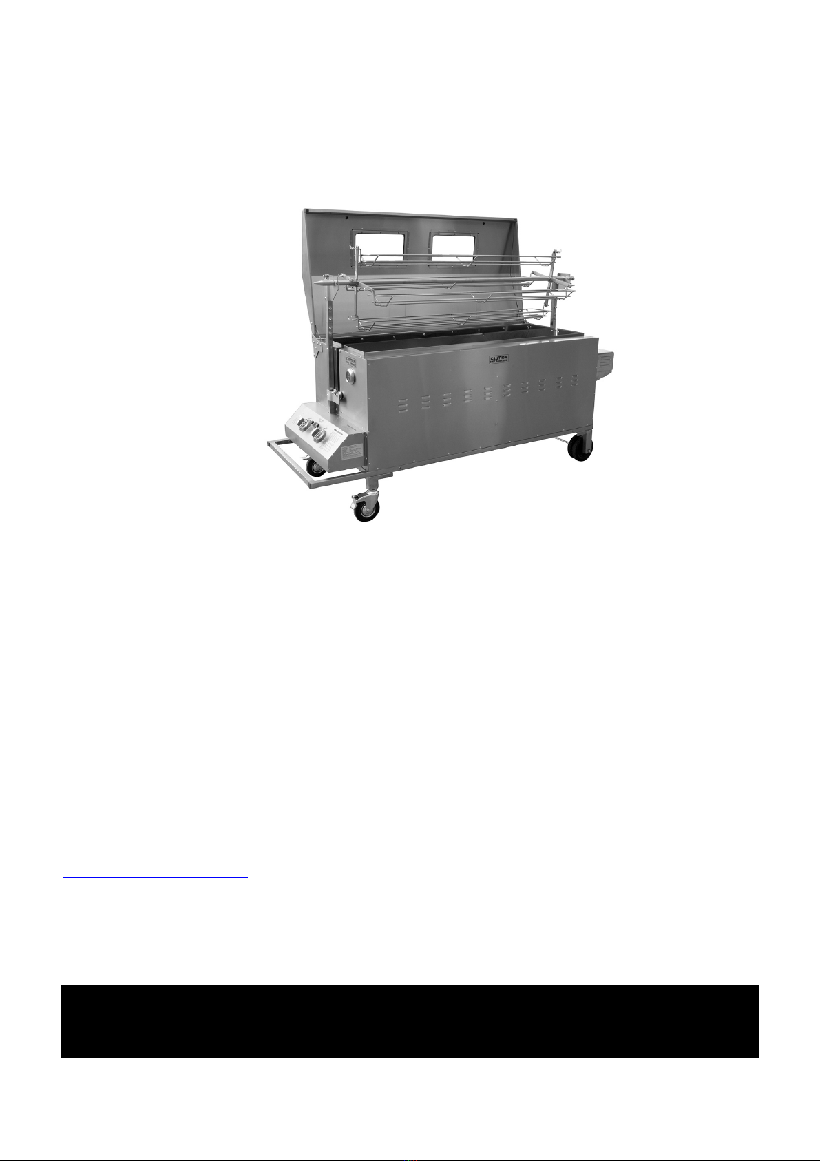
Buffalo Tools BPROASTER User manual

BPROASTER
DELUXE PIG ROASTER
ASSEMBLY INSTRUCTIONS
READ ALL INSTRUCTIONS AND WARNINGS BEFORE USING THIS PRODUCT.
This manual provides important information on proper operation & maintenance. Every effort has been
made to ensure the accuracy of this manual. These instructions are not meant to cover every possible
condition and situation that may occur. We reserve the right to change this product at any time without
prior notice.
IF THERE IS ANY QUESTION ABOUT A CONDITION BEING SAFE OR UNSAFE,
DO NOT USE THIS PRODUCT!
DO NOT RETURN THIS PRODUCT TO THE RETAILER - CONTACT CUSTOMER
SERVICE FIRST.
If you experience a problem, have questions or need parts for this product, visit our website
http://www.buffalotools.com or call Customer Service at 1-888-287-6981, Monday-Friday, 8 AM - 4 PM
Central Time. A copy of the sales receipt is required.
KEEP THIS MANUAL, SALES RECEIPT & APPLICABLE WARRANTY FOR FUTURE
REFERENCE
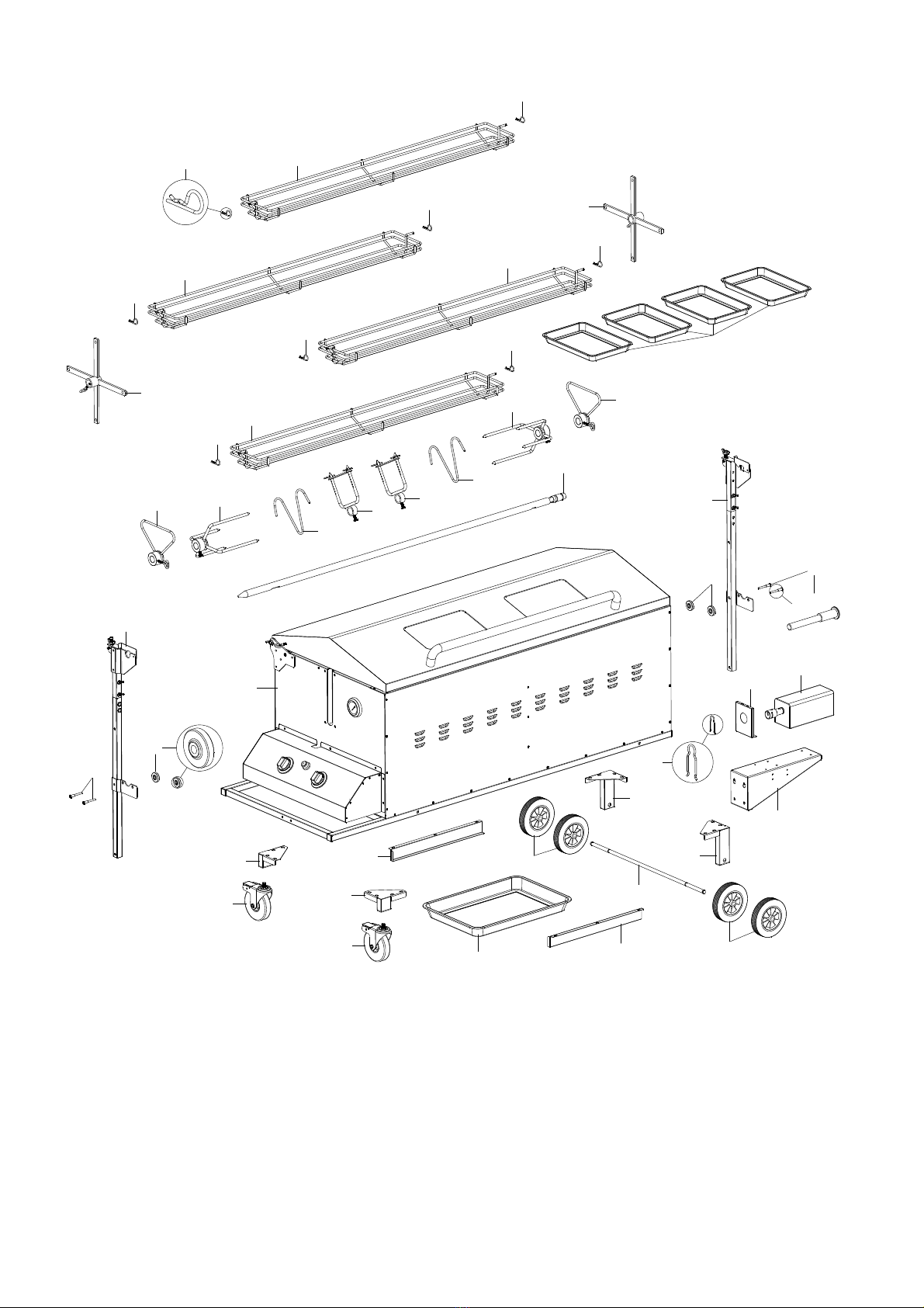
ATTENTION: Assembly of this oven involves many large components. It
is advisable to have two people assemble the unit.

Page 2 of 11
ASSEMBLY CHECKLIST
Read all instructions thoroughly before proceeding. Find a large, clean area in which to assemble your
oven. Refer to the parts list and assembly diagram as necessary. Assembly of this oven involves many
large components. It is advisable to have two people assemble the unit.
Tools required: A Philips crosshead or flat-bladed screwdriver and either a spanner or a pair of pliers.
NOTICE: Make sure all the plastic protection (usually a blue film) is removed before assembling!
INCLUDED ACCESSORIES
CONFIGURATIONS
Configure with
Rotisserie Shelf
Configure as
Slow Roaster

Page 3 of 11
21
3
6
5
7
11
9
10
12
13
14
15
16
1
1
1
2
2
2
2
2
2
2
3
4
5
6
8
8
7
11
12
17
18
19
20
22
21
24
23
17 18
25
27
4
26
PARTS DIAGRAM

Page 4 of 11
PARTS AND HARDWARE LIST
Ref
Description
QTY
1
Roast cradle
4
2
R Clip
8
3
Roast cradle support
2
4
Cooking Pans/Drip Pan
5
5
Triangle support
2
6
Meat prong
2
7
W Retainer
2
8
U-Shaped fork assembly
2
9
Rotisserie shaft
1
10
Rotisserie shaft front bracket assembly
1
11
Roller bolt
4
12
Roller
4
13
Spit roaster body (with glass windows)
1
14
Rotisserie shaft rear bracket assembly
1
15
Wheel support-front left assembly
1
16
Wheel support-front right assembly
1
17
Wheel-5” with brake
2
18
Wheel-6” without brake
2
19
Wheel axle
1
20
Wheel support-back left assembly
1
21
Wheel support-back right assembly
1
22
Spit To Motor Connector (U-Shape Pin)
1
23
Motor heat shield panel
1
24
Motor
1
25
Motor support
1
26
Drip tray brace-right
1
27
Drip tray brace-left
1
A
M5×10 Screw
2
B
M6×12 Screw
8
C
M6×35 Screw
4
D
M8×15 HEX Screw
16
E
¢6 Lock Washer
4
F
¢6 Flat Washer
4
G
¢13 Flat Washer
8
H
Split Lock Washer
4
I
M6 Nut
4

Page 5 of 11
1) Remove straps and box
lid. Sides will start to
come apart.
2) Remove accessories
from box, and remove the
protective wrap which is
covering the pig roaster.
3) Remove the box that is
stored inside the pig roaster.
ASSEMBLY
4) Place a blanket or cardboard
on the ground to protect the
stainless steel, then rotate or flip
roaster upside down to install
wheels.
5) Locate the swivel wheels
(#17) (5” with brake) and mount
them to the front side with the
thermostat.
6) Make sure both wheels
are securely attached on
either side of roaster.
Open all boxes and remove
hardware. Set empty boxes
aside, do not discard until
Pig Roaster is assembled.
Identify all parts with
diagram and list before
beginning assembly.

Page 6 of 11
ASSEMBLY (Continued)
8) Refer to the diagram (Upper
Right) for proper placement of
Lock & Flat Washers.
7) Locate and install #20
and #21 wheel supports.
Then install (#18) 6” wheels
without brake on back
end of roaster.
9) Install drip tray brace #26
and #27. The stop end will
stop the drip tray and is
positioned at the Back.
10) Slide the Drip tray onto brace.
11) Note that the illustration
shows the proper position of
the stop end of Drip Tray
brace.
Stop End
Stop End
Placement of Lock & Flat Washers

Page 7 of 11
ASSEMBLY (Continued)
12) Mount #25 motor
support.
13) Install #14 Rear
Bracket Assembly. Note
this has the Square slot.
14) Install the Roller Bolt
and Roller, follow the
photo above.
16) Install #24 motor.
17) Install #23 motor heat
shield.
15) Note the positioning
of the Rollers.
19) Install #10 Rotisserie
shaft bracket assembly.
20) Install the Roller Bolt
and Roller, follow the photo
above.
18) Locate #10 Rotisserie
shaft bracket assembly,
which has round slot.

Page 8 of 11
ASSEMBLY (Continued) Note: The diagrams list the positioning for Washers, Bolts, etc.
21) Attach the regulator hose
(included) located under the
front side (thermostat side).
Ref # B M6×12×6 PCS
Ref # D HEX M8×15×16 PCS
Ref # 15
Ref # 27
Ref # 20
Ref # 16
Ref # 26
Ref # 21
Ref # 13 / 13A

Page 9 of 11
ASSEMBLY (Continued) Note: The diagrams list the positioning for Washers, Bolts, etc.
U-Shape Pin
Ref # 6
Ref # 7
Store U-Shape Pin Here
When Not using Rotisserie
Ref # 9
Ref # 22
Ref # 8
Ref # 7
Ref # 6
Ref # 5
Ref # 5
Ref # 3
Ref # 1
Ref # 2

Page 10 of 11
ASSEMBLY (Continued) Note: The diagrams list the positioning for Washers, Bolts, etc.
Unscrew the igniter cap and insert a
“AA” battery with the “ +“ end upwards.
Ref # 4
Ref # 4
The thermocouple can move during the first cooking process.
Simple repositioning of the probe by altering its position on the
brass thread so it is nearer the flame. (Do not touch the white
porcelain).

Page 11 of 11
ASSEMBLY (Continued)
Familiarise yourself with the Spit To Motor Connector (U-Shape Pin). DO NOT LOSE THIS PIN. You will
find two holes on the motor bracket where this pin can be stored when not in use.
If stored outside, fit a rainproof cover over the oven when it is not in use.
IMPORTANT
Upon receipt, your oven will be covered in a thin layer of oil which is used in the manufacturing process.
This needs removing prior to first use with either hot soapy water or a remover such as white spirit. If you
don’t remove this prior to getting the oven hot on the first occasion, the burnt oil will tarnish the metal,
especially on the inside.
Avoid rubbing the printed ‘HOT’ areas on the oven with thinners or similar agents as they may damage the
printing.
ATTENTION: Due to the heating and cooling of the oven and vibrations caused by the spit
rotations, some of the screws may become loose during transit or use. PLEASE tighten the
screws periodically, in particular the 4 screws on the motor MUST be checked every time
you cook. As these are mounted upside down, they are particularly venerable to becoming
slack and a motor falling off could be a disaster half way through the cooking
process.
Other manuals for BPROASTER
1
Table of contents
Other Buffalo Tools Kitchen Appliance manuals