BUFFALO TURBINE BT-CKB5EFI Parts list manual

1
TABLE OF CONTENTS
Ref. Number
Description
Page Number
1.0
Introduction
2
2.0
Safety
3
2.1
Safety Decals
4
2.2
General Safety
4
2.3
Operating Safety
4
2.4
Maintenance Safety
4
2.5
Transport Safety
5
2.6
Storage Safety
5
2.7
Sign-off Form
5
3.0
Warranty Information
6
3.1
Warranty Registration Form
7
4.0
Operations
8
4.1
To the new operator or owner
8
4.2
Break-in
8
4.3
Pre-Operation Checks
8
4.4
Model BT-CKB5EFI Assembly Instructions
9
4.5
Field Operation
10
4.6
Operating RPM
10
4.7
Storage
10
5.0
Troubleshooting
10
6.0
Machine Specification
11
7.0
Maintenance
12
7.1
Maintenance Safety
12
7.2
Fluids
12
7.3
Service Checklist
12
Moreflex Coupling Parts
13
Moreflex Coupling Installation
14
BT-CKB5EFI Parts Reference (Serial # 24186-25614)
15
BT-CKB5EFI Parts Reference (Serial # 25614-27920)
16
BT-CKB5EFI Parts Reference (Serial # 27921-31740)
17
BT-CKB5EFI Parts Reference (After Serial # 31741)
18
BT-CKB5EFI Parts Sub-Assemblies
19
Bill of Materials for BT-CKB5EFI
20
BT-CKB5EFI Wireless Remote System Manual
21
Wireless system Transmitter Programming
22
Wireless system warranty information
23
Wireless Remote System Diagnostic Tests
24-25
Wiring Schematic for Wireless Remote System
26-27
Wireless system troubleshooting guide
28
Nozzle Options
29
Buffalo Turbine Additional Products
30

2
1.0 INTRODUCTION
Congratulations on your choice of a Buffalo Turbine Debris Blower. This equipment has been designed and manufactured to
meet the needs of the Turf Care Industry.
Safe, efficient and trouble-free operation of your Buffalo Turbine Blower requires that you and anyone else, who will be
operating or maintaining the Blower, read and understand all of the safety, operation, maintenance and troubleshooting
information contained within this Operator’s manual.
This Manual covers the BT-CKB5EFI Turbine Blower.
Keep this manual handy for frequent reference and to pass on to new operators or owners. Call your Buffalo Turbine dealer or
distributor if you need assistance, information, or additional copies of the manuals.
SERIAL NUMBER LOCATION
Always give your dealer the serial number of your Debris Blower when ordering parts or requesting service or other information.
The serial number plate(s) is located where indicated in the pictures below. Please document the number in the space provided for
easy reference.
OPERATOR ORIENTATION –The directions left, right, front and rear, as mentioned throughout the manual, are as seen from
the driver’s seat and facing in the direction of travel.
MODEL BT-CKB5EFI
LEFT FRONT TOP SURFACE OF FRAME
Serial Number: _______________
Serial #

3
2.0 SAFETY
YOU are responsible for the SAFE operation and maintenance of your Buffalo Turbine Debris Blower. YOU must ensure
that you and anyone else, who is going to operate, maintain or work around the Buffalo Turbine Blower be familiar with the
operating and maintenance procedures and related SAFETY information contained in this manual. This manual will take you
step-by-step through your working day and alerts you to all good safety practice while operating the Blower.
Remember YOU are the key to safety. Good safety practices not only protect you but also the people around you. Make these
practices a working part of your safety program. Be certain that EVERYONE operating this machine is familiar with the
procedures recommended and follows safety precautions. Remember most accidents can be prevented. Do not risk injury or
death by ignoring good safety practices.
Blower owners must give operating instructions to operators or employees before allowing them to operate the Blower,
and at least annually thereafter.
The most important safety device on this equipment is a SAFE operator. It is the operator’s responsibility to read and
understand ALL Safety and Operating instructions in the manual and to follow these. All accidents can be avoided.
A person who has not read and understood all operating instructions is not qualified to operate the machine. An untrained
operator exposes themselves and bystanders to possible serious injury or death.
Do not modify the equipment in any way. Unauthorized modification may impair the function and/or safety which could
affect the life of the equipment.
Think SAFETY! Work SAFELY!
This Safety Alert symbol means ATTENTION! BECOME ALERT! YOUR SAFETY IS INVOLVED!
The Safety Alert symbol identifies important safety messages on the Buffalo Turbine Blower and in the manual. When you
see this symbol, be alert to the possibility of personal injury or death. Follow the instructions in the safety message.
SIGNAL WORDS: Note the use of the signal words DANGER, WARNING and CAUTION with the safety messages. The
appropriate signal word for each message has been selected using the following guidelines
1. DANGER –injury or death if the proper precautions are not taken.
2. WARNING -- A specific hazard or unsafe practice that COULD result in severe personal injury or death if proper
precautions are not taken.
3. CAUTION –Unsafe practices that COULD result in personal injury if proper practices are not taken, or as a reminder of
good safety.
The Safety Alert symbol identifies important safety messages on the Buffalo Turbine Blower and in the manual.
When you see this symbol, be alert to the possibility of personal injury or death. Follow the instructions in the
safety message.
Why is SAFETY important to you?
3 Big Reasons: Accidents Disable and Kill
Accidents Cost
Accidents Can Be Avoided

4
2.1 SAFETY DECALS
The types of decals on the blower unit are shown below. Good safety requires that you familiarize yourself with the various
Safety Decals, the type of warning and the area, or particular function related to that area that requires your SAFETY
AWARENESS.* THINK SAFETY! WORK SAFELY!
REMEMBER –If safety decals have been damaged, removed, become illegible or parts replaced without decals, new
decals must be applied. New decals are available from your authorized dealer.
2.2 GENERAL SAFETY
1. Read and understand the Operator’s Manual and all safety signs before operating, maintaining, and adjusting.
2. Provide a first-aid kit for use in case of an accident. Store in a highly visible place.
3. Provide a fire extinguisher for use in case of an accident. Store in a highly visible place.
4. Wear appropriate protective gear. This list includes but is not limited to:
A hard hat
Protective shoes with slip resistant soles
Protective glasses or goggles
Heavy gloves
Wet weather gear
Hearing protection
5. Do not operate without guards or shields properly installed.
6. Do not allow riders.
7. Wear appropriate ear protection for prolonged exposure to excessive noise.
8. (All Models) Set Blower on the ground, stop engine, set park brake, remove ignition key and wait for all moving
parts to stop before dismounting to service or adjust.
9. Clear the area of people, especially small children, before starting the unit.
10. Review all safety related items annually with all personnel who will be operating or maintaining the Blower.
11. Keep hands, feet, hair and clothing away from moving parts. Operate equipment only while seated in the operator’s seat.
2.3 OPERATING SAFETY
1. Read and understand the Operator’s Manual and all safety signs before operating, servicing or adjusting.
2. Before servicing or repairing, Set blower on the ground, stop engine, set park brake, remove key, and wait for all
moving parts to stop.
2.4 MAINTENANCE SAFETY
1. Read and follow ALL general, operating, maintenance and safety information in this manual.
2. Support the machine with blocks or safety stands when changing tires or working beneath it.
3. Set Blower on the ground, stop engine, set park brake, remove ignition key and wait for all moving parts to stop before
operating, servicing or adjusting.
4. Make sure all guards are in place and properly secured when operating or maintaining the Blower.
!ATTENTION!
1. KEEP HANDS, FEET AND CLOTHING AWAY FROM POWER DRIVEN PARTS.
2. STOP ENGINE AND REMOVE KEY BEFORE LEAVING OPERATOR’S POSITION.
3. MACHINE MUST COME TO A COMPLETE STOP BEFORE ANY MAINTENANCE, TO
INCLUDE ADJUSTING, LUBRICATING OR CLEANING, IS PERFORMED.
4. KEEP PEOPLE AND PETS AT SAFE DISTANCE FROM MACHINE.
5. KEEP ALL GUARDS AND SHIELDS IN PLACE.
Never operate without eye
protection due to blowing debris.
Never operate without ear
protection due to prolonged
exposure to excessive noise
Never operate without guards
in place because there are
sharp rotating components
that will cause serious injury.

5
2.5 TRANSPORT SAFETY
1. Turf trailer Receptacle Uses a Pin Hitch Only. Use Presto Pin. Do Not Exceed 15 MPH (24KPH) At Any Time. Use a
DOT Approved trailer for Highway Use and for speeds exceeding 15 MPH (24KPH). Make sure you are in compliant
with all local DOT regulations regarding transporting Buffalo Turbine equipment on public roads and highways.
2. The CKB5EFI can be made into a Skid Model by removing the trailer package and can easily be transported and operated
in the bed of a standard pick-up truck or utility vehicle. Be sure to block, anchor and secure the unit before operating or
transporting. Do not use the top of the Turbine housing to strap or tie down blower unit.
2.6 STORAGE SAFETY
1. Store the Blower on a firm, level surface.
2. Store away from areas of human activity. Do not permit children to play on or around the stored machine.
3. Make sure the unit is sitting, or blocked up firm and solid and will not tip or sink into a soft area.
4. Cover with a weatherproof tarpaulin and tie down securely.
2.7 SIGN-OFF FORM
Buffalo Turbine recommends that anyone who will be operating and/or maintaining the Buffalo Turbine Blower must
read and clearly understand ALL Safety, Operating and Maintenance information presented in this manual.
Do not operate or allow anyone else to operate this equipment until such information has been reviewed. Annually
review this information before the season start-up.
Make these periodic reviews of SAFETY and OPERATION a standard practice for all of your equipment. We feel
that an untrained operator is unqualified to operate this machine.
A sign-off sheet is provided for your record keeping to show that all personnel who will be working with the equipment have
read and understand the information in the Operator’s Manual and have been instructed in the operation of the equipment.
SIGN-OFF FORM
DATE
EMPLOYEES SIGNATURE
EMPLOYERS SIGNATURE

6
Buffalo Turbine Warranty Policy
3.0 MACHINE WARRANTY INFORMATION
Buffalo Turbine warrants the DEBRIS BLOWER, to the original owner, to be free from defects in material and workmanship,
under normal use and service. All machines must have a completed registration form sent to Buffalo Turbine within 30
days of purchase for warranty to apply. Obligation under this warranty shall extend for a period of 10 years from date of
purchase and, at the option of Buffalo Turbine, replacement of any parts found, upon inspection by Buffalo Turbine, to be
defective. Any parts replaced under warranty will have the remainder of the warranty from the original date of purchase.
Warranty parts during first 2 years will be shipped free of charge via standard ground shipping
*If expedited shipping is required charges will be paid by the end user*
Year 1: parts and labor
Year 2: parts only
Customer will be required to pay shipping charges for years 3-10
Year 3: Engine, per engine manufacturer’s standard / Turbine Assembly / Frame (parts only)
Year 4-10: Turbine Assembly / Frame (parts will be prorated)
Buffalo Turbine reserves the right to incorporate improvements in material and design of its
products without notice and is not obligated to make the same improvements to equipment
previously manufactured.
ALL WARRANTY REPAIRS NEED PRE-APPROVAL BY A FACTORY PERSON (FROM BUFFALO
TURBINE) PRIOR TO COMMENCING WITH A WARRANTY REPAIR TO INCLUDE SERIAL
NUMBER AND HOURS FROM HOUR METER (IF EQUIPPED). PRE-APPROVAL WILL BE
REQUIRED BY THE END USER AND DEALER/DISTRIBUTOR LEVEL.
Factory ordered Buffalo Turbine parts must be used when filing a warranty claim.
LIMITATIONS OF LIABILITY
This warranty is expressly in lieu of all other warranties expressed or implied and all other obligations or liabilities on our part
of any kind or character, including liabilities for alleged representations or negligence. We neither assume nor authorize any
other person to assume on our behalf, any liability in connection with the subsequent sale of the DEBRIS BLOWER.This
warranty shall not apply to any DEBRIS BLOWER, which has been altered outside the factory in any way so as, in the
judgment of Buffalo Turbine, to affect its operation or reliability, or which has been subject to misuse, neglect, or accident.
This warranty does not cover parts and accessories, which are under separate guarantee from the manufacturers and service
can be, obtained from their service facilities. No warranty is extended to regular service items such as lubricants, belts, paint
and the like.
Original Instruction Manual
The Purchaser acknowledges having receiving training in the safe operation of the DEBRIS BLOWER and further
acknowledges that Buffalo Turbine does not assume any liability resulting from the operation of the DEBRIS BLOWER in
any manner other than described in the Operator’s Manual supplied at the time of purchase.
WARRANTY VOID IF NOT REGISTERED (see Page 2 for warranty registration form)
DO NOT SPLIT THE TURBINE HOUSING FOR ANY REASON.
DO NOT ATTEMPT TO SERVICE OR DISASSEMBLE THE TURBINE BLOWER.
DO NOT USE THE TOP OF THE TURBINE HOUSING TO STRAP OR TIE DOWN BLOWER UNITS.
Unauthorized service work on the Turbine Blower will null and void all warranties.
If there are any questions regarding any of our products call Buffalo Turbine at 716 592 2700.

7
3.1 Warranty Registration Form
BUFFALO TURBINE
WARRANTY REGISTRATION FORM & INSPECTION REPORT
Any units not registered with Buffalo Turbine are not eligible for warranty claims
This form must be filled out by the dealer and signed by both the dealer and the customer at the time of delivery
Customer's Name _______________________ Dealer’s Name __________________________
Address _______________________ Address __________________________
City, State, Zip, Country ____________________ City, State, Zip, Country______________________
Email Address (important) ___________________ Email Address ____________________________
Telephone Number _______________________
Blower Model _______________________ Circle one:
Serial Number _______________________ Commercial Use
Delivery Date _______________________ Private Use
DEALER INSPECTION REPORT SAFETY CHECKS
________ Tire Pressure Check -- Model KB ________ All Decals Installed
_________ Wheel Bolts ________ Review Operating and Safety Instructions
_________ Belt Tension
_________ Lubricate Machine ________ Guards in Place
_________ Fasteners Tight _______ Trailer assembly bolts properly installed and tightened
ALL 3 POINT HITCH MODELS: PTO SHAFTS MUST TELESCOPE IN EVERY POSITION
I have thoroughly instructed the buyer on the above described equipment which reviews the included Operator's Manual
content, equipment care, adjustments, safe operation and applicable warranty policy.
Date __________________ Dealer's Rep. Signature ____________________________
The above equipment and Operator's Manual has been received by me and I have been thoroughly instructed as to the care,
adjustments, safe operation and applicable warranty policy.
Date __________________ Owner's Signature _________________________________
Or fax to 716 592 2460

8
4.0 OPERATIONS
4.1 TO THE NEW OPERATOR OR OWNER
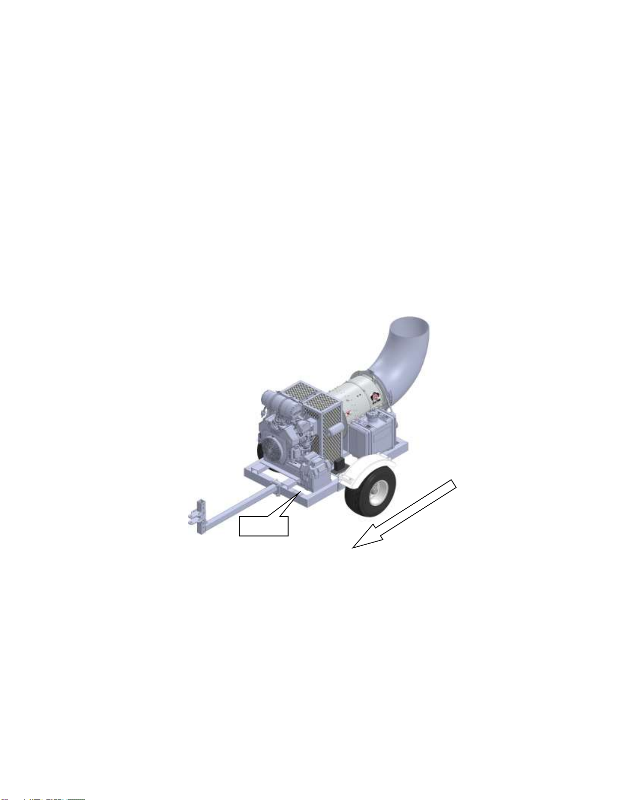
Buffalo Turbine Debris Blowers are designed to quickly and efficiently, blow away leaves, cuttings and other debris. The material is
conveyed on a stream of high volume and velocity of air to remove it from the area of concern. When the material is removed, it gives a
neat, professional look to the working area.
Many of the features incorporated into the machine are the result of suggestions made by customers like you. Read the manual carefully to
learn to operate the machine safely and how to set it to provide maximum efficiency. The manual will take you step-by-step through your
working day. By following the operating instructions in conjunction with a good maintenance program, your Blower will provide many
years of trouble-free service.
Potential Mechanical Hazards while operating your machine:
Never operate the debris blower around others to prevent the possibility of being run over by equipment.
Never ride on your debris blower to prevent the possibility of being thrown off the machine or hurt severely.
Potential Crushing Hazards while operating your machine:
Between Trailer Tongue and mounting hitch on towing vehicle
Between each nozzle
4.2 BREAK-IN
Although there are no operational restrictions on the Blower when it is used for the first time, it is recommended that the
following mechanical items be checked:
A. Operating for first ½ hour
1. Re-torque all wheel bolts, axle nuts and trailer mounting bolts and nuts.
2. Re-torque all other fasteners and hardware.
3. Check set screw (nozzle pulley) to ensure it tightened.
B. Operating for first 5 hours
1. Re-torque all hardware and fasteners.
2. Check set screw (nozzle pulley) to ensure it tightened.
3. Go to the normal servicing and maintenance schedule as defined in the Maintenance Section of the manual.
4.3 PRE-OPERATION CHECKS
Efficient and safe operation of the Buffalo Turbine Blower requires that each operator reads and understands the operating procedures and
all related safety precautions outlined in this section. A pre-operation checklist is provided for the operator. It is important for both personal
safety and maintaining the good mechanical condition of the machine that this checklist is followed.
BATTERY MUST BE CONNECTED BEFORE OPERATION (DISCONNECTED FOR SHIPPING).
Before Operating the Blower and each time thereafter, the following areas should be checked off.
1. For fuel, oil, and operating information of the Kohler Engine, refer to the Manufacturers specs included with this manual.
2. The Model KB turf trailer is not designed for highway towing. For highway use or speeds above 15mph (24kph) an optional DOT
approved trailer must be used.
3. Insure the Blower unit is attached to a proper receiver mounted on the towing vehicle. A pin hitch receptacle is standard with the
model KB. Attach the KB trailer using the proper size hitch pin with a locking presto pin.
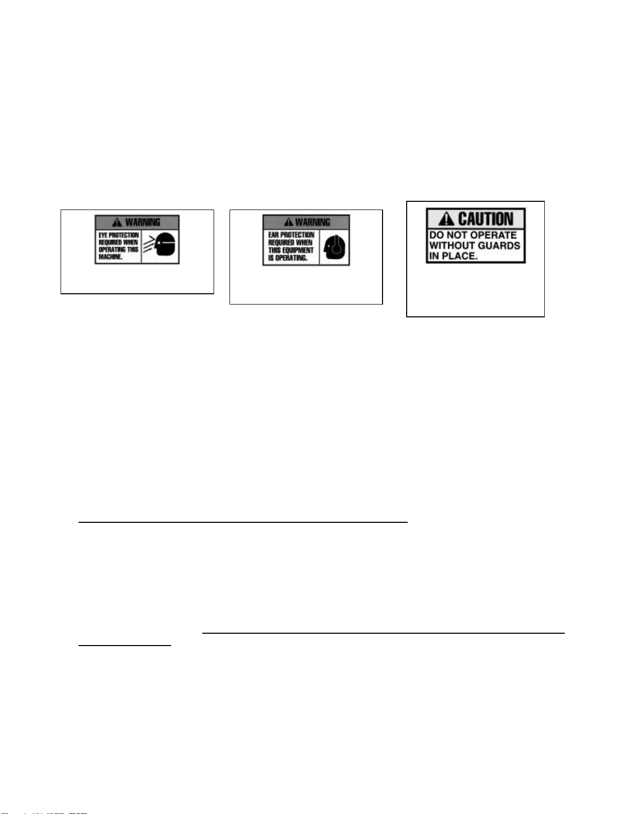
4. Make sure all guards and shields are in place, secured and functioning as designed.
5. Check that all clamp bands are secure.
6. Check the belts and pulleys for proper tension and alignment.
Remote Nozzle and Throttle Control
(REFERENCE PAGES 21-28 FOR WIRELESS REMOTE INSTRUCTIONS)
The throttle control adjusts the engine RPM from an idle to maximum RPM and the nozzle control adjusts the rotation of the nozzle
assembly (360 in either direction).
CAUTION ! DO NOT ALLOW LEAVES OR DEBRIS TO ACCUMULATE ON OR NEAR THE
ENGINE OR EXHAUST SYSTEM OF THE MODEL KB BLOWER, TRACTOR ENGINE OR ANY
INTERNAL COMBUSTION ENGINE.
WARNING:
This Product can expose you to chemicals including carbon
monoxide and benzene, which are known to the State of
California to cause cancer and birth defects or
other reproductive harm.
For more information go to www.P65Warnings.ca.gov.

9
4.4 MODEL BT-CKB5EFI Assembly Instructions
1. Fill engine oil to proper level. (overseas shipments)
2. Fill each cell to proper level (Dry Cell Battery) with battery-grade sulfuric acid of 1.265 specific gravity.
Battery and acid must be at a temperature of 60F to 100F (16C to 38C) at the time of filling (overseas
shipments).
3. Attach 2 axle weldments (part# 1713) with 2 bolts each (part# 1137). Do not tighten. (REF#1)
4. Attach axle (part # 1832) to axle mounts using 2 bolts (part # 1137). Do not tighten. (REF#2)
5. Tighten 4 axle mount bolts then tighten the 2 bolts holding the axle. Use nyloc nuts (part# 1180).
6. Attach the tongue using the 2 U-bolts (part # 1707) and 4 nyloc nuts (part # 1180), center on the frame
then tighten evenly. Equal pressure must be applied on each hex. Note: The tongue is adjustable and will
allow for multiple different heights. Determine the desired height before attaching the tongue. (REF#3)
7. Attach both fenders (part # 1150) using (4) 3/8-16 x 1” carriage bolts (part # 1154), 3/8 lock washer (4)
3/8-16 hex nuts (1155) (REF#4)
8. Recheck all mounting bolts to assure that they are tight.
9. Bolt on tires. (REF#2)
10. Reattach positive battery cable (RED) and ground cable (Black) to proper terminals.
USE PRESTO PIN TO KEEP HITCH PIN IN PLACE WHILE OPERATING
REF# 1
REF# 2
REF# 4
REF# 3

10
4.5 FIELD OPERATION
1. Do not direct debris blower towards people, pets, autos, windows, etc.
2. Starting blower unit: Always start engine at a lower engine speed with nozzle pointed down or away.
3. The air stream direction is changed (in either direction) by pressing the nozzle buttons on the transmitter. The nozzle will stop
turning by releasing the transmitter button. ALWAYS CHECK THE GROUND CLEARANCE WHEN OPERATING THE NOZZLE
IN THE DOWN VERTICAL POSITION.
4. Stopping blower unit: Shut engine off above ½ throttle by turning key switch to off position to avoid engine backfire.
5. Allow the blower fan speed to come to a complete stop before disconnecting from tow vehicle.
4.6 Operating RPM (All Models)
The manufacturer’s engine section normally recommends the unit be run at a RPM that will insure efficient operation. The
Blower can operate at a slower RPM if it can effectively move the debris. Increase engine RPM as needed.
Moving light material, such as dry leaves, requires much less wind than wet or heavier material.
Always try to blow with the wind. The Blower can be used for a wide variety of applications to move leaves, grass clippings,
aeration plugs and debris. Drying wet areas has been another use with these powerful Debris Blowers.
4.7 Storage
At the end of the working season or before storing the blower unit, prepare the machine by following this procedure:
1. Select a storage area that is dry, level and free of debris.
2. Thoroughly wash the machine with a water hose to remove all debris and residue.
3. Run the machine at low RPM to dry the Blower Components.
4. Touch up all paint chips and scratches to prevent rusting.
5. Inspect for worn or failed components. Order the replacement parts and repair the blower unit when time allows. This will
eliminate unnecessary down time at the start of next season.
6. Store in an enclosed building. If space is not available, cover with a waterproof tarpaulin and tie it down securely.
7. Store the machine away from areas of human activity.
8. Do not allow children to play around the stored unit.
5.0 TROUBLE SHOOTING
The Buffalo Turbine Debris Blower uses a high volume and velocity of air to move material from one place to another. The
system is simple and reliable requiring minimal maintenance.
If you encounter a problem that is difficult to solve, even after reading through this trouble shooting section, please call your
local dealer or distributor. Before calling, please have this Operator’s Manual and the serial number from your Blower
ready.
In the following section, we have listed causes and solutions to the problems that you may have encountered.
TURN OFF ENGINE, REMOVE KEY, AND DISCONNECT BATTERY BEFORE SERVICING BLOWER UNITS.
INSTALL GUARDS BEFORE OPERATING.
PROBLEM
CAUSE
SOLUTION
No air flow
Buildup of debris inside turbine
Broken coupling (KB Series)
Remove nozzle and clean debris from inside turbine
Replace coupling
No air flow
Blower fan not turning
See solutions above
Reduced or no air flow
Blower fan turns
Air intake or exhaust restricted
Shut off engine
Blower or tractor –remove restrictions
Debris cannot be allowed to build up between the
blower fan and stationary vanes
Machine vibrates or
Unusual sounds
Bearing or coupling failure
Out-of-balance
Replace bearings or coupling
Have your dealer check blower for damaged blades.
Wash and clean blower fan blades
Wireless system
See diagnostic tests on pages 21-28

11
6.0 Machine Specifications
Model CKB5EFI Series
Length:
Frame Size 28” wide X 48” Long
102” With nozzle
82” Without nozzle
69” With nozzle installed but Without trailer arm
48” Without nozzle and trailer arm installed
Width:
48” With axle and tires
Height:
38.5” With axle and tires
Weight:
470 lbs
Electrical System:
12 Volt battery / 300 CCA
Fuel Capacity:
6 gallon Unleaded Fuel only
Input Power:
ECH749 Kohler Engine (EFI does not have a choke)
Input RPM:
Up to 3900 RPM (more fuel economy when ran below 3600 RPM)
Outlet Size:
Approximately 12”

12
7.0 MAINTENANCE SECTION
7.1 Maintenance Safety
1. Set Blower on a level surface, stop engine, set park brake, remove ignition key and wait for all moving parts to stop
before dismounting to service, adjust or repair.
2. Reinstall and secure all guards removed for servicing before starting to use machine again. *We recommend wearing
gloves when removing or installing the guard to avoid getting cut*
3. Securely support machine with blocks or safety stands when changing tires or working beneath it.
7.2 Fluids
Change oil per Manufacturer’s specification (see Engine owner’s manual section).
A Teflon spray type lubricant on the nozzle base and slides provides for freer rotation.
7.3 SERVICE CHECKLIST
See Lubrication and Maintenance sections for details of service. Copy this page to continue record.
TURN OFF ENGINE, REMOVE KEY & DISCONNECT BATTERY BEFORE SERVICING BLOWER UNIT
CODE: LUBRICATE-(L) / CHECK-(*) / CHANGE-(C) / REPLACE-(B) / CLEAN-(CL)
SCHEDULED MAINTENANCE HOURS ________________________
SERVICED BY ____________________
MAINTENANCE
8 hrs or daily
(*) Remove all debris that has settled between the blower wheel fan and the stationary vanes.
Helps maintain peak performance.
(*) Check engine oil and fill to proper level –Do not overfill
(*) Check air filter and precleaner
(CL) Clean debris from air intake and other cooling areas on the engine
(*) Check tire pressure (Max. 50 PSI)
(*) Check Clamp Band Bolt for tightness
40 hours or weekly
(*) Check condition of coupling (center section # 1256) connecting bolts and nuts during each oil
change or when experiencing vibration or unusual noises. (See page 16)
(*) Inspect battery terminals for any corrosion, broken wires, or loose connections.
(*) Remove Battery and clean debris from inside of battery box
(L) Nozzle base slides (Teflon or Silicone spray)
(*) Check set screw (nozzle pulley) to ensure it is tightened
(*) Wash and Clean any dirt or grime build up that has accumulated on blower wheel
fan blades. Helps to minimize vibration balance and maintain peak performance.
200hrs or annually
(CL) Machine
DO NOT OPERATE BLOWER UNIT WITHOUT GUARDS SECURELY ATTACHED

13
INSTALLATION INSTRUCTIONS & PARTS FOR THE MOREFLEX COUPLING
ALIGNMENT OFTURBINE SHAFT WITH SHAFT OF ENGINE IS CRITICAL
1. Install keys in both shafts.
2. Slide coupling flanges on both shafts (engine and turbine shafts)
3. Place Moreflex coupling CENTER SECTION between coupling flanges and secure with 4 bolts and
TOPLOC nuts. The bolt heads are positioned against the coupling in alternating directions. Tighten all
4 bolts. DO NOT TIGHTEN SET SCREWS AT THIS TIME.
4. Check key for proper position under the set screw hole on both shafts.
5. Place several drops of Loctite 271 into these two holes only. Set screws and tapped screw holes must
be free of dirt and oil for Loctite to work properly.
6. Install the set screws over the keys and tighten firmly.
7. Using a drill point, dimple each shaft through the other 2 set screw holes. Clean drill chips, oil and dirt
before applying Loctite.
8. Place several drops of Loctite 271 in these 2 holes.
9. Install and tighten set screws in these 2 holes.
10. Check and retighten the 4 bolts that hold the coupling center section in place.
11. Visually inspect the unit and replace the guard. DO NOT OPERATE WITHOUT THE GUARDS IN
PLACE.
PART # 1746 –COUPLING COMPLETE, KOHLER ENGINE
Includes PN 1110(1pc), 1111(1pc), 1112(4pc), 1113(4pc), 1114(1pc), 1115(1pc), 1256(1pc), 2869(4pc)
Coupling flange, 1 7/16” bore
Engine - #1115
Coupling flange, 1 ¼
Turbine - # 1114
7/16 –20 TopLoc Nut
(4) required - #1112
7/16-20 x 2 ½ HHCS
Zinc –(4) required - #1113
Center Section
#1256
Key –Engine
3/8 x 2 - #1111
Key –Turbine
¼ x 1 ¾ - #1110
7/16-20 x 3/8" Socket Set Screw
# 2869
Part # 1256 (center section) is a “WEAR” item that should be visually checked each time the engine oil is changed. This
coupling is equipped with special lock nuts. Occasionally check that all 4 nuts are securely fastened. LOOK FOR
CRACKS IN THE RUBBER COMPOSITION THAT SURROUNDS THE 4 BUSHINGS. Replace the center section
when the rubber composition begins to show ANY signs of cracking OR an increase in vibration OR unusual
sounds. When in doubt, call our Service Department.

14
MOUNTING BLOWER ASSEMBLY ONTO FRAME
AND ALIGNMENT RECOMMENDATIONS
1. Install blower assembly onto frame and tighten all of the bolts.
2. Remove all burrs and oil from the shafts and keyways (engine and blower shafts).
3. Using the supplied gauge, align the shafts parallel to each other (very important).
4. Check in four places around the shafts at 90to each other.
5. When properly aligned, gauge should have little to no gap between itself and the shafts at
any point along the gauge.
6. To adjust, move the engine. The 2 mounting brackets have tapped holes in each corner to
help support and adjust the position of the engine. The 4 roll pins may need to be
repositioned after alignment is completed and bolts are tightened.
7. Tighten all engine bolts and recheck alignment. Drill and install 4 roll pins in new position.
ACCEPTABLE
GAUGE
CRANKSHAFT
BLOWER SHAFT
NOT ACCEPTABLE
GAUGE
BLOWER SHAFT
CRANKSHAFT
SECURELY ATTACH GUARDS BEFORE OPERATING BLOWER UNITS

15

16

17

18

19
Table of contents
Other BUFFALO TURBINE Construction Equipment manuals
Popular Construction Equipment manuals by other brands

New Leader
New Leader Hi-Way XT3 TYPE III Operator's manual

Craftsman
Craftsman 919.161020 manual

Harbor Freight Tools
Harbor Freight Tools Central Hydraulics 38024 Assembly and operating instructions

Fayat Group
Fayat Group DYNAPAC DRP25D Original operating instructions

Parkside
Parkside BMR 1400 Operation and safety notes

MW BUILD
MW BUILD MD300 manual