Bug-O Systems K-BUG 6050 User manual

INSTRUCTIONS
AND
PARTS MANUAL
A DIVISION OF WELD TOOLING CORPORATION
280 TECHNOLOGY DRIVE CANONSBURG, PENNSYLVANIA 15317-9564 USA
PHONE: 412-331-1776 http://www.bugo.com FAX: 412- 331- 0383
STAND ALONE
LINEAR WEAVER
K-BUG 6050
Please record your equipment identication information below for future reference. This information can be found
on your machine nameplate.
Model Number
Serial Number
Date of Purchase
Whenever you request replacement parts or information on this equipment, always supply the information you
have recorded above.
LIT-KBUG-6050-IPM-0916
Bug-O Systems is guided by honesty, integrity and
ethics in service to our customers and in all we do.

2
SAFETY
PROTECT YOURSELF AND OTHERS FROM SERIOUS INJURY OR DEATH.
KEEP CHILDREN AWAY. BE SURE THAT ALL INSTALLATION, OPERATION,
MAINTENANCE AND REPAIR PROCEDURES ARE PERFORMED ONLY BY
QUALIFIED INDIVIDUALS.
EQUIPMENT DAMAGE
POSSIBLE.
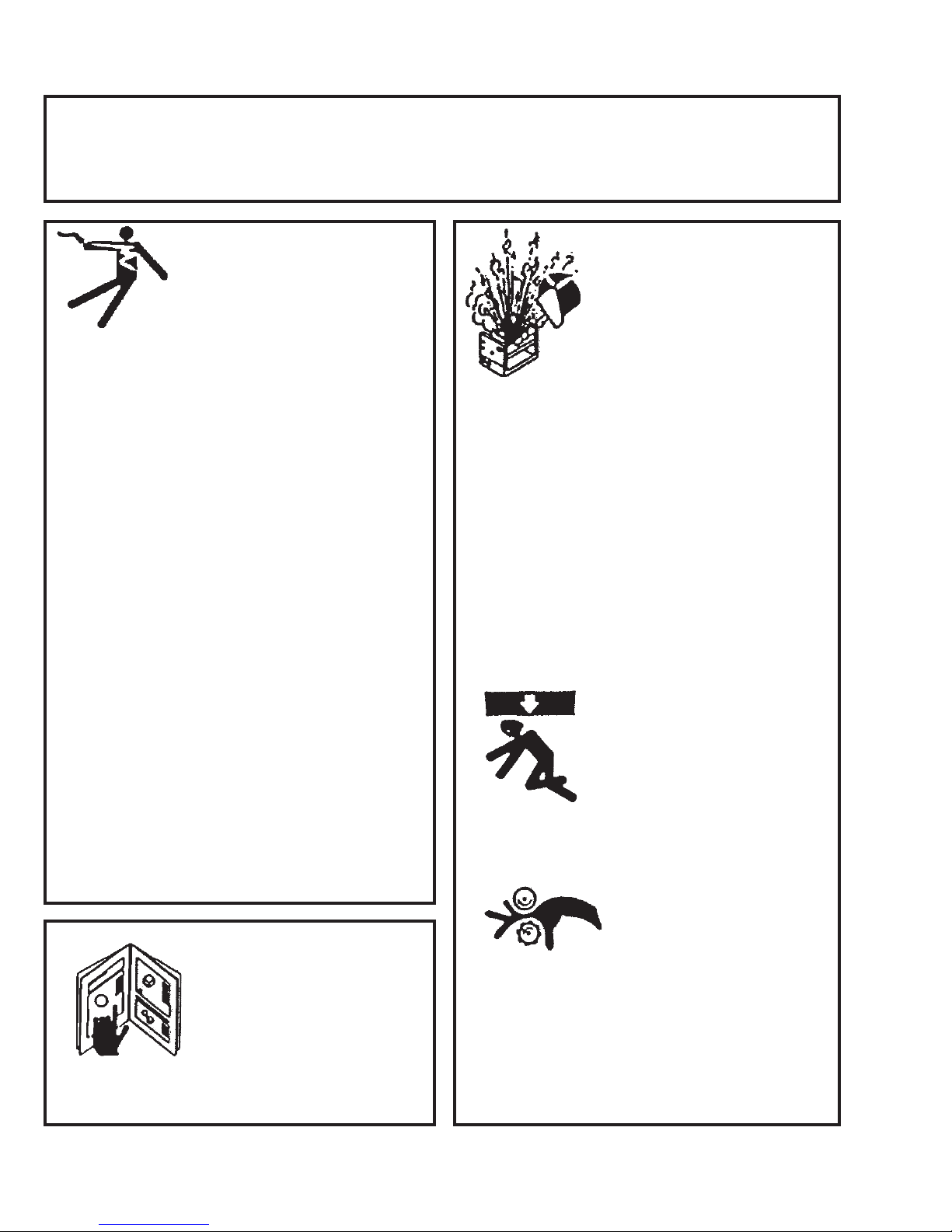
ELECTRIC SHOCK can kill.
1) The equipment is not waterproof. Using
the unit in a wet environment may result
in serious injury. Do not touch equipment
when wet or standing in a wet location.
2) The unused connectors have power on
them. Always keep the unused connec-
tors covered with the supplied protective
panels. Operation of the machine without
the protective panels may result in injury.
3) Never open the equipment without rst
unplugging the power cord or serious
injury may result.
4) Verify the customer-supplied power
connections are made in accordance
with all applicable local and national
electrical safety codes. If none exist,
use International Electric Code (IEC)
950.
5) Never remove or bypass the equipment
power cord ground. Verify the equipment
is grounded in accordance with all appli-
cable local and national electrical safety
codes. If none exist, use International
Electric Code (IEC) 950.
READ INSTRUCTIONS.
Read the instruction manual before
installing and using the equipment.
1) Do not plug in the power cord without rst
verifying the equipment is OFF and the
cord input voltage is the same as required
by the machine or serious damage may
result.
2) Always verity both the pinion and wheels
are fully engaged before applying power
or equipment damage may occur.
3) Do not leave the equipment unattended.
4) Remove from the work site and store in
a safe location when not in use.
1) Never try to stop the pinion from moving
except by removing power or by using the
STOP control.
2) Do not remove any protective panels,
covers or guards and operate equipment.
MOVING PARTS can
cause serious injury.
FALLING EQUIPMENT
can cause serious
personal injury and
equipment damage.
Faulty or careless user installation is
possible. As a result, never stand or walk
underneath equipment.

3
PRECAUTIONS:
1) Some plasma or welding cables are strong sources of high frequency interference.
NEVER lay a plasma or welding cable across the controls of the machine.
2) Always physically separate the plasma or welding cable leads from the machine
cables. For example, the plasma or welding cable leads should NEVER be bundled
with a pendant cable or the machine power cord. Maximize the separation between
any machine cables and the plasma or welding cables.
3) Strictly follow the grounding procedures specied for the plasma or welding unit.
NOTE: Some plasma and welding units produce exceptionally large amounts of high
frequency noise. They may require a grounding rod be driven into the earth within six
feet (2 meters) of the plasma or welding unit to become compatible with an automatic
cutting or welding process.
4) If the high frequency is produced using a spark gap, adjust the points so the gap is as
small as possible. The larger the gap, the higher the voltage and the higher the inter-
ference.
5) Some plasma or welding units will inject high frequency interference into the AC
power line. Use separate power line branches whenever possible to power the
plasma or welding source and the machine. Do not plug them into the same outlet
box.
6) High frequency noise may enter the machine through the plasma or welding supply
remote contactor leads. Some plasma and welding sources can produce noise spikes
of up to several thousand volts. These sources are not compatible with automated
cutting and welding equipment. It is recommended that the remote contactor leads on
these plasma or welding sources not be connected to the machine. An alternate
solution is to purchase a separate remote contactor isolation box.
HIGH FREQUENCY WARNINGS
WARNING: HIGH FREQUENCY CAN EFFECT MACHINE
OPERATION AND THEREFORE, WELD QUALITY.
SPECIAL PRECAUTIONS ARE REQUIRED WHEN USING PLASMA,
TIG OR ANY WELDING PROCESS THAT USES HIGH FREQUENCY
TO STRIKE AN ARC.
Read the precautions below before installing and using the equipment.

4
TABLE OF CONTENTS
STAND ALONE
LINEAR WEAVER
K-BUG 6050
INSTRUCTIONS AND PARTS MANUAL
PAGE
5 ....... Introduction
5 ....... Features
5 ....... Technical Data
5 ....... Dimensions
6 ....... Setup
7 ....... User Interface - Remote Control Pendant
8 ....... Parameter Settings
8 ....... Installation and Operation
9 ....... Maintenance
9 ....... Troubleshooting
10 ...... Troubleshooting, Cont’d.
11 ...... K-BUG 6050 Stand Alone Linear Weaver / Exploded View / Parts List
12 ...... KBUG-6085 Control Pendant / Exploded View / Parts List
13 ...... KBUG-6083 w/ BUG-5188 Optional Torch Holder / Parts List
14 ...... K-BUG 6050 Stand Alone Weaver / Wiring Diagram
15 ...... SBG-450-_-___-__ Gun & Cable Assembly / Exploded View / Parts List
16 ...... Warranty

5
INTRODUCTION
The K-BUG Stand Alone Linear Weaver is a compact unit designed for use with a torch support and
positioner xture or retrot to a carriage. Ideal for llet or butt joints with at or curved proles. Motion
parameters, including weave speed, weave width, and dwell times are digitally controlled by the remote
pendant control. The pendant also offers center steering and interfaces with the welding power source to
control the weld contact.
FEATURES
• Remote Pendant Control (wired 8 ft.)
• Digital displays for weld speed, dwell times, weave width, and weave speed
• Independent left, right dwell times
• All weaving starts and ends in center position
TECHNICAL DATA
Power Input
K-BUG 6050 120 VAC / 50-60 Hz / 1 Ph
K-BUG 6052 240 VAC / 50-60 Hz / 1 Ph
Weight 14 lbs. (6.3 kg)
Drive Motor 24 VDC, 12 W, 5000 RPM
Torch Angle Adjustable
Running Angle 90° +/- 3°
Weave Speed 0 - 100 in/min (2540 mm/min)
Weave Width 0 - 2 in (51 mm)
Dwell Time 0 - 9.9 sec.
DIMENSIONS
Min 4.80" (122 mm)
Max 6.13" (156 mm)
12.25"
(312 mm)
9.125"
(232 mm)
5.30"
(135 mm)
5.78"
(147 mm)
7.40"
(188 mm)

6
SETUP
Cables and Connections
K-BUG 6050 is supplied with two cable assemblies -- a power cable and a weaver control cable. It is also
supplied with a cable connector and a spare 3-pin connector with which the customer is to fabricate a
weld contact interface cable with the welding power source or wire feeder.
• The power cable connects at the 3-pin panel connector
• The weaver control cable connects at the 5-pin panel connector
• The weld contact cable connects at the 2-pin panel connector on the side of the pendant control
• Spare 3-pin connector for power cable
Mounting to a Torch Support
The K-BUG 6050 can be mounted onto a torch support to be used with a positioner. In the gure below,
it is shown mounted on a BUG-O FTS-1020 Torch Support. To do this, remove the Swivel Connector
(CON-1020) and Torch Holder (BUG-2708) from the torch support.
Mounting to a Carriage
The K-BUG 6050 can also be retrotted to a carriage. Additional parts, KBUG-5089 and KBUG-5088, to
provide X-Y racking are required to achieve this.
Mounting to a Fixture
The K-BUG 6050 can be permanently mounted to any customer designed xture or work cell.

7
USER INTERFACE - REMOTE CONTROL PENDANT
The Stand Alone Linear Weaver includes a wired pendant that is used to control the weave parameters.
The Control Pendant includes four digital displays. In addition to displaying real-time values during
welding, the displays are used when presetting parameters (as described on page 8).
DISPLAY INITIAL VALUES
Display Description Range Value Unit
A Left Dwell 0.0 - 9.9 3 sec
BRight Dwell 0.0 - 9.9 3 sec
C Weaving Width 0 - 99 30 %
DWeaving Speed 0 - 99 30 %
Note: The values shown above represent factory settings only. After rst use, the machine will
store and recall last known values as input by the operator.
Left Dwell Display
Start (Black)
Weld Contactor
Auto / Off Switch
Stop (Red)
Center Steering
Weave Speed
Weave Width
Right Dwell
Left Dwell
Weave Speed Display
Weave Width Display
Right Dwell Display
Power Connection
Weld Contact
Connection
Weaver Connection
Fuse Holder

8
PARAMETER SETTINGS
Advanced parameters, like Puddle Build-up and Crater Fill are maintained in a hidden menu. The user
must access this Parameters Menu to view and change these settings.
1. While holding down the Start button, plug the machine into an A/C power source of appropriate
voltage, then release the start button.
2. The active parameter (i.e. “n.0”) will be displayed in the Left Dwell display. The current setting for
the active parameter ( i.e. “1.0”) will be displayed in the Right Dwell Speed display.
3. To adjust the parameter setting, turn the Left Dwell knob. Turning clockwise will increase the value;
counterclockwise will decrease the value.
4. Press and release the Start button to scroll through the parameters.
5. When nished setting (all) values, press the Stop button and unplug the machine.
Display Description Range Default Unit
n.0 Puddle Build-up 0.0 - 9.9 1 sec
n.1 Crater Fill 0.0 - 9.9 1 sec
n.2 Weaving center 10 - 99 99 % (of Max speed)
n.3 Weaving Angle (Width) 0 - 90 15
n.4 Number of Min. 6 - 60 6 Pulse
n.5 Weaving Reduction Gear Ratio 20 - 200 1000 x10
n.6 Demonstration Mode On / Off Off
INSTALLATION AND OPERATION
1. Welding Preparation - Secure the necessary welding supplies
• Welding Power Source and Wire Feeder
• Shielding Gas, with pressure and ow regulators and appropriate ttings
• Torch for gas shielded automated welding
• Basic Weld Prep Tools
2. Welding Process
• Connect the control pendant to an A/C power source of appropriate voltage.
• Mount weaver to torch support or carriage.
• Insert torch and position torch for desired lead/lag angle to match the weld joint and so weld
torch is at desired weld starting point.
• Set desired weave parameters - Weave Width, Weave Speed and Dwell times.
• Verify adequate Shielding Gas Supply, if required.
• Start Welding - Switch Weld Contact switch to AUTO and press Start button.
• Press Stop button when welding is complete. Turn Weld Contact switch to OFF.
• Conrm Welding End.

9
MAINTENANCE
The weaver unit should be periodically checked and cleaned to maximize service life.
Before use:
Check all screws in the torch clamp. Tighten as needed. Loose fasteners may cause inconsistent
weld quality.
During use:
Monitor motor and welding torch for abnormal noise or overheating.
After each use:
1. Clean control panel to remove dust and other debris.
2. Inspect slide adjustment and torch for weld spatter or other debris. Clean as needed.
3. Inspect power cable and torch cable for cracked, cut or damaged insulation. Replace as needed.
4. Inspect connectors for damaged pins or loose connections. Replace as needed.
TROUBLESHOOTING
Symptom Cause Repair
Control Pendant
Display is not LIT
Disconnected Power Cable Verify power cable is properly
connected to machine.
Faulty Power Cable Replace cable.
Control Pendant Fuse Tripped or
Disconnected
Replace fuse. If problem persists,
contact service rep.
No Arc when Start
button is pressed
Weld Contact switch set to OFF Turn Weld Contact switch to AUTO.
Loose contact of Welding Leads Check ground connections. Verify good
contact on clean, unpainted surface.
Bad or incorrectly wired Weld Contact
switch
Check Wiring. Replace switch, if
needed.
Weld Contact Cable is bad or
improperly connected
Verify cable is correctly connected.
Replace cable if bad.
Weld Power Source turned OFF Turn ON Weld Power Source
Torch targets wrong
position
Loose fastener on Torch Clamp Check and tighten screws, replace if
needed.
Arc continues after
Stop button is
pressed
Crater Fill timer has not timed out. Check timer settings and adjust if
needed.
Faulty or incorrectly wired Stop button Check Wiring. Repair as needed.

10
TROUBLESHOOTING, CONT’D.
K-BUG ERROR LIST
NO. SYMPTOM CAUSE SOLUTION
E-05 Weave Stop Auto-Stop Weaving Motor Push and release Stop Button
may be overloaded / shorted
IF UNRESOLVED:
1. Check for loose wiring connec-
tion at weave motor (see below).
2. Replace motor or motor reducer
3. Replace main PCB

11
K-BUG 6050 STAND ALONE LINEAR WEAVER / EXPLODED VIEW /
PARTS LIST
ITEM QTY PART NO. DESCRIPTION
1 1 KBUG-6092 Linear Weaver Assembly
2 1 KBUG-6055 Linear Weaver Mount
3 1 KBUG-4090 Torch Clamp Assembly
4 1 KBUG-6085 Control Box w/ Weld Contact
* 2 KBUG-1131 Fuse
* 1 KBUG-1173 Weld Contact Connector
* 1 KBUG-1174 Power Connector
* 1 KBUG-2274-15 120V Power Cord, 15'
* 1 KBUG-2275-8 8' Weaving Cable 5 Pin
* Not Shown
1
3
4
2

12
KBUG-6085 CONTROL PENDANT / EXPLODED VIEW / PARTS LIST
ITEM QTY PART NO. DESCRIPTION
1 1 KBUG-6084 Pendant Housing
2 1 BUG-9487 Cable Connector, 2T, F (Weld Contact)
3 1 BUG-9486 Panel Connector, 2T, M (Weld Contact)
4 1 KBUG-3116 Panel Connector, 5T, M (Weaver)
5 1 KBUG-1132 Panel Connector, 3T, M (Power)
6 1 KBUG-1131 Fuse (Holder)
7 1 KBUG-6087 Magnet Plate
8 1 KBUG-6088 Wearing PCB
9 2 KBUG-3112 Push Button
10 1 KBUG-3114 Toggle Switch
11 1 KBUG-6086 Face Plate (or Top Panel)
12 1 KBUG-1122 Toggle Switch Cover
13 1 KBUG-1128 Push Button Cover, Black
14 1 KBUG-1127 Push Button Cover, Orange
15 5 KBUG-1129 Volume Knob
16 4 FAS-0504 Screw, Soc Hd Cap, 4-40, 3/8
17 4 FAS-1305 Hex Nut, 4-40
18 1 KBUG-6089 Power PCB
19 1 KBUG-6097 Magnet
20 1 KBUG-6098 Magnet Case
1
2
3419
20
5
7
8
11
9
13
14
12
6
15
17
16
10
18

13
ITEM QTY PART NO. DESCRIPTION
1 1 KBUG-6082 Plasma Torch Holder
2 2 FAS-0559 Soc HD Cap 1/4-20 x 1
3 2 WAS-0240 1/4 SAE Flat
4 1 BUG-5188 Torch Holder Assy.
1
2
3
KBUG-6083 W/ BUG-5188 OPTIONAL TORCH HOLDER / PARTS LIST
4

14
K-BUG 6050 STAND ALONE WEAVER / WIRING DIAGRAM
KBUG-6089
KBUG-6088
KBUG-6088

15
PARTS LIST WIRE SIZE
ITEM QTY PART NO. DESCRIPTION
.035
(.9 mm)
.040
(1.0)
.045
(1.2)
.052
(1.4)
1/16
(1.6)
5/64
(2.0)
1 1 BUG-3159-35 16S-35 (.9 mm) Contact Tip X
1 1 BUG-3159-45 16S-45 (1.2 mm) Contact Tip X
1 1 BUG-3159-52 16S-52 (1.4 mm) Contact Tip X
1 1 BUG-3159-116 16S-116 (1.6 mm) Contact Tip X
1 1 BUG-3159-564 16S-564 (2.0 mm) Contact Tip X
1 1 PWS-4436-1.0 16S-40 (1.0 mm) Contact Tip X
2 1 PWS-4447 27S62 H.D. Nozzle ⅝" X X X X X X
3 1 PWS-4449 PX57HD Gas Diffuser X X X X X X
4 1 CWO-8017 Case w/ Binder Screws (Front) X X X X X X
5 1 PWS-4411 Case w/ Binder Screws (Back) X X X X X X
6 1 STW-3044 450 Amp Cable X X X X X X
7 1 R174-T Connector, Small Lincoln
7 1 R174-L Connector, ¾" Lincoln
7 1 R174-M Connector, Miller
7 1 R174-X Connector, Euro
8 1 CWO-8009 44-3545-15 Cable Liner X X X
8 1 CWO-8011 44-116-15 Cable Liner X X
8 1 CWO-8012 44-564-15 Cable Liner X
** 1 SBG-1004 Gas Hose Assembly X X X X X X
** 2 SBG-1005 Gas Hose Clamps X X X X X X
** Not shown. Required only with standard Lincoln guns (SBG-450-L).
SBG-450-_-___-__ GUN & CABLE ASSEMBLY / EXPLODED VIEW / PARTS LIST
Whip Length: 15 (15 ft / 4.6 m) or 25 (25 ft / 7.6 m)
Wire Size: 035, 040, 045, 052, 116, 564
Connector Type: E (Euro), L (Lincoln ¾"), M (Miller), T (Lincoln, small)
4
4
5
5
7
3
1
2
6
8
6

16
WARRANTY
FOR A PERIOD OF TWELVE (12) MONTHS FROM DELIVERY, BUG-O SYSTEMS WARRANTS TO THE ORIGINAL PURCHASER
(DOES NOT INCLUDE AUTHORIZED DISTRIBUTORS), THAT A NEW MACHINE IS FREE FROM DEFECTS IN MATERIAL
AND WORKMANSHIP AND AGREES TO REPAIR OR REPLACE, AT ITS OPTION, ANY DEFECTIVE PARTS OR MACHINE.
THIS WARRANTY DOES NOT APPLY TO MACHINES, WHICH AFTER OUR INSPECTION, ARE DETERMINED TO HAVE
BEEN DAMAGED DUE TO NEGLECT, ABUSE, OVERLOADING, ACCIDENT OR IMPROPER USAGE. ALL SHIPPING AND
HANDLING CHARGES WILL BE PAID BY CUSTOMER.
BUG-O SYSTEMS MAKES NO WARRANTY OF MERCHANTABILITY AND MAKES NO OTHER WARRANTY, EXPRESSED OR
IMPLIED, BEYOND THE WARRANTY EXPRESSLY SET FORTH ABOVE. BUYER’S REMEDY FOR BREACH OF WARRANTY,
HEREUNDER, SHALL BE LIMITED TO REPAIR OR REPLACEMENT OF NON-CONFORMING PARTS AND MACHINES. UNDER
NO CIRCUMSTANCES SHALL CONSEQUENTIAL DAMAGES BE RECOVERABLE.
HOW TO OBTAIN SERVICE:
IF YOU THINK THIS MACHINE IS NOT OPERATING PROPERLY, RE-READ THE INSTRUCTION MANUAL CAREFULLY,
THEN CALL YOUR AUTHORIZED BUG-O DEALER/DISTRIBUTOR. IF HE CANNOT GIVE YOU THE NECESSARY SERVICE,
WRITE OR PHONE US TO TELL US EXACTLY WHAT DIFFICULTY YOU HAVE EXPERIENCED. BE SURE TO MENTION
THE MODEL AND SERIAL NUMBERS.
LIMITED WARRANTY MODEL ____________________________
SERIAL NO. ________________________
DATE PURCHASED: _________________
Table of contents
Popular Welding Accessories manuals by other brands

BUILDPRO
BUILDPRO T50430 Assembly instructions

Lincoln Electric
Lincoln Electric IM573 Calibration information

Lincoln Electric
Lincoln Electric STATIFLEX 400-MS user manual

Miller Electric
Miller Electric 301239 owner's manual

Lincoln Electric
Lincoln Electric AUTO-DARKENING HELMET IM10001 Operator's manual

Lincoln Electric
Lincoln Electric CAN-M568 user manual