Buggies4One RAMBLA Mk 1 User manual

Page 1
USER MANUAL
RAMBLA Mk 1

Page 2
CONTENTS
RECEIVING & CHECKING YOUR BUGGY……………….3
TECHNICAL INFORMATION..……………………………….5
ASSEMBLY (FIRST TIME)..……………………………………8
OPERATING FUNCTIONS…………………………………….11
LOADING & UNLOADING……………………………………15
DRIVING SAFELY………………………………………………...16
MAINTENANCE…………………………………………………..17
TROUBLE SHOOTING………………………………………….19
YOUR BUGGY DETAILS……………………………………….21
WARRANTY DETAILS…………………………………………..22

Page 3
RECEIVING YOUR GOLF BUGGY
On receiving your Buggy we suggest the Instruction Manual is read through
carefully.
The manual provides instruction on how to drive safely, includes technical
information, maintenance routines and troubleshooting chart.
Please fully check receipt of ALL separate parts. These are as follows:
1. Rear Body Assembly
2. Front Body Assembly
3. Seat
4. Seat Support Pillar
5. Lithium Battery
6. Front Fender
7. Basket
8. Golf Bag Holder
9. Umbrella Holder
10. Rear Stabilizer
11. Charger and Separate Charger Lead
12.User Manual
13.Ignition Key (2 off)

Page 4

Page 5
TECHNICAL INFORMATION
Full dimensions (LxHxW) 1510x1093x743mm
Folded dimensions(seat & fender removed) 1420x640x743mm
Front & Rear Sections separated (minimum) 1050x600x743mm
Total weight of Buggy (including battery) 77kg
Heaviest individual part (Rear Body) 35kg
Maximum carrying capacity 200kg
Motor/gearbox output 1000watt
Battery 24V…..50ah
Battery Weight 7.5kg
Wheel Size 13”x 5” –6” Rim
Max. Forward speed 12.5km/h
Max. Reverse speed 8km/h
Climbing capacity 15° (1 in 4)

Page 6
EXPLODED VIEW

Page 7
PRIMARY COMPONENT LIST
ITEM NO
PART NUMBER
DESCRIPTION
QTY PER
1
BF1-10
MOTOR/GEARBOX ASSEMBLY
1
2
BF1-71
REAR STABLISER ASSEMBLY
1
3
BF1-30
TEE HANDLEBAR ASSEMBLY
1
4
BF1-73
FRONT FENDER
1
5
BF1-50
FRONT FRAME ASSEMBLY
1
6
BF1-72
FOOTBOARD MAT
1
7
BF1-22-02-RED
FRONT OFFSIDE MUDGUARD
1
8
BF1-22-03-RED
REAR OFFSIDE MUDGUARD
1
9
BF1-40
REAR FRAME ASSEMBLY
1
10
BF1-22-04-RED
NEARSIDE FRONT MUDGUARD
1
11
BF1-22-01-RED
NEARSIDE REAR MUDGUARD
1
12
BF1-60
SEAT ASSEMBLY
1
13
BF1-70
GOLF BAG BASE SUPPORT
1
14
BF1-11-L50
50 AH LITHIUM BATTERY
1
15
BF1-20
WHEEL ASSEMBLY
4
16
BF1-30-06
THUMB ACCELERATOR
1
17
BF1-30-18
USB HOLDER
1
18
BF1-60-09
UMBRELLA HOLDER
1
19
BF1-50-07
STEERING TIE ROD
2
20
BF1-13
MOTOR CONTROLLER
1
21
BF1-30-07
FRONT BASKET
1
22
BF1-60-07
UPPER GOLF BAG RETAINER
1

Page 8
ASSEMBLY (FIRST TIME)
Your Golf buggy has been assembled, and fully tested prior to despatch. It
has arrived part dismantled for boxing and shipment. Assembly is straight
forward and can be accomplished with the tools supplied.
Remove all parts from the box.
Line up Rear and Front body sections and push together until they lock. A
spring-loaded pin will hold them together.
Connect the Multi-Pin Jack Plug and Screw on the locking cap.

Page 9
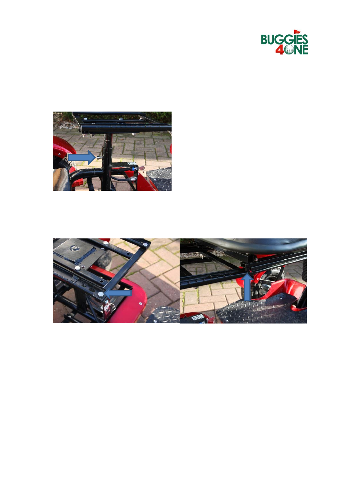
Fit the Seat Support pillar. Locate the bolt into the centre hole and tighten.
Height adjustment up or down can be done later to suit the driver. Make
sure the orientation is correct.
The seat can be assembled from the front by locating the sliders onto the
end of the guide rails. It will slide on and stop. By operating the seat
adjuster, the final position can be chosen.
The seat can be adjusted 2 ways.
1) Forward/Backward –Pull the lever under the right-hand side of the
seat and adjust to desired position.
2) Vertical –3 different height positions adjusted by removing the nut
and bolt on the centre support.

Page 10
Note
The Lithium battery will come approximately 50% charged. It is
recommended prior to the buggy being used that it is fully charged.
Install the battery in the nearside compartment and connect the power
lead. The power lead can only be inserted when located correctly.
Fit the Basket, Golf Bag Holder, Umbrella Holder and Front Fender as
required.
The Rear Stabilising Wheel should be fitted if the buggy will be used on
particularly hilly courses.

Page 11
OPERATING FUNCTIONS
KEY SWITCH
Controls the power supply from the battery to the Buggy. When turned to
the “ON” position the indicator on the handlebar will illuminate. The buggy
is ready to operate.
CHARGING PORT
Located underneath the seat is the charging port for the battery. The
charger can be connected using this port and plugged into a suitable mains
power supply. The buggy should be switched “OFF” whilst charging. The
system is equipped with a lock out to prevent the buggy being used whilst
on charge.
A separate charging port is fitted to the battery and can be used when not
connected to the buggy. It is recommended if this port is used when still
fitted to the Buggy then remove the power lead prior to charging.
Always use the supplied equipment for charging. Lithium batteries use a
different charger to Lead/Acid ones. Attempting to charge the battery any
other way whilst connected to the buggy’s electrical system could cause
permanent damage to the controller unit.
Switch
FUNCTIO
NS
KEY
SWITCH
Controls
the
power
supply
from the
battery
to the
Buggy.
When
turned to
the “ON”
position
the
indicator
on the
handle
bar will
illuminat
e. The
buggy is
ready to
operate.
Charge

Page 12
THUMB ACCELERATOR CONTROL
Controls forward and reverse motion. With the key switch “ON” the 3 LED
indicators light up. These indicate the battery level, with all 3 on the battery
is fully charged.
With the brake lever in the up position gentle pressure on the accelerator
lever will drive the buggy under power. More pressure will increase the
speed. Releasing the accelerator will automatically engage the braking
system.
To change direction i.e., forward, or reverse press the red button on the
thumb control. Care should be taken to ensure the buggy has come to a
stop with the brake on before changing direction.
GO/STOP
Fwd/Rev.

Page 13
BRAKE RELEASE LEVER
When engaged (Lever in the down position) the buggy is in drive mode. To
change to freewheel mode the lever is pushed up. When pushed up the
buggy drive is inoperative.
HANDLEBAR
The handlebar position can be adjusted by loosening the locking nut at the
base of the bar. Ensure it is firmly tightened before driving off.
Drive
Free Wheel

Page 14
USB PORT
The buggy is fitted with a dual USB charging port for connecting directly
into a mobile phone, GPS device or other suitable equipment.
POWER SAVE
In order to save battery life if the key switch is left “ON” the electrical
system after 20 minutes will go to power save. It is then necessary to switch
the key “OFF” and then “ON” to restore power.
JACK PLUG
Electrical power to the front unit is via a multi pin plug located between the
Front and Rear body sections.
Ensure the power is “OFF” before connecting or disconnecting.
When connecting it needs to be correctly orientated and locked together
using the screw cap.
This should always be disconnected prior to the body units being separated
in order to prevent damage to the cabling.

Page 15
LOADING & UNLOADING
With many SUV’s and estate cars it is often possible to load the buggy
without dismantling the 2 main body frames. The use of suitable loading
ramps is recommended. The handlebars can be dropped down, the basket
can be removed if necessary together with the front fender, stabilizer wheel
and golf bag support.
If using motive power stand to the right side when operating. Do not stand
behind the buggy in case it rolls back.
It may be necessary, however, when loading it into a vehicle, to dismantle
the buggy. It can be separated into easily handled parts with the heaviest
item weighing 35kg.
Disconnect the battery by separating the connection plug.
If separating the 2 main units, ensure the jack plug is disconnected first. Pull
the spring-loaded pin, located under the rear section, and slide the
connection bar outwards.

Page 16
DRIVING SAFELY ON THE GOLF COURSE
1. Good practice is to always have the battery fully charged when going
out for a round.
2. Check all component parts are in good working order.
3. Make sure the Buggy is assembled correctly.
4. Make sure the Golf clubs are securely fastened.
5. Assess the conditions of the day and ensure you operate the buggy
safely dependent on those prevailing conditions.
6. Make sure the distance round the course is going to within the
limitations of the Buggy.
7. Don’t climb gradients outside the abilities of the Buggy (Max.Incline
15°). Fit the rear stabiliser on hilly golf courses and be careful driving
parallel to steep inclines to avoid tipping over.
8. Pay consideration to your fellow golfers and maintain a safe distance.
9. When stopping to take a shot, if possible, park on level ground. It
makes it easy to dismount.
10.It is good practice after reversing your buggy to reset to forward
drive. This avoids confusion particularly after returning from a shot.
11.Sharp turning at full speed can be hazardous with the risk of
overturning, particularly on inclines.
12.Avoid erratic use of the speed control. Releasing the button at speed
causes skidding damaging the grass and upsetting the green keeper.
Also avoid pressing the reverse button whilst still moving. This may
force the control box to shut down and you will have to wait until the
unit resets itself (approx. 5minutes).
13.If possible, avoid heavy rain. The buggy is water resistant but not
watertight. Do not drive through deep puddles. More than 15cm will
flood the motor and damage it beyond repair. Driving even through
shallower water at speed can result in a wave forming.

Page 17
MAINTENANCE
The Buggy in general requires minimal maintenance and relies mostly on
good housekeeping to remain in good working condition.
Battery
The lithium battery requires no maintenance. It is supplied pre-charged but
will require a full charge before use.
To charge the battery this can be done in situ on the buggy or using the
separate charging cable supplied.
To charge on the Buggy remove the ignition key and plug the charger into
the charging port situated below the key switch. Plug the charger into a
suitable mains supply. The charger will automatically control the charging
rate and close down when the battery is fully charged. The charger is
equipped with a cooling fan so the noise from the unit is normal.
To charge away from the buggy disconnect the battery and connect the
adaptor cable into the battery.
Only use the charger supplied with the Buggy.
The battery will slowly discharge over a period of time and its good practice
not to let it go too low. If not used for a long time do not leave the battery
on charge since this can reduce the life. Maintain it at 50-80% charge.
Motor/Gearbox
No maintenance required other than keeping it free from mud and other
debris. The carbon brushes will wear after a period of time (12-24 months)
and will need replacing. A set of brushes & caps can be purchased and are
simple to fit.

Page 18
Controller
Located in the box under the seat it requires no maintenance other than
checking cable connections look in good condition and are free from dirt
and debris.
Jack Plug
Located underneath the junction between the front and rear body section it
can collect dirt and should be wiped clean. Apply WD40 occasionally as this
will help to dispel water.
Tyres
Max Tyre Pressure 28psi (1.9bar)
Min. Tyre Pressure 10psi (0.7bar)
Generally, the tyres can be set between 12 –18psi dependent on ground
conditions and individual preferences.
Check tyre pressure and wear on a regular basis.

Page 19
TROUBLESHOOTING
No lights on the controller
REASON
TRY
Key Switch is off
Turn On
Battery is Flat
Recharge Battery
Jack Plug disconnected
Reconnect
Battery Lead Disconnected
Reconnect
Control unit damaged
Contact Retailer
Lights are lit but Buggy fails to drive.
REASON
TRY
Brake lever in down position
Move to up position for drive
Possible loose wire in control box
Check connections
Direction button stuck
Press in & out a few times
Jack plug not engaged correctly
Reinsert
Gearbox failure
Contact retailer
Electric Brake stuck
Contact retailer
Buggy will not freewheel.
REASON
TRY
Brake release lever in down
position
Push up out of drive
Ignition switched on
Turn off Ignition
Debris caught in wheels
Remove and try again
Brake malfunction
Contact retailer

Page 20
Buggy pulls to one side
REASON
TRY
Unequal tyre pressure
Check and reset
Steering rods out of alignment or
damaged
Contact retailer
Damaged gearbox
Contact retailer
Buggy struggles to drive.
REASON
TRY
Low on power
Check Battery condition
Excessive Weight
Reduce weight
Tyre pressure low
Inflate above 10psi min.
Debris caught on wheels
Remove
Excessive heat in motor/gearbox or
controller
Stop and let it cool down
Gradient too steep
Try another route
Lack of traction
Find firmer ground
Damage to bearings or buggy
Stop using and contact retailer
The buggy is working but stops after a short distance.
REASON
TRY
Battery not charged
Check battery condition
Jack plug has disconnected
Reconnect
Brake lever has moved
Move down into drive position
Wiring connection loose
Check connections in black box
Table of contents