A Division of Vcom MM Corp.
South Hackensack, NJ 07606, USA
Tel.:(800)631-0868
If any parts or hardware are missing or damaged, Do Not
Return the unit to your dealer. Call the Buhl helpline at
(800)742-5672 for immediate parts replacement.
Page 2
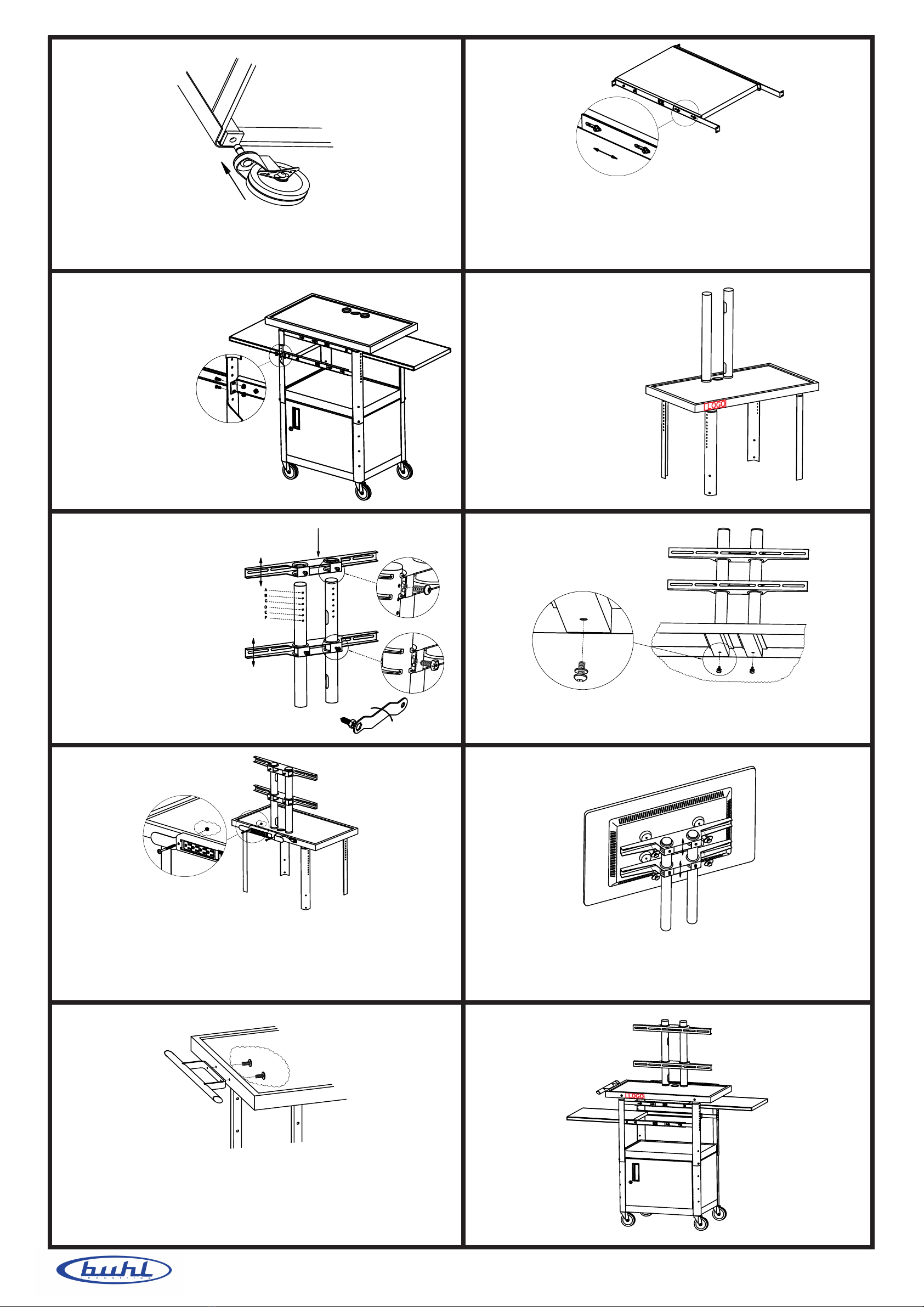
7.
Insert the two
supporting poles
onto the holes
on top shelf.
Wire holes can
face inside or
outside.
B.
Tighten the pull out
shelf onto leg on
both side as shown.
9.
Tighten the two supporting poles onto the top shelf with two
security screws (see screw table F) as shown.
8.
Insert the two horizontal
mounts onto the
supporting poles. Note:
The mount with
adjustable screw(see
screw table H) should
go on the bottom. Screw
(see screw table G) the
top mount to desired
height from A to F.Adjust
the bottom mount height
according to the TV
screw position as shown.
11.
Use the appropriate security screws needed (M4, M5, M6 or M8,
see screw table A,B,C or D) to fasten the flat panel TV onto the
horizontal mounts as shown.
10.
Electrical bracket assembly instruction
A. Push power cord into cord winder bracket.
B. Attach electrical bracket to back side of top shelf with two nuts
and bolts(see screw table E). Tighten nuts and bolts securely.
Wrap power cord around wings of the bracket.
6. pull out shelf assembly instruction
A. Due to limited packaging space, pull-out shelf was shorten.
Adjust the pull-out shelf out to the maximum inside width of
the cart inside as the pull-out shelf will be installed inside of
the legs.
5.
Lay unit on floor . Insert casters with brakes into opposite
corner holes in the bottom of the unit. Insert other casters into
remaining holes of unit.
Top horizontal mount
Bottom horizontal mount
12.
Handle assembly Instruction ( Optional )
A. Unscrew the scews from the handle.
B. Attach the handle to the top shelf (either side) and tighten
handle to the shelf with screws from the inside under the shelf
as shown.


