BULK REEF SUPPLY HEATER CONTROLLER User manual

HEATER
CONTROLLER
Code Function Setting Default
TS1 Temperature
Set Value
-50° to 37.7°C
/ -58° to 99.9°F 25°C / 77°F
DS1 Heating
Differential Value
0.3° to 15°C
/ 0.3° to 15°F 2°C / 2°F
CA Temperature
Calibration
-15° to 15°C
/ -15° to 15°F 0°C / 0°F
CF Display in
°F or °C °C / °F °C
MENU KEY
When TR=0 (default)
SETTINGS
Temperature Control Range Setting (TS1, DS1)
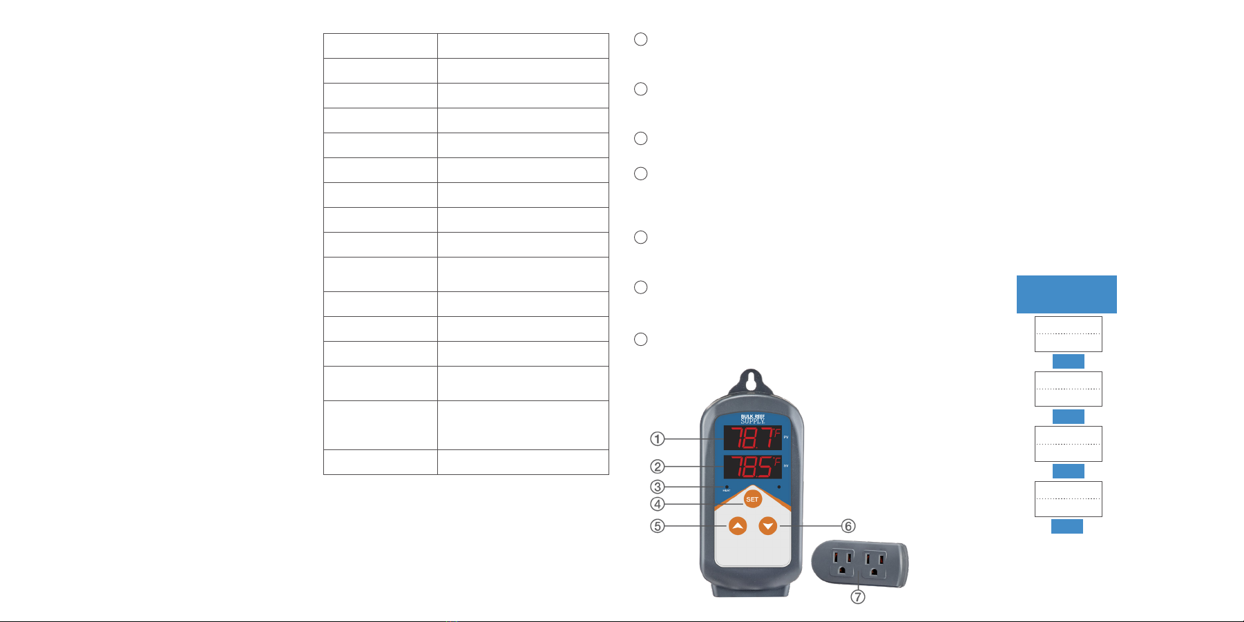
When the controller is working normally, the PV
window displays current measured temperature,
while the SV window displays set temperature.
When PV (measured temperature) ≤ TS1 (set
temperature)-DS1 (temperature differential value),
system will enter heating status, the Heater
Indicator Lamp will turn on, and heating relay
will start working; when PV ≥ TS1, the Heater
Indicator Lamp will turn off, and heating relay
will stop working.
For example, if TS1 = 78.5°F, DS1 = 0.5°F, when
measured temperature is lower than or equal to
78.0°F (TS1-DS1), heater turns on; when the
temperature reaches 78.5°F, heater turns off.
Temperature Calibration (CA)
When there is deviation between measured
temperature and actual temperature, use
temperature calibration function to align the
measured temperature and actual temperature.
The corrected temperature is equal to temperature
before calibration plus corrected value (corrected
value could be positive value, zero, or negative value).
Display in Fahrenheit or Celsius unit (CF)
Temperature can be set to display in Fahrenheit or
Celsius according to preference. Default setting is to
display in Celsius. To display in Fahrenheit, set CF
value to F.
Attention: when CF value is changed, all other
settings will be reset to factory settings.
ERROR DESCRIPTION
Sensor fault alarm
If the controller detects a fault in the temperature
sensor, either due to a short circuit or open loop,
the controller will initiate sensor fault mode, and
cancel all the actions. An alarm will sound, and LED
will display “ER”. Buzzer alarm can be dismissed by
pressing any key. After fault is solved, the system will
return to normal operation.
Over-temperature alarm
If the measured temperature exceeds the set point
(TS) by more than 3°F, the controller will initiate
over-temperature alarm mode, and cancel all actions.
An alarm will sound and LED will display “HL”.
Buzzer alarm can be dismissed by pressing any key.
When the measured temperature returns to within
3°F of the set point, the system will resume normal
operation.
YEAR
WARRANTY
1
Questions?
bulkreefsupply.com
support@bulkreefsupply.com

TS1 Temperature
Set Value 1
Heating
Differential
Temperature
Calibration
Temperature
Unit
25°C / 77°F
DS1
.5°C / .5°F
SET
SET
SET
SET
HOLD SET FOR
3 SECONDS FOR
SET-UP MODE
CA
0°C / 0°F
CF
F
OVERVIEW
The Bulk Reef Supply Heater controller is a pre-wired
heating output temperature controller for use with
a separate heating element. This heater controller
offers some key advantages that ensure long-term
accuracy and reliability.
MAIN FEATURES
• Dual display window; displays measured
temperature (PV)and set temperature (SV)
at the same time
• Fast and easy programming
• Temperature calibration
• Adjustable control precision; down
to 0.3°F heating differential value
• Replaceable probe
• Large power output (Max load: 1,200W (110v))
• Sensor fault alarm
• Supports readings in Fahrenheit or Celsius
• Over-temperature alarm
OPERATING KEYS
PV: Process Value
Displays current temperature
In setting mode: displays menu code
SV: Setting Value
Displays set temperature
In setting mode: displays setting value
Heater Indicator Lamp
When lit, indicates outlets are on
SET
Press SET for 3 seconds to enter menu for
parameter setting. When done, press SET for
3 seconds to quit and save setting changes
Increase
In setting mode: press pto increase or
change setting value
Decrease
In setting mode: press qto decrease or
change setting value
Socket
Both sockets are for heating output and are
synchronized
SPECIFICATIONS
Control Range -50° to 37.7°C / -58° to 99.9°F
Control Precision 0.3° to 15°C / 0.3° to 15°F
Display Resolution 0.1°C / 0.1°F
Accuracy ±1°C / ±1°F
Control Mode On/Off Control, Heating
Input Power 100 to 265VAC, 50Hz/60Hz
Output Max. 10A, 100V to 265VAC
Sensor Type NTC sensor
Sensor Length 6.5’
Relay Contact
Capacity Heating (10A, 100 to 240VAC)
Cable Length Input: 5’ / Output:1’
Body Dimension 5.5x2.7x1.3”
Socket Dimension 3.3x1.7x1”
Ambient
Temperature -30° to 75°C / -22° to 167°F
Storage
-20° to 60°C / -4° to 140°F
Humidity 20 to 85%
(No Condensate )
Warranty 1 Year
1
2
3
4
5
6
7
PROGRAMMING
When the controller is working normally, press SET
for 3 seconds to enter parameter setting mode. PV
window displays the temperature setting code TS1,
while SV window displays according setting value.
Press SET to go to the next menu; press por q
key to set desired parameter value.
When finished, press SET for 3 seconds to save the
settings and return to normal temperature display
mode. While in setting mode, if there is no operation
for 10 seconds, the system will automatically quit
setting mode and return to normal temperature
display mode without saving changes.