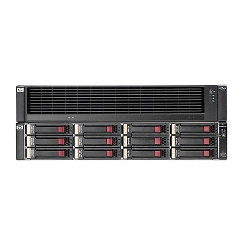
Bull DPS7000/XTA NOVASCALE 7000 CDA 7 5630 User manual

CDA 7 5630
Maintenance Manual
DPS7000/XTA
NOVASCALE 7000
Hardware: CDA
REFERENCE
77 A7 48UU 03


DPS7000/XTA
NOVASCALE 7000
CDA 7 5630
Maintenance Manual
Hardware: CDA
December 1999
BULL CEDOC
357 AVENUE PATTON
B.P.20845
49008 ANGERS CEDEX 01
FRANCE
REFERENCE
77 A7 48UU 03

The following copyright notice protects this book under Copyright laws which prohibit such actions as, but not
limited to, copying, distributing, modifying, and making derivative works.
Copyright Bull SAS 1994, 1999
Printed in France
Suggestions and criticisms concerning the form, content, and presentation of this
book are invited. A form is provided at the end of this book for this purpose.
To order additional copies of this book or other Bull Technical Publications, you
are invited to use the Ordering Form also provided at the end of this book.
Trademarks and Acknowledgements
We acknowledge the right of proprietors of trademarks mentioned in this book.
Intel®and Itanium®are registered trademarks of Intel Corporation.
Windows®and Microsoft®software are registered trademarks of Microsoft Corporation.
UNIX®is a registered trademark in the United States of America and other countries licensed exclusively through
the Open Group.
Linux®is a registered trademark of Linus Torvalds.
The information in this document is subject to change without notice. Bull will not be liable for errors contained
herein, or for incidental or consequential damages in connection with the use of this material.

77 A7 48UU Rev03 iii
Preface
This manual is part of the documentation set for the CDA 7 family of products.
The CDA 7 is a very reliable high performance Integrated Cached Disk Array
(ICDA) designed for online data storage.
This manual describes CDA 7 maintenance and ORU replacement procedures.
This manual is intended for personnel involved in maintaining and repairing the
CDA 7 5330.
Versions of the Product
•For GCOS 7 systems, the CDA 7 5330 subsystem is available with two disk
technologies giving two different disk capacities: 9 GB and 18 GB.
9 GB refers to the formatted disk capacity. This is equivalent to an unformatted
disk capacity of 11.5 GB.
18 GB refers to the formatted disk capacity. This is equivalent to an unformatted
disk capacity of 23 GB.
This manual applies to both the 9 GB and 18 GB disk technologies. However, if
a section of text applies only to just one disk technology (9 GB or 18 GB), then
this is explicitly stated in the text. If no such indication is given, then the text
concerned applies to both the 9 GB and the 18 GB disks.
•CDA 7 5630 is available with 18 GB or 36 GB disk devices.
18 GB refers to the formatted disk capacity. This is equivalent to an unformatted
disk capacity of 23 GB.
36 GB refers to the formatted disk capacity. This is equivalent to an unformatted
disk capacity of 47 GB.
Scope and
Objectives
Intended
Readers

CDA 7 Maintenance Manual
iv 77 A7 48UU Rev03
This manual is structured as follows:
Chapter 1 Introduction, provides a overview of the CDA 7
system.
Chapter 2 About the Lap-Top shows the place and connections
of the Lap-Top in the CDA 7 5330 subsystem.
Chapter 3 System Repairs, contains instructions for replacing
CDA 7 components.
Chapter 4 Part Catalog, provides a list of part numbers to be
used when ordering replacement parts for the CDA 7.
Chapter 5 Add-On/Microcode Upgrade, describes how to
perform add-ons to the CDA 7 subsystem.
AppendixA Software Release and CDA 7 Configurations (9 GB
Disks). This describes how the software release is
identified and the outlines the possible CDA 7
subsystem configurations. AppendixA applies to
systems with 9 GB disks only.
Appendix B Error Report (GCOS 7 PRLOG). This contains the
channel exeption messages and the information on the
cause of this state. Appendix B applies both to
systems with 9 GB disks and to systems with 18 GB
disks.
Appendix C Installing the CDA 7 5330 With Microcode
Release 5263. Release 5263 of the Microcode can run
on systems only 9 GB disks only. Therefore,
Appendix C applies to systems with 9 GB disks only.
Appendix D Software Release and CDA 7 Configurations
(18 GB Disks). This is the equivalent ofAppendixA
except that Appendix D applies to systems with
18 GB disks only.
Appendix E Installing the CDA 7 5330 With Microcode
Release 5264. Release 5264 of the Microcode can run
on systems with either 9 GB disks or 18 GB disks.
Appendix F Installing the CDA 7 5630 With Microcode
Release 5265. Release 5265 of the Microcode can run
on systems with either 18 GB disks or 36 GB disks.
Glossary Defines the terms used in this manual.
Structure

Preface
77 A7 48UU Rev03 v
The following manuals discuss related subjects:
Bull DPS 7000 User’s Guide Firmware Release Bulletin ........................77 A7 67US
Bull DPS 7000 - System Repair Manual...................................................77 A7 72US
CDA/x Product Manual.............................................................................96 A1 70EC
CDA 7 Maintenance Manual...................................................................77 A7 48UU
CDA 7 5330 Site Preparation...................................................................77 A1 97UU
CDA 7 5330 Product Manual (9 GB)....................................................... 77 A1 61UP
CDA 7 5330-23 Product Manual (18 GB) ............................................... 77 A1 66UP
CDA 7 5630 Site Preparation................................................................... 77 A1 70UP
CDA 7 5630 Product Manual................................................................... 77 A1 69UP
Bibliography

CDA 7 Maintenance Manual
vi 77 A7 48UU Rev03

77 A7 48UU Rev03 vii
Table of Contents
1. Introduction................................................................................................. 1-1
1.1 System Performance.................................................................................................. 1-1
1.2 Logical Architecture.................................................................................................... 1-5
1.3 POWER Subsystem..................................................................................................1-22
1.3.1 Fan Assemblies............................................................................................1-23
1.3.2 Operator Panel.............................................................................................1-24
1.4 CDA 7 System Connection Example..........................................................................1-26
1.4.1 External Cable Requirements.......................................................................1-27
1.4.2 LABEL Command.........................................................................................1-28
1.4.3 Cable Requirements (View From MNCONF).................................................1-29
1.5 Installation Conditions ...............................................................................................1-29
2. About the Lap-Top...................................................................................... 2-1
2.1 Location of the Lap-Top.............................................................................................. 2-1
2.2 Types of Lap-Top....................................................................................................... 2-2
2.3 Verifying the Lap-Top Connections............................................................................. 2-2
2.4 Connecting the Modem .............................................................................................. 2-4
3. System Repairs........................................................................................... 3-1
3.1 ORU Classes ............................................................................................................. 3-2
3.2 Power Down/power up Procedure .............................................................................. 3-3
3.2.1 Routine Power Down..................................................................................... 3-3
3.2.2 Emergency Power Down ............................................................................... 3-3
3.2.3 Power On...................................................................................................... 3-4
3.3 Non-disruptive Replacement of Components.............................................................. 3-4
3.3.1 Replacing a Disk-Drive.................................................................................. 3-5

CDA 7 Maintenance Manual
viii 77 A7 48UU Rev03
3.3.2 Replacing the Director and Communication Card..........................................3-11
3.3.3 Replacing the DA#1 from the Lap-Top Access Change.................................3-13
3.3.4 Replacing the Memory Board........................................................................3-15
3.3.5 Replacing the Battery ...................................................................................3-16
3.3.6 Replacing a Fan Module...............................................................................3-17
3.3.7 Replacing the Power Supply.........................................................................3-19
3.3.8 Replacing the Lap-Top .................................................................................3-21
3.4 Disruptive Replacement Procedures..........................................................................3-22
3.4.1 Replacing the Power Distribution Module......................................................3-22
3.4.2 Replacing the Adapter Card..........................................................................3-22
3.5 Alarm Codes and Errors............................................................................................3-23
3.5.1 COM Card Alarm Code.................................................................................3-23
3.5.2 Director Alarm Codes ...................................................................................3-23
3.5.3 Environment Faults.......................................................................................3-24
3.5.4 Displaying the Memory Error Map.................................................................3-27
3.5.5 Displaying the Hardware Status Revision......................................................3-29
3.6 Log Files...................................................................................................................3-31
3.6.1 Types of Log Files........................................................................................3-31
3.6.2 Displaying the Log Files................................................................................3-32
3.6.3 Copying a Log File........................................................................................3-34
4. Parts Catalog............................................................................................... 4-1
4.1 Overview.................................................................................................................... 4-1
4.2 Spare Parts List 5330 (9 GB and 18 GB Disks)........................................................... 4-1
4.3 Spare Parts List 5630 (18 GB and 36 GB Disks)......................................................... 4-2
5. Add-On/Microcode Upgrade....................................................................... 5-1
5.1 DPS 7000 Add-on Hardware ...................................................................................... 5-2
5.1.1 Step 1 ........................................................................................................... 5-3
5.1.2 Step 2 ........................................................................................................... 5-4
5.1.3 Step 3 ........................................................................................................... 5-4
5.1.4 Step 4 ........................................................................................................... 5-5
5.2 Microcode Upgrade/Modification................................................................................. 5-5
77 A7 48UU Rev03 ix
A. Software Release and CDA 7 Configurations (9 GB Disks)......................A-1
A.1 Software Level ...........................................................................................................A-1
A.2 Bin Files.....................................................................................................................A-2
A.3 CDA 7 5330 Disk Configurations ................................................................................A-3
A.4 Basic Models..............................................................................................................A-4
A.4.1 MSPD038-0000: 4 Mirror...............................................................................A-4
A.4.2 MSPD039-0000: 8 Mirror...............................................................................A-5
A.4.3 MSPD040-0000: 12 Mirror.............................................................................A-6
A.4.4 MSPD041-0000: 16 Mirror.............................................................................A-7
A.4.5 MSPD042-0000: 6 RAID-S............................................................................A-8
A.4.6 MSPD039-0000: 9 RAID-S............................................................................A-9
A.4.7 MSPD040-0000: 12 RAID-S ........................................................................ A-10
A.4.8 MSPD041-0000: 15 RAID-S ........................................................................ A-11
A.4.9 MSPD042-0000: 18 RAID-S ........................................................................ A-12
A.4.10 MSPD043-0000: 21 RAID-S ........................................................................ A-13
A.4.11 MSPD044-0000: 24 RAID-S ........................................................................ A-14
B. Error Report (GCOS 7 PRLOG)..................................................................B-1
B.1 Channel Exceptions ...................................................................................................B-1
B.2 I/O Errors...................................................................................................................B-5
B.3 Disk PSB/DSB Termination Report.............................................................................B-5
C. Installing the CDA 7 5330 with Microcode Release 5263..........................C-1
C.1 Before Installation.......................................................................................................C-1
C.2 Installation Conditions/Auxiliaries................................................................................C-2
C.3 Installing the CDA 7 on a Host System.......................................................................C-3
C.3.1 Unpacking the CDA 7....................................................................................C-3
C.3.2 Powering Up the CDA 7.................................................................................C-5
C.3.3 Setting the CDA 7 Internal Clocks..................................................................C-6
C.3.4 Setting the Site Information............................................................................C-8
C.3.5 Verifying the Site Information.......................................................................C-12
C.3.6 Setting the Modem Parameters ...................................................................C-14
C.3.7 Verifying the CDA 7 Configuration ...............................................................C-15
C.3.8 Declaring the CDA 7 Subsystem under GCOS 7..........................................C-30

CDA 7 Maintenance Manual
x77 A7 48UU Rev03
D. Software Release and CDA 7 Configurations (18 GB Disks)...................D-1
D.1 Software Level ...........................................................................................................D-1
D.2 BIN Files....................................................................................................................D-2
D.3 CDA 7 5330 Disk Configurations ................................................................................D-3
D.4 Basic Models..............................................................................................................D-4
D.4.1 Binary File S01-200.BIN................................................................................D-4
D.4.2 Binary File S02-200.BIN................................................................................D-5
D.4.3 Binary File S03-200.BIN................................................................................D-6
D.4.4 Binary File S04-200.BIN................................................................................D-7
D.4.5 Binary File S05-200.BIN................................................................................D-8
D.4.6 Binary File S06-200.BIN................................................................................D-9
D.4.7 Binary File S07-200.BIN..............................................................................D-10
D.4.8 Binary File S08-200.BIN..............................................................................D-11
E. Installing the CDA 7 5330 with Microcode Release 5264..........................E-1
E.1 Before Installation.......................................................................................................E-1
E.2 Installation Conditions/auxiliaries................................................................................E-2
E.3 Installing the CDA 7 on a Host System.......................................................................E-3
E.3.1 Unpacking the CDA 7....................................................................................E-3
E.3.2 Powering Up the CDA 7.................................................................................E-5
E.3.3 Setting the PC Parameters............................................................................E-6
E.3.4 Setting the Site Information............................................................................E-8
E.3.5 Verifying the Site Information.......................................................................E-13
E.3.6 Setting the Modem Parameters ...................................................................E-15
E.3.7 Verifying the CDA 7 Configuration ...............................................................E-17
E.3.8 Declaring the CDA 7 Subsystem under GCOS 7..........................................E-34
F. Installing the CDA 7 5630 with Microcode Release 5265..........................F-1
F.1 Before Installation....................................................................................................... F-1
F.2 Installation Conditions/auxiliaries................................................................................ F-2
F.3 Installing the CDA 7 on a Host System....................................................................... F-3
F.3.1 Unpacking the CDA 7.................................................................................... F-3
F.3.2 Powering Up the CDA 7.................................................................................F-5
F.3.3 Setting the PC Parameters............................................................................F-6
F.3.4 Setting the Site Information............................................................................ F-8
F.3.5 Verifying the Site Information....................................................................... F-13

77 A7 48UU Rev03 xi
F.3.6 Setting the Modem Parameters ................................................................... F-16
F.3.7 Verifying the CDA 7 Configuration ...............................................................F-18
F.3.8 Declaring the CDA 7 Subsystem under GCOS 7.......................................... F-30
Glossary .............................................................................................................g-1
Index .................................................................................................................... i-1

CDA 7 Maintenance Manual
xii 77 A7 48UU Rev03
Table of Graphics
1-1. CDA 7 Subsystem..................................................................................................... 1-1
1-2. CDA 7 (Rear View - 9 GB).......................................................................................... 1-2
1-3. CDA 7 (Rear View - 18 GB and 36 GB)...................................................................... 1-3
1-4. CDA 7 Main Components (Exploded View)................................................................. 1-4
1-5. Interconnection of Main Components.......................................................................... 1-6
1-6. CDA 7 Front View (Covers Off)................................................................................... 1-7
1-7. Disk Director Device (Front View)............................................................................... 1-8
1-8. Disk Device Director (Rear View)................................................................................ 1-9
1-9. Front Card Cage (Location of Channel Director)........................................................1-10
1-10. Dual Processor Directors...........................................................................................1-11
1-11. Memory Board (Close Up).........................................................................................1-12
1-12. CDA 7 Rear View (Covers Off) - 9 GB Disks..............................................................1-13
1-13. CDA 7 Rear View (Covers Off) - 18 GB Disks............................................................1-14
1-14. Rear Card Cage (Location of SCSI Adapters)............................................................1-15
1-15. SCSI Adapter Switch Positions..................................................................................1-16
1-16. SCSI Cable Connection.............................................................................................1-17
1-17. SCSI Adapter Locations and Port Assignments.........................................................1-18
1-18. Location of COM Card...............................................................................................1-19
1-19. COM Card - 2 Types .................................................................................................1-20
1-20. 3.5 inch. Disk-Drives..................................................................................................1-21
1-21. CDA 7 Power Subsystem..........................................................................................1-22
1-22. Fan Assemblies.........................................................................................................1-23
1-23. Operator Panel - 9 GB...............................................................................................1-24
1-24. Operator Panel - 18 GB.............................................................................................1-25
1-25. System Connection Example (Configurations)...........................................................1-26
1-26. CDA 7 External Cable Requirements.........................................................................1-27
1-27. CDA 7 Connections...................................................................................................1-28
1-28. Cable Requirements (View From MNCONF)..............................................................1-29
2-1. CDA 7 and its Lap-Top............................................................................................... 2-1
2-2. Lap-Top Connections................................................................................................. 2-2
2-3. Cover of the Modem Plug........................................................................................... 2-4
3-1. Marking the Mirror Disk-Drive 1000 ............................................................................ 3-7
3-2. Director and COM Card Replacement Procedure ......................................................3-11
3-3. Unmounting Lateral Panel.........................................................................................3-16
3-4. Location of Fan Modules ...........................................................................................3-17
3-5. Unmounting Fan Modules..........................................................................................3-18
Figures

77 A7 48UU Rev03 xiii
3-6. Battery With Extension..............................................................................................3-19
3-7. Power Supply (Rear View).........................................................................................3-20
3-8. Lap-Top in the Front Door.........................................................................................3-21
3-9. Power Distribution Module.........................................................................................3-22
3-10. Alarm Codes.............................................................................................................3-23
3-11. Environment Fault Display.........................................................................................3-26
5-1. Add-On Procedure Overview...................................................................................... 5-2
C-1. CDA 7 5330, Removing the Shipping Brackets...........................................................C-4
C-2. Symm4 Main Window.................................................................................................C-7
C-3. Site Information - 1.....................................................................................................C-8
C-4. Site Information - 2.....................................................................................................C-8
C-5. Site Information - 3.....................................................................................................C-9
C-6. Site Information - 4...................................................................................................C-10
C-7. Site Information - 5...................................................................................................C-10
C-8. Customer Name.......................................................................................................C-12
C-9. Cabinet Serial Number.............................................................................................C-13
C-10. Modem Parameter Setting........................................................................................C-14
C-11. Checking the Configuration ......................................................................................C-17
C-12. The Automatic Install Command...............................................................................C-21
C-13. Automatic Install Screens.........................................................................................C-22
C-14. Warning before a Disk-Device Format......................................................................C-22
C-15. Installation Dialog.....................................................................................................C-23
C-16. The Change Command - 1.......................................................................................C-24
C-17. The Change Command - 2.......................................................................................C-25
C-18. The Change Command - 3.......................................................................................C-26
C-19. Distribution of Logical Units......................................................................................C-27
E-1. CDA 7 5330, Removing the Shipping Brackets...........................................................E-4
E-2. PC Configuration - 1...................................................................................................E-6
E-3. PC Configuration - 2...................................................................................................E-7
E-4. Site Information - 1.....................................................................................................E-8
E-5. Site Information - 2.....................................................................................................E-9
E-6. Site Information - 3...................................................................................................E-10
E-7. Site Information - 4...................................................................................................E-11
E-8. Site Information - 5...................................................................................................E-11
E-9. Customer Name.......................................................................................................E-13
E-10. Cabinet Serial Number.............................................................................................E-14
E-11. Modem Parameter Setting........................................................................................E-15
E-12. Checking the Configuration ......................................................................................E-19
E-13. The Automatic Install Command...............................................................................E-23
E-14. Automatic Install Screens.........................................................................................E-24
E-15. Current Configuration...............................................................................................E-25
E-16. Installation Dialog (1/3).............................................................................................E-26
E-17. The Change Command - 1.......................................................................................E-28
E-18. The Change Command - 2.......................................................................................E-29
E-19. The Change Command - 3.......................................................................................E-30
E-20. Distribution of Logical Units......................................................................................E-31
F-1. CDA 7 5630, Removing the Shipping Brackets...........................................................F-4
F-2. PC Configuration - 1................................................................................................... F-6
F-3. PC Configuration - 2................................................................................................... F-7
F-4. Site Information - 1..................................................................................................... F-8
F-5. Site Information - 2..................................................................................................... F-9

CDA 7 Maintenance Manual
xiv 77 A7 48UU Rev03
F-6. Site Information - 3................................................................................................... F-10
F-7. Site Information - 4................................................................................................... F-11
F-8. Site Information - 5................................................................................................... F-11
F-9. Customer Name....................................................................................................... F-13
F-10. Cabinet Serial Number............................................................................................. F-15
F-11. Modem Parameter Setting........................................................................................ F-16
F-13. The Automatic Install Command............................................................................... F-19
F-14. Automatic Install Screens......................................................................................... F-20
F-15. Current Configuration............................................................................................... F-21
F-16. Installation Dialog (1/3)............................................................................................. F-22
F-17. The Change Command - 1....................................................................................... F-24
F-18. The Change Command - 2....................................................................................... F-25
F-19. The Change Command - 3....................................................................................... F-26
F-20. Distribution of Logical Units...................................................................................... F-27
3-1. ORU Classes ............................................................................................................. 3-2
Tables

77 A7 48UU Rev03 1-1
1. Introduction
This chapter provides an overview of the CDA 7 Integrated Cache Disk Array
(ICDA) highlighting its performance and reliability features.
1.1 System Performance
The CDA 7 is a reliable high performance Integrated Cached Disk Array designed
for on-line data storage.
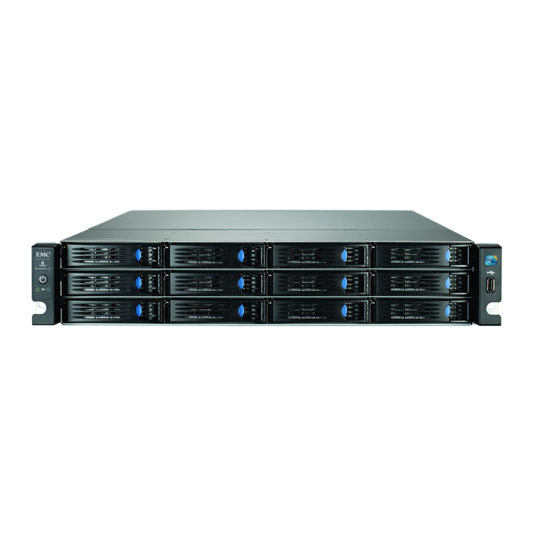
CDA 7 (front view)
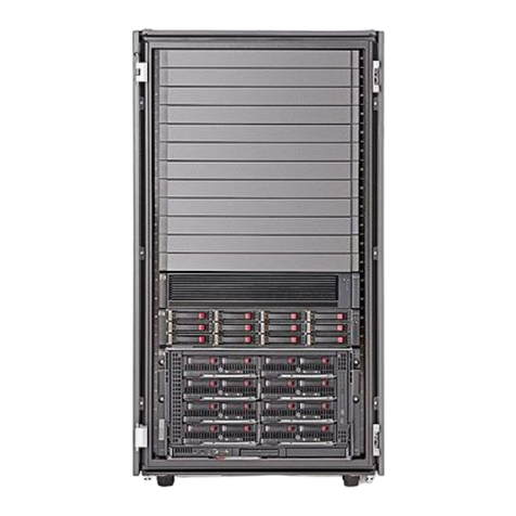
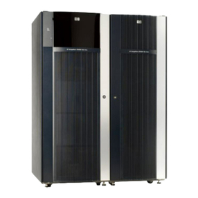
Figure 1-1 provides a front view of the exterior of the CDA 7.
Figure 1-1. CDA 7 Subsystem

CDA 7 Maintenance Manual
1-2 77 A7 48UU Rev03
CDA 7 (rear view) - 9 GB
Figure 1-2 provides a rear view of the exterior of the CDA 7 (9 GB).
A
C
I
N
E
P
O
II
00
Figure 1-2. CDA 7 (Rear View - 9 GB)

Introduction
77 A7 48UU Rev03 1-3
CDA 7 (rear view) - 18 GB and 36 GB
Figure 1-3 provides a rear view of the exterior of the CDA 7 (18 GB and 36 GB).
EPO
AC IN
II
00
Figure 1-3. CDA 7 (Rear View - 18 GB and 36 GB)

CDA 7 Maintenance Manual
1-4 77 A7 48UU Rev03
CDA 7 Main Components
Figure 1-4 shows the location of the main components in the CDA 7 chassis.
SERVICE
PROCESSOR
BATTERY
SUBSYSTE
M
ADAPTER
CARDS
REAR
DIRECTOR AND
CACHE CARDS
FRONT
DISK
DEVICES
POWER
SUBSYSTEM
INTERNAL
ETHERNET
HUB
FAN
ASSEMBLIES
Open Position
Closed
Position
Figure 1-4. CDA 7 Main Components (Exploded View)
This manual suits for next models
2
Table of contents