Bungard NE-CUT User manual

page 1 / 6
Application
NE-CUT is suitable for boards up to a width
of 530 mm. The maximum thickness of the
board depends on the material ou want to
cut. You can cut FR4 up to 3 mm, aluminium
depending on the allo up to 2 mm and
sheet steel depending on the allo up to 1.0
mm.
The cut has to be done in one stroke b a
normal strong man. A mechanical or electric-
al aid like a lever or a motor is not allowed.
This might damage the board cutter irrepar-
able.
The thinnest material ou can cut is 0,1 mm
(new board cutter or just sharpened blades
assumed). This enables the cutter even to
cut film material, clichés etc..
Features:
•Cutting width max. 530 mm
•Two knifes made of hardened and
ground steel
•Spring loaded built-in clamping unit in
the front
•Transparent cover hood for user safet
and visual control
•Metric edge scales in the front
•Full adjustable back stop with metric
scale for batch work (0...300 mm)
•Smallest cutting size (front) 45 mm
•Durable full steel construction
•All important parts angular adjustable
•Simple exchange of blades
•Adjustable cutting angle
•Adjustable clearance
Technical Datas
•Dimension (W x H x D):
74 cm x 29 cm x 45 cm
•Weight::
66 kg
Security
All dangerous parts are covered as far as
technicall possible and reasonable. The
gap between table and downholder is onl 5
mm, so it is almost impossible to get our
hand into the blade while the downholder is
mounted.
The onl source of danger is behind the ma-
chine. Never pull the lever while ou or an -
bod else is working behind the machine.
Especiall when somebod is tr ing to re-
move the cut boards from behind the ma-
chine.
Alwa s were cut proof gloves when handling
the blades. Secure the loose blades from
being touched or from falling down.
NE-CUT
Board Cutter
Instructions for use
Bungard Elektronik GmbH & Co. KG, Rilkestraße 1, 51570 Windeck – German
Tel.: +49 (0) 2292/5036, Fax: +49 (0) 2292/6175, E-mail: s[email protected]

page 2 / 6
Set Up
Important: Receiving the machine please im-
mediatel check for an transport damage. If
ou notice an transport damage please in-
form us and the carrier.
For transport reasons some parts of the Ne-
Cut are disassembled: the rear counter bar,
the belonging slide beam with scale, the
lever and the hood.
First take out the filling material and then the
disassembled parts. Bring the latter to the
place where ou want to operate the ma-
chine.
Remove the transport screws!!
Because of its heav weight carr the Ne-
Cut onl with two persons. Hold on one hand
to the table and the other under the ground
plate. The Operation place should be solid,
even and not slipper . The room should
have a non-corrosive atmosphere. A good
access to the rear is important to assemble
the counter bar and later on it will enable
ou to remove the cut boards easil .
Make sure to have enough light in the room.
If necessar install a separate light source
next to the machine in order to have a clear
sight over the cutting area.
Mount now the add-on-parts. All ou need is
a set of Allen ke s and a set of jaw
wrenches.
Stick the lever into the opening on the right
side of the eccentric axis, the chamfer point-
ing to the right. Tighten the lever with the
headless Allen ke screw (see picture1).
When ou look from the rear to the upper
blade beam ou see two loosel mounted Al-
len ke screws (see picture 2).
Unscrew them and adjust here horizontall
the flange of the slide beam. Tighten the
screws hand tight.
Set the counter-bar to a deliberate position.
Turn the lever up and back to its home posi-
tion. Take a wide board and scoop it first
against the front counter bar and then
against the rear counter bare.
NE-CUT
Board Cutter
Instructions for use
Bungard Elektronik GmbH & Co. KG, Rilkestraße 1, 51570 Windeck – German
Tel.: +49 (0) 2292/5036, Fax: +49 (0) 2292/6175, E-mail: s[email protected]
(1)
(2)

page 3 / 6
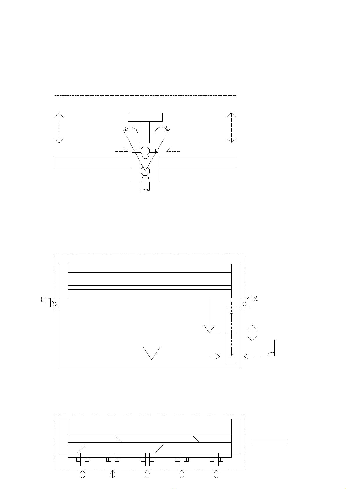
Pull the lever until the downholder fixes the
board. In this position ou can adjust the
height of the rear counter bar until it lies
smooth against the board. Now tighten the
Allen ke screws.
The parallelit of the rear counter bare was
preadjusted and proved before the machine
left the compan . However it happens some-
times that the rear counter bare does not fit
after disassembl . The reason for this could
be a an unevenness of the finishing coat. If
ou happen to notice a disparallelit after
some test cuts please read chapter adjust-
ment how to scale the counter bare again.
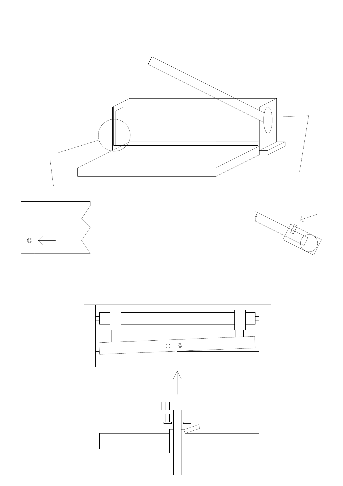
At last mount the hood and tighten it with
four screws. The two notches of the hood
belong to the rear side.
Operation
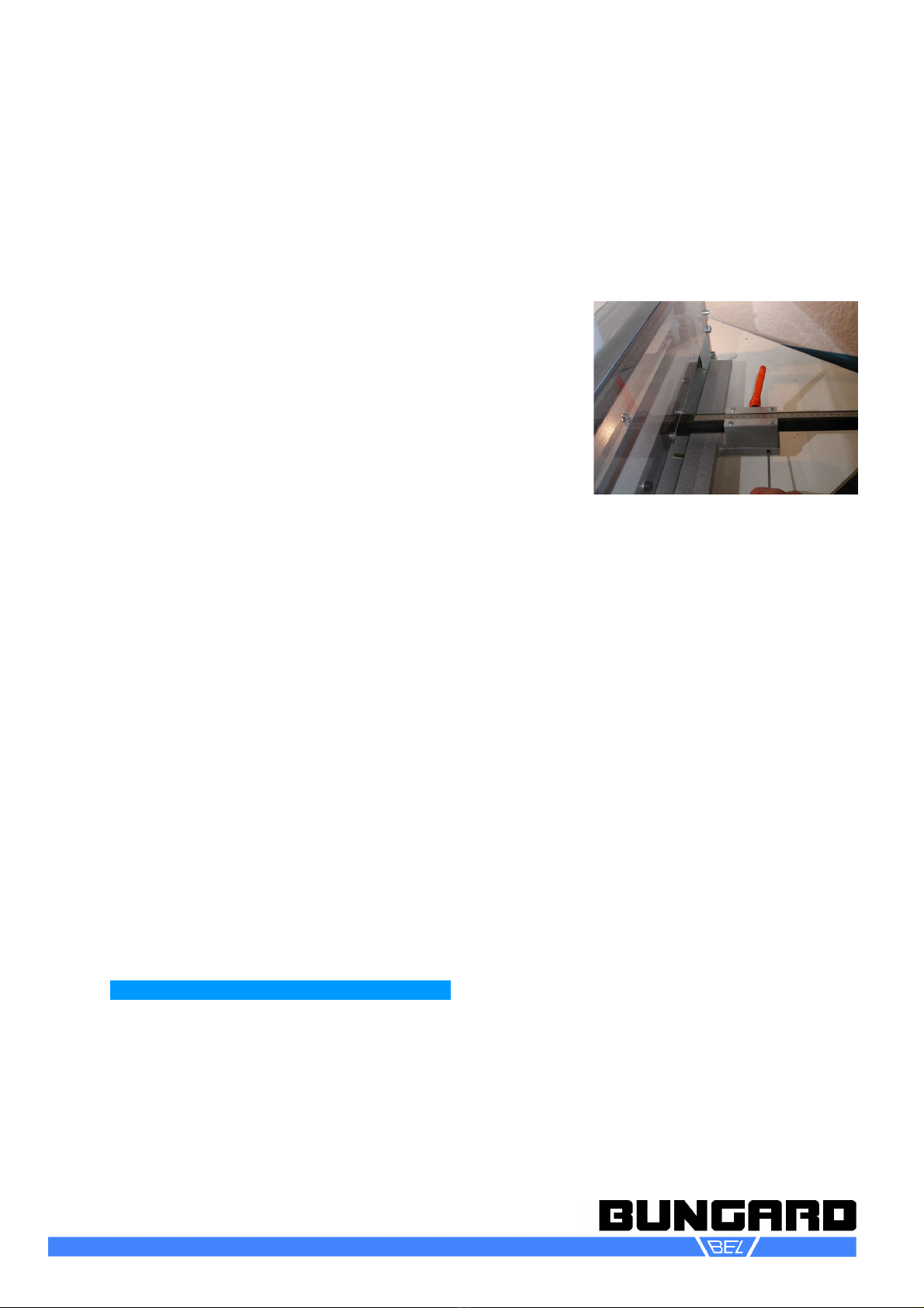
Adjust the size of the board to be cut with
the rear counter bare: Loosen the orange
knob b lifting and turning. Slide the counter
bare to the rough dimension of the board,
tighten the knob a little bit and adjust the
zero position mark precisel b knocking
against the skid of the counter bare. Then
tight the knob firml . Place the board against
the front counter bare and push it against
the rear counter bare.
Pull the lever to the front and down. The
downholder will clamp the board and then
the blade will cut it. Pull the lever all the wa
back, so the downholder releases the board.
If ou place the board precisel to the scale
of the front counter bare, ou can even per-
form some cuts without adjusting the rear
counter bare. Or ou can trim the rims of the
board b sight. If ou work without the rear
counter bare, it can happen that the board is
pushed back b the blade for about 0,1-0,2
mm. That is a general side effect of the cut-
ting procedure and no defect of the machine.
To reduce this effect we offer as an option a
front parallel counter bare.
Please make sure to take out regularl the
cuts and the oddments from the ground
plate of the machine. If the oddments are
ver small, the might stick underneath the
blade. Attention: risk of injur ! Lower the up-
per blade until the gap between upper and
lower blade is closed before ou remove
these small parts.
Disassembly
Dismount the rear counter bare onl for
transport reason because ou have to go
through the adjustment procedure again
after ou mount the counter bare . This pro-
cedure is described in the chapters Set Up
and Adjustment. The counter bare itself can
be slid off the beam after the knob is loose.
For safet reasons alwa s keep the down-
holder in its position. Nevertheless ou can
remove the downholder b pressing it down
on the side till it comes free from the press
beams which connect the downholder with
the lowering mechanism.
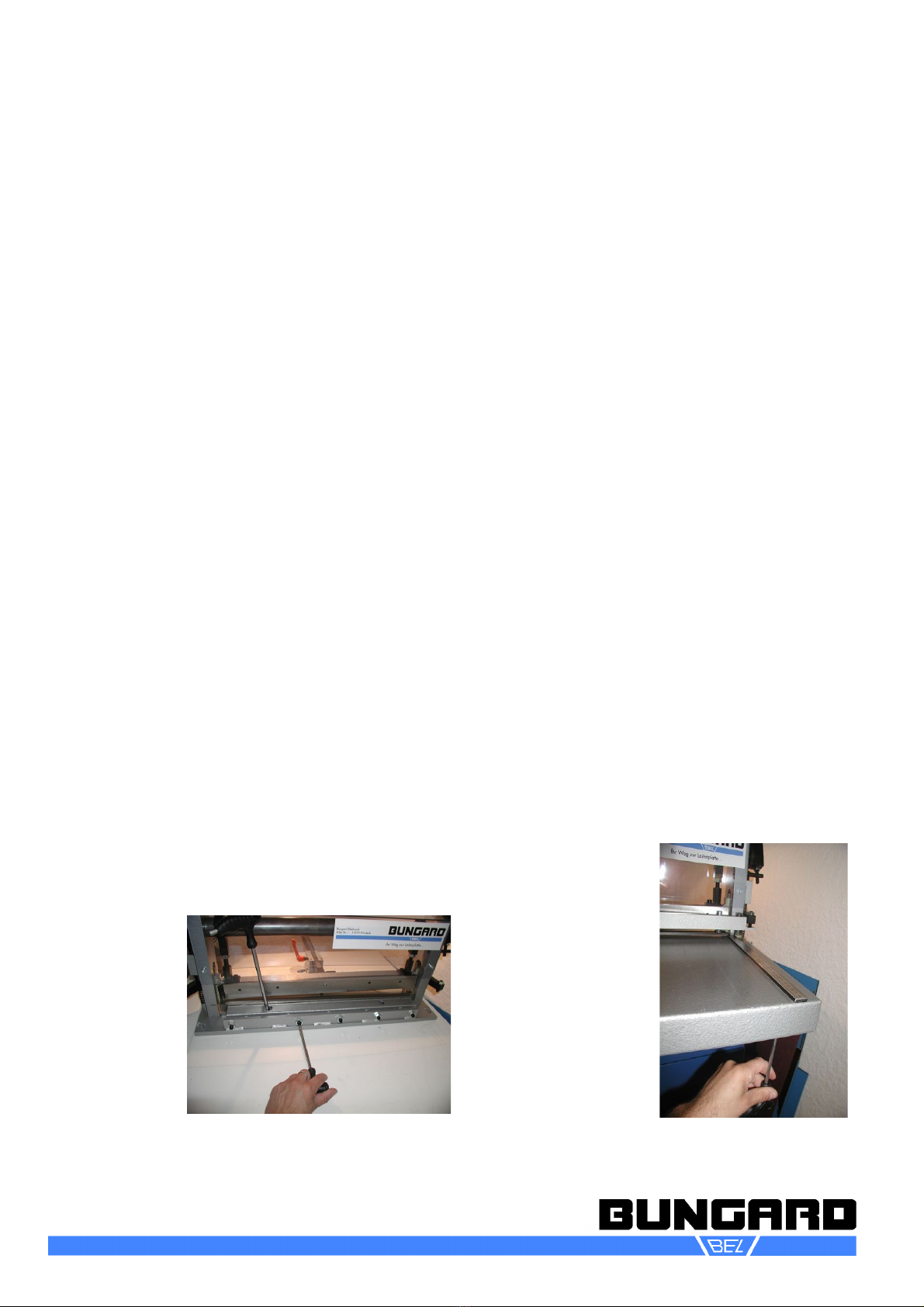
Turn awa the press beams and lift the
downholder. If ou need to have access to
the lower blade ou must remove the table.
Loosen the two screws which connect the
table to the ground plate.
NE-CUT
Board Cutter
Instructions for use
Bungard Elektronik GmbH & Co. KG, Rilkestraße 1, 51570 Windeck – German
Tel.: +49 (0) 2292/5036, Fax: +49 (0) 2292/6175, E-mail: s[email protected]

page 4 / 6
After remounting the table ouhave to con-
trol the perpendicularit of the table and if
needed readjust the scale of the front
counter bare (view chapter adjustment).
After ou removed downholder and table ou
see a square pipe which holds the lower
blade. You can reach the attachment screws
through the big top holes. Loosen the
screws and take out the square pipe with the
lower blade. If ou untight the screw coup-
ling ou can remove the lower blade.
In order to remove the upper blade just
loosen the screws of the upper blade beam.
Please pa attention to the alignment of the
blades: do not change the angles of the
blades when regrinding them and remount
the blades into the same position the were
before. After remounting the blades ou
need to readjust the gap between the two
blades (see chapter Adjustment).
Attention, danger of injur ! Alwa s were cut
proof gloves when handling the blades. Se-
cure the loose blades from being touched or
from falling down.
Under normal conditions it is not necessar
to dismount the upper blade beam, the ec-
centric axis or other parts. Nevertheless if
ou must do so for repair reasons for ex-
ample please get in touch with us.
Adjustment
Rear Counter Bare
After assembling the slide beam of the
counter bare, take a preferable broad piece
of board, push it against the rear counter
bare and cut it. Prove the parallelit of this
cut with a precise caliper gauge on the left
and on the right. If the cut is not parallel, do
the following:
Take a jaw wrench and loosen the backmost
of the two nuts underneath the counter bare.
(3)
To adjust the angle of the counter bare take
an Allen ke and turn the headless Allen ke
screws on the left and on the right of the
counter bare (see picture 3).
On the side where ou turn out the headless
screw, the size of the cut will become smal-
ler. On the side where ou turn in the screw
the gap accordingl will become bigger.
Normall ou will have to do a couple of test
cuts till both sides are exactl equal.
At last tighten the nut from underneath the
counter bare again and measure the size of
the cut. Check if the zero position mark fits
to the size of the cut. If not, loosen the
screws of the metal plate and shift the zero
position to its proper place.
Upper Blade
The upper blade is connected with screws to
the blade beam. The onl possible adjust-
ment is the angle from left to right. This
angles influences the power of the cut. The
cutting goes easier when the angle is as
aslope as possible. We preadjust the angle
this wa and ou should avoid to change this
since it influences the maximum thickness
and width of the board to be cut as well as
the shear forces attacking the boards (dis-
tortion).
NE-CUT
Board Cutter
Instructions for use
Bungard Elektronik GmbH & Co. KG, Rilkestraße 1, 51570 Windeck – German
Tel.: +49 (0) 2292/5036, Fax: +49 (0) 2292/6175, E-mail: s[email protected]

page 5 / 6
Change the angle b first loosening the
counter nut and then turn the hexagon bolt
between eccentric axis and blade holder.
Lower Blade
To disassemble the table and lower blade
read chapter Disassembl . The lower blade
is closel connected to its holder. To change
the gap between upper and lower blade ou
can move the holder of the lower blade
along the ground plate.
To do so use the 5 headless screws which
ou find between the steel bracket welded to
the ground plate and the holder. First mount
the upper blade and lower it down as far as
possible.
For the now coming adjustment ou need a
distance template. You can take foil with a
defined thickness of 0.1 mm or take two
sheets of normal paper. You calculate for
metals a gap of 1/10 of the materials thick-
ness. For pcb sheets ou can reduce the
gap.
(4)
Tighten the attachment screws of the holder
just slightl and move the holder with the
lower blade evenl against the template that
lies before the upper blade. Tighten the at-
tachment screws hand firm. Now loosen the
counter nuts of the headless screws and
turn these screws till the touch the holder
(see picture 4).
Take the template out of the cutting gap.
Now cut small stripes of the thinnest material
ou want to cut (film material e.g.) all along
the blade from the left to the right. At places
where the material was not cut but onl
bend, turn in the nearest headless screw for
some degrees and repeat the cut.
Repeat this action until our sheet was
nicel cut all along the blade. Do not turn the
headless screws too far, thus ou ma dam-
age the blades. If the screws happen to be
too far in, ou have to loosen all screws and
start the procedure once again. When ou
are done do not forget to tighten the attach-
ment screws.
Front S ale
This adjustment is alwa s necessar when
the table was disassembled (change of
blades). To assure a perpendicular cut walk
through the following steps:
Check if the screws between table and
ground plate are tightened.
(5)
Pull the ma-
chine over the
edge of the
table until ou
can reach the
frontmost at-
tachment screw
of the
ruler. Loosen
this screw care-
full (see pic-
ture 5). Take a
perpendicular
test board,
push it against
NE-CUT
Board Cutter
Instructions for use
Bungard Elektronik GmbH & Co. KG, Rilkestraße 1, 51570 Windeck – German
Tel.: +49 (0) 2292/5036, Fax: +49 (0) 2292/6175, E-mail: s[email protected]

page 6 / 6
the upper blade and knock with a small
plastic hammer against the ruler till the hole
side of the ruler touches the board.
Tighten the attachment screw and make a
test cut. Check the angle again. If ou notice
that the scale of the ruler does not fit an -
more ou will have to move the table itself.
Or ou can loose the other attachment
screw of the ruler as well and move the
ruler.
Maintenance
After use clean the machine from dust and
swarfs b vacuuming especiall the blades
and behind the blades. Do not use com-
pressed air to clean the machine from FR4
dust because then the fibre glass fibres are
dispensed all over the room.
You can clean the hood with a smooth cloth
and some non abrasive cleaner.
Clean and grease regularl all moveable
parts, especiall slides of the upper blade
run and the rings around the eccentric axis.
Depending on the amount of cuts and the
material to be cut, the blades need to be ex-
changed or resharpened. We offer blades as
spare part so ou can keep a blade-set in
reserve.
Guarantee
All machines are submitted before distribution
to examination on function and continuous op-
eration firmness. On the machine we grant a
work warrant of 12 months to our customers
starting from purchase date on accurac in
material and processing. We warrant at our
choice b exchange of incorrect parts or b re-
pair of the machine in our house. Old parts
change into our possession.
Disclaimer of Warranty
All parts subjected to wear are excluded from
this warrant . Non-observance of this manual
shall void all warrant claims.
We cannot accept subsequent claims from
damage or destruction of workpieces worked
on in the machine, because we have no know-
ledge or control over the operating conditions
at our site. This is valid in a general manner
also for requirements from damage to articles,
buildings and persons as well as the environ-
ment.
We do not warrant that the function of the ma-
chine will meet the customer's requirements or
that the operation of the machine will to this re-
gard be error free.
In no event will we be liable to the customer for
an incidental, consequential, or indirect dam-
ages of an kind, including loss of profit and
prosecution for environmental pollution, even if
we could have been aware of the possibilit of
such damages.
All information was arranged with great care.
We reserve ourselves however mistake and
technical changes without previous announce-
ment.
We explicitl exclude an warrant for dam-
ages resulting from running the machine in in
corroding, humid, dust , extremel hot or ex-
plosive atmosphere.
opyright
(C) 2008 Bungard Elektronik
NE-CUT
Board Cutter
Instructions for use
Bungard Elektronik GmbH & Co. KG, Rilkestraße 1, 51570 Windeck – German
Tel.: +49 (0) 2292/5036, Fax: +49 (0) 2292/6175, E-mail: s[email protected]

a=b+/-0.1mm
NE-CUT Einstellung / Adjustment
Tisch
Table
a
Oben
d=0.1mm
Top
b

NE-CUT: Montage / Set-Up
4x
3,
1.
Cover
Haube
Hinterer Anschlag
Counter-Bar
Rear
Hinten
Hebel
Lever
2.
Other manuals for NE-CUT
1
Other Bungard Cutter manuals