Bungard NE-CUT User manual

ne-cut-manual-e Page 1 / 10
Board Cutter NE-CUT
Translation of the Original Instruc-
tions
➔Read before use
➔Pay heed to all safety regulations
➔Keep at a safe place to refer to in the future
Table of Content
escription........................................................2
Features............................................................2
Technical ata..................................................2
Possible Options...........................................3
EG- eclaration of Conformity...........................4
Intended Use....................................................5
Safety Regulations...........................................5
Generally......................................................5
Transport......................................................5
Operation site...............................................5
Operating......................................................5
Set Up..............................................................6
Take over from the transport agent..............6
Transport to operation site............................6
Operation Site...............................................6
Mounting.......................................................6
Operating.........................................................7
isassembly.....................................................7
Adjustment.......................................................8
Upper Blade..................................................8
Lower Blade..................................................8
Front Scale...................................................9
Rear Back Stop............................................9
Cleaning and Maintenance.............................10
isposal.........................................................10
Spare part list.................................................10
Guarantee......................................................11
isclaimer of Warranty...................................11
Copyright........................................................11
Bungard Elektronik GmbH & Co. KG, Rilkestraße 1, 51570 Windeck – Germany
Tel.: +49 2292 / 9 28 28-0, Fax: +49 2292 / 9 28 28-29, E-mail: [email protected]e

ne-cut-manual-e Page 2 / 10
Description
NE-CUT is designed to cut FR4 PCB boards up to 3.0 mm or aluminium up to 2 mm thickness. epending
on customer application cutting of steel (depending on the alloy up 0.8 mm) and plastic (up to 5 mm) is
also possible same as paper or film material.
The transparent hood allows to cut single sheets by eye sight.
Features
•Cutting width max. 530 mm
•Two knifes made of hardened and ground steel
•Spring loaded built-in clamping unit in the front
•front side stop with metric scale (0.1 mm tolerance repeatability)
•Fully adjustable back stop with metric scale for batch work (0.1 mm tolerance repeatability)
•Adjustment range of back stop 0 - 300 mm
•Smallest cutting size (front) 45 mm
•urable full steel construction
•All angular and dimension determining parts adjustable
•Simple exchange of blades
•Adjustable cutting angle
•Adjustable clearance
Technical Data
Dimensions (L x H x D): 74 cm x 29 cm x 45 cm
Weight: 66 kg
Cutting Length: max. 530 mm
Adjustment range of back stop: 0 - 300 mm
Smallest cutting size (front) 45 mm
max. Board Thickness FR4 3.0 mm
max. Board Thickness Aluminium 2.0 mm
max. Board Thickness Plastic 5.0 mm
max. Board Thickness Steel 0.8 mm
Annotation: the board cutter is preset for board thickness up to 3.0 mm. If you need to cut thicker material
you need to adjust the upper blade and the clamping unit.
Technical changes reserved
Possible Options
parallel front stop (similar to picture 1)
Bungard Elektronik GmbH & Co. KG, Rilkestraße 1, 51570 Windeck – Germany
Tel.: +49 2292 / 9 28 28-0, Fax: +49 2292 / 9 28 28-29, E-mail: s[email protected]
Picture 1

ne-cut-manual-e Page 3 / 10
EG-Declaration of Conformity
E -Konformitätserklärung/Declaration of Conformity
Hersteller / Supplier: Bungard Elektronik GmbH & Co. KG
Rilkestraße 1
51570 Windeck Germany
Bevollmächtigte Person für die Zusammenstel-
lung der technischen Unterlagen:
Person in charge
Jürgen Bungard, Geschäftsführer /general director
Rilkestraße 1
51570 Windeck Germany
Product: Plattenschere / Board Cutter Ne-Cut
Hiermit erklären wir, dass die oben beschriebenen Maschinen allen einschlägigen Bestimmungen der
Maschinenrichtlinie 2006/42/EG entspricht.
ie oben genannte Maschine erfüllt die Anforderungen der nachfolgend genannten Richtlinien und Nor-
men:
We hereby declare that the machines described above complies with all relevant provisions of the Ma-
chinery irective 2006/42/EC.
The above machine meets the requirements of the following guidelines and standards:
Maschinenrichtlinie 2006/42/E / Machinery Directive 2006/42/EC
DIN EN 60204-1 Sicherheit von Maschinen - Elektrische Ausrüstung von Maschinen - Teil 1: Allge-
meine Anforderungen / Safety of machinery - Electrical equipment of machines - Part 1: General re-
quirements
DIN EN ISO 14121-1 Sicherheit von Maschinen - Risikobeurteilung - Teil 1: Leitsätze / Safety of ma-
chinery - Risk assessment - Part 1: Principles
DIN EN ISO 12100-1 Sicherheit von Maschinen - Allgemeine Gestaltungsleitsätze, Risikobeurteilung
und Risikominderung / Safety of machinery - Basic concepts, risk assessment and risk reduction
Maschinenrichtlinie / Machinery Directive 2006/42/E /37/E
Windeck, 10.02.16
Jürgen Bungard Geschäftsführer
Bungard Elektronik GmbH & Co. KG, Rilkestraße 1, 51570 Windeck – Germany
Tel.: +49 2292 / 9 28 28-0, Fax: +49 2292 / 9 28 28-29, E-mail: s[email protected]

ne-cut-manual-e Page 4 / 10
Intended Use
NE-CUT is specially designed to cut FR4 PCB boards up to 3.0 mm or aluminium up to 2 mm thickness.
epending on customer application cutting of steel (depending on the alloy up 0.8 mm) and plastic (up to
5 mm) is also possible same as paper or film material. The board cutter is preset for board thickness up to
3.0 mm. If you need to cut thicker material you need to adjust the upper blade and the clamping unit.
All other applications require our written consent, or happen at your own risk and peril.
Safety Regulations
enerally
Please read the following text carefully and pay particular attention to information on safety and commis -
sioning.
Keep this folder at a safe place. It contains information which is also for later maintenance and cleaning of
importance.
The machines are not designed to be embedded or interconnection with other machines or systems. They
may only be used in specially equipped rooms and be operated by qualified personnel. Keep away chil -
dren and pets!
Transport
Only use suitable lifting and transport equipment such as forklifts or pallet trucks . Secure the machine
against sliding / tilting
Operation site
The site should be level, site- and slip-resistant. Unrestricted access to the rear of the machine is required
for the installation of add-on parts ; later on it enables you to easily remove the cuttings .
Operating
All dangerous parts are covered as far as technically possible and reasonable. The gap between
table and clamping device is only 5 mm, so it is almost impossible to get your hand into the blade
while the clamping device is mounted.
The only source of danger is behind the machine. Never pull the lever while you or anybody else is
working behind the machine. Especially when somebody is trying to remove the cut boards from be-
hind the machine.
Always were cut proof gloves when handling the blades. Secure the loose blades from being touched
or from falling down.
For very small sections, it may happen that they stick under the knife. Caution, risk of injury! Lower the up-
per knife till the cutting gap is closed before putting your hands into the cutting area.
Bungard Elektronik GmbH & Co. KG, Rilkestraße 1, 51570 Windeck – Germany
Tel.: +49 2292 / 9 28 28-0, Fax: +49 2292 / 9 28 28-29, E-mail: [email protected]e

ne-cut-manual-e Page 5 / 10
Set Up
Take over from the transport agent
After receiving and unpacking check the machine for possible transport damages. In case of transport
damage, please inform your insurance, the transport company and the manufacturer / supplier.
Transport to operation site
Only use suitable lifting and transport equipment such as fork-
lifts or pallet trucks . Secure the machine against sliding / tilting
First take out the filling material and then the disassembled
parts. Bring the latter to the place where you want to operate
the machine.
Remove the transport screws (picture 2)!!
Because of its heavy weight carry the Ne-Cut only with two per-
sons. Hold on one hand to the table and the other under the
ground plate.
For transport reasons some parts of the Ne-Cut are disas-
sembled:
1. back stop with metric scale
2. the lever
Operation Site
The Operation place should be solid, even and not slippery. The
room should have a non-corrosive atmosphere. A good access to
the rear is important to assemble the counter bar and later on it will
enable you to remove the cut boards easily.
Make sure to have enough light in the room. If necessary install a
separate light source next to the machine in order to have a clear
sight over the cutting area.
Mounting
Mount now the add-on-parts. All you need is a set of Allen keys and
a set of jaw wrenches.
1. Lever (picture 3): Stick the lever into the opening on the
right side of the eccentric axis, the chamfer pointing to the
right. Tighten the lever with the headless Allen key screw.
2. back stop with metric scale (picture 4): When you look
from the rear to the upper blade beam you see two
loosely mounted Allen key screws. Unscrew them and ad-
just here horizontally the flange of the slide beam. Tighten
the screws hand tight.
Set the counter-bar to a deliberate position. Loosen the
red lever (you can change position of the knob by lifting
and turning).
Bungard Elektronik GmbH & Co. KG, Rilkestraße 1, 51570 Windeck – Germany
Tel.: +49 2292 / 9 28 28-0, Fax: +49 2292 / 9 28 28-29, E-mail: s[email protected]
Picture 4
Picture 2
Picture 3

ne-cut-manual-e Page 6 / 10
Turn the lever up and back to its home position. Take a wide board and scoop it first against the front side
counter bar and then against the rear counter bare.
Pull the lever until the clamping unit fixes the board. In this position you can adjust the height of the rear
counter bar until it lies smooth against the board. Now tighten the Allen key screws.
The parallelity of the rear counter bare was pre-adjusted and proved before the machine left the company.
However it happens sometimes that the rear counter bare does not fit after disassembly. The reason for
this could be a an unevenness of the finishing coat. If you happen to notice a disparallelity after some test
cuts, please read chapter adjustment how to scale the counter bare again.
Operating
Adjust the size of the board to be cut with the rear counter bare: Loosen the orange knob by lifting and
turning. Slide the counter bare to the rough dimension of the board, tighten the knob a little bit and adjust
the zero position mark precisely by knocking against the skid of the counter bare. Then tight the knob
firmly. Place the board against the front counter bare and push it against the rear counter bare.
Pull the lever to the front and down. The downholder (clamping unit) will clamp the board and then the
blade will cut it. Pull the lever all the way back, so the clamping unit releases the board.
If you place the board precisely to the scale of the front counter bare, you can even perform some cuts
without adjusting the rear counter bare. Or you can trim the rims of the board by sight. If you work without
the rear counter bare, it can happen that the board is pushed back by the blade for about 0,1-0,2 mm.
That is a general side effect of the cutting procedure and no defect of the machine. To reduce this effect
we offer as an option a front parallel counter bare.
Please make sure to take out regularly the cuts and the oddments from the ground plate of the machine. If
the oddments are very small, they might stick underneath the blade. Attention: risk of injury! Lower the
upper blade until the gap between upper and lower blade is closed before you remove these small parts.
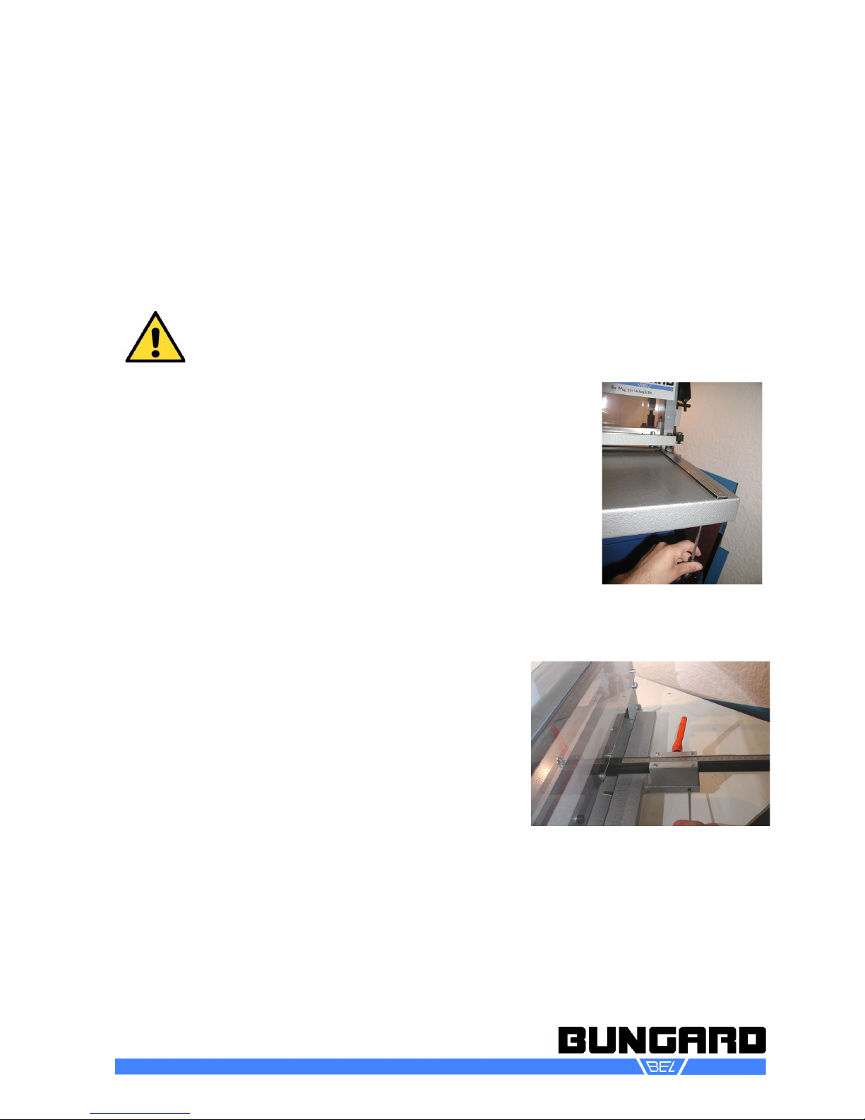
Disassem ly
ismount the rear counter bar only for transport reason, because
you have to go through the adjustment procedure again after you
mount the counter bare . This procedure is described in the chapters
Set Up and Adjustment. The counter bare itself can be slid off the
beam after the knob is loose.
For safety reasons always keep the clamping unit in its position.
Nevertheless you can remove the clamping unit by pressing it down
on the side till it comes free from the press beams which connect the
clamping unit with the lowering mechanism.
Turn away the press beams and lift the clamping unit.
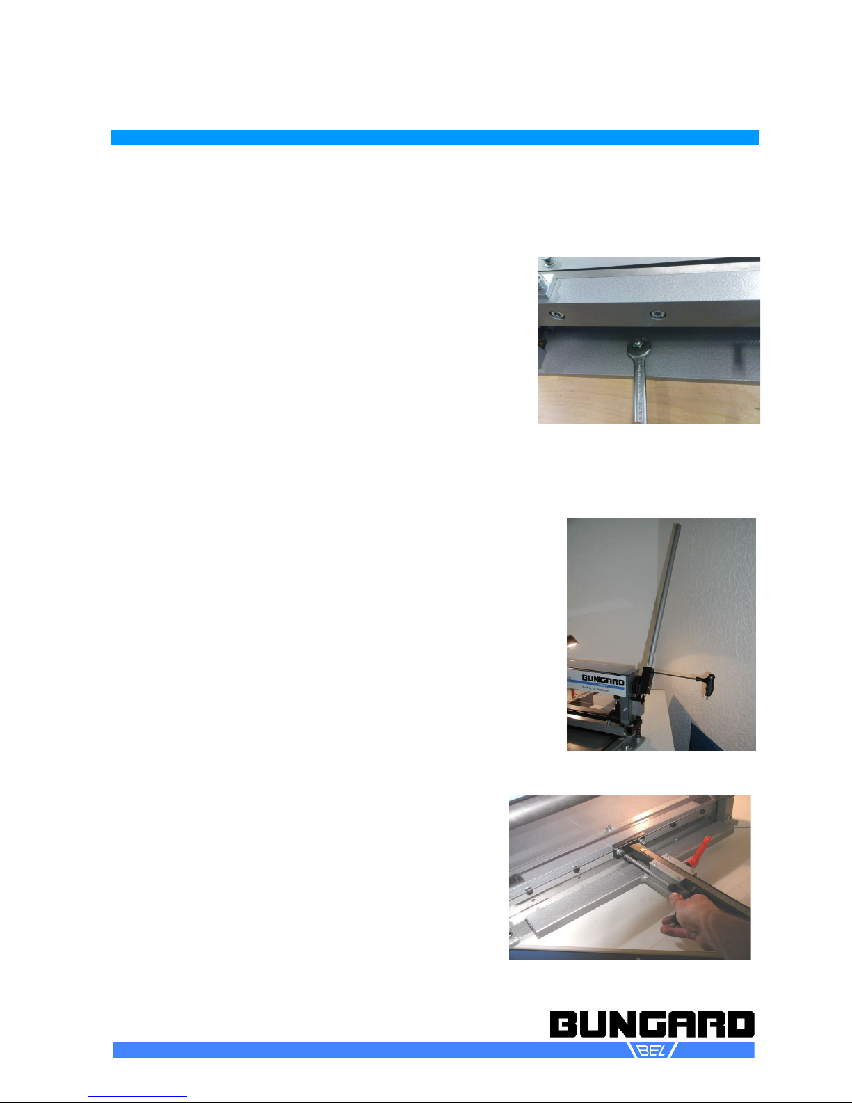
If you need to have access to the lower blade you must remove the
machine table. Loosen the two screws which connect the table to the
ground plate (Picture 5). After remounting the table you have to con-
trol the perpendicularity of the table and if needed, readjust the scale
of the front counter bare (see chapter adjustment).
Bungard Elektronik GmbH & Co. KG, Rilkestraße 1, 51570 Windeck – Germany
Tel.: +49 2292 / 9 28 28-0, Fax: +49 2292 / 9 28 28-29, E-mail: s[email protected]
Picture 5

ne-cut-manual-e Page 7 / 10
After you removed clamping unit and table you see a square pipe
which holds the lower blade (Picture 6). You can reach the attach-
ment screws through the big top holes. Loosen the screws and take
out the square pipe with the lower blade. If you unfasten the screw
coupling you can remove the lower blade.
In order to remove the upper blade just loosen the screws of the up-
per blade beam.
Please pay attention to the alignment of the blades: do not change
the angles of the blades when regrinding them and remount the
blades into the same position they were before. After remounting the
blades you need to readjust the gap between the two blades (see
chapter Adjustment).
Attention, danger of injury! Always were cut proof gloves when hand-
ling the blades. Secure the loose blades from being touched or from falling down.
Under normal conditions it is not necessary to dismount the upper blade beam, the eccentric axis or other
parts. Nevertheless if you must do so for repair reasons for example please get in touch with us.
Adjustment
Upper Blade
The upper blade is connected with screws to the blade beam. The only possible
adjustment is the angle from left to right. This angles influences the power of the
cut. The cutting goes easier when the angle is as aslope as possible. We pre-ad-
just the angle this way and you should avoid to change this since it influences the
maximum thickness and width of the board to be cut as well as the shear forces
attacking the boards (distortion).
Change the angle by first loosening the counter nut and then turn the
hexagon bolt between eccentric axis and blade holder (Picture 7).
Lower Blade
To disassemble the table and lower blade read chapter Dis-
assembly. The lower blade is closely connected to its hold-
er. To change the gap between upper and lower blade you
can move the holder of the lower blade along the ground
plate.
To do so use the 5 headless screws which you find between
the steel bracket welded to the ground plate and the holder
(Picture 8). First mount the upper blade and lower it down
as far as possible.
For the now coming adjustment you need a distance tem-
plate. You can take foil with a defined thickness of 0.1 mm
or take two sheets of normal paper. You calculate for metals
a gap of 1/10 of the materials thickness. For pcb sheets you
can reduce the gap.
Bungard Elektronik GmbH & Co. KG, Rilkestraße 1, 51570 Windeck – Germany
Tel.: +49 2292 / 9 28 28-0, Fax: +49 2292 / 9 28 28-29, E-mail: [email protected]e
Picture 6
Picture 8
Picture 7

ne-cut-manual-e Page 8 / 10
Tighten the attachment screws of the holder just slightly and move the holder with the lower blade
evenly against the template that lies before the upper blade. Tighten the attachment screws hand
firm. Now loosen the counter nuts of the headless screws and turn these screws till they touch the
holder.
Take the template out of the cutting gap.
Now cut small stripes of the thinnest material you want to cut (film material e.g.) all along the blade
from the left to the right. At places where the material was not cut but only bend, turn in the nearest
headless screw for some degrees and repeat the cut.
Repeat this action until your sheet was nicely cut all along the blade.
o not turn the headless screws too far, thus you may damage the blades. If the
screws happen to be too far in, you have to loosen all screws and start the procedure
once again. When you are done do not forget to tighten the attachment screws!
Front Scale
This adjustment is always necessary when the table was disassembled
(change of blades). To assure a perpendicular cut walk through the fol-
lowing steps:
Check if the screws between table and ground plate are tightened. Pull
the machine over the edge of the table until you can reach the front
most attachment screw of the ruler. Loosen this screw carefully (see
picture 9). Take a perpendicular test board, push it against the upper
blade and knock with a small plastic hammer against the ruler till the
hole side of the ruler touches the board.
Tighten the attachment screw and make a test cut. Check the angle
again. If you notice that the scale of the ruler does not fit anymore you
will have to move the table itself. Or you can loose the other attachment
screw of the ruler as well and move the ruler.
Rear Back Stop
After assembling the slide beam of the counter bare, take a
preferable broad piece of board, push it against the rear
counter bare and cut it. Prove the parallelity of this cut with a
precise caliper gauge on the left and on the right. If the cut is
not parallel, do the following:
Take a jaw wrench and loosen the backmost of the two nuts
underneath the counter bare.
To adjust the angle of the counter bare take an Allen key and
turn the headless Allen key screws on the left and on the
right of the counter bare (see picture 3).
On the side where you turn out the headless screw, the size
of the cut will become smaller. On the side where you turn in the screw the gap accordingly will become
igger. Normally you will have to do a couple of test cuts till both sides are exactly equal.
At last tighten the nut from underneath the counter bare again and measure the size of the cut. Check if
the zero position mark fits to the size of the cut. If not, loosen the screws of the metal plate and shift the
zero position to its proper place.
Bungard Elektronik GmbH & Co. KG, Rilkestraße 1, 51570 Windeck – Germany
Tel.: +49 2292 / 9 28 28-0, Fax: +49 2292 / 9 28 28-29, E-mail: s[email protected]
Picture 10
Picture 9

ne-cut-manual-e Page 9 / 10
Cleaning and Maintenance
After use clean the machine from dust and chips by vacuuming especially the blades and behind the
blades. o not use compressed air to clean the machine from FR4 dust because then the fibre glass
fibres are dispensed all over the room.
You can clean the hood with a smooth cloth and some non abrasive cleaner.
Clean and grease regularly all moveable parts, especially slides of the upper blade run and the rings
around the eccentric axis. epending on the amount of cuts and the material to be cut, the blades need to
be exchanged or resharpened. We offer blades as spare part so you can keep a blade-set in reserve.
Disposal
The board cutter Ne-Cut is made from recyclable materials and is to be supplied at a later decomissioning
in a proper and environmentally friendly manner.
Spare part list
Bungard Elektronik GmbH & Co. KG, Rilkestraße 1, 51570 Windeck – Germany
Tel.: +49 2292 / 9 28 28-0, Fax: +49 2292 / 9 28 28-29, E-mail: s[email protected]
Name
630004 Exzenterwelle
630008 Sechskant mit Kugelkopf
630001 Satz Messer
630006 Bolzen mit Schlitz
630007 Scheibe
630005
630002 Haube
Artikelnr. English
eccentric roller
Hexagon with Ball Head
set of blades
Bolts with slot
disc
Exzenterscheibe eccentric disc
Hood

ne-cut-manual-e Page 10 / 10
Guarantee
All machines are submitted before distribution to examination on function and continuous operation firm-
ness. On the machine we grant a work warranty of 12 months to our customers starting from purchase
date on accuracy in material and processing. We warrant at our choice by exchange of incorrect parts or
by repair of the machine in our house. Old parts change into our possession.
Disclaimer of Warranty
All parts subjected to wear (blades and movable parts) are excluded from this warranty. Non-observance
of this manual shall void all warranty claims.
We cannot accept subsequent claims from damage or destruction of workpieces worked on in the ma-
chine, because we have no knowledge or control over the operating conditions at your site. This is valid in
a general manner also for requirements from damage to articles, buildings and persons as well as the en -
vironment.
We do not warrant that the function of the machine will meet the customer's requirements or that the oper-
ation of the machine will to this regard be error free.
In no event will we be liable to the customer for any incidental, consequential, or indirect damages of any
kind, including loss of profit and prosecution for environmental pollution, even if we could have been
aware of the possibility of such damages.
All information was arranged with great care. We reserve ourselves however mistake and technical
changes without previous announcement.
We explicitly exclude any warranty for damages resulting from running the machine in in corroding, humid,
dusty, extremely hot or explosive atmosphere.
Copyright
(C) 2016 Bungard Elektronik
Bungard Elektronik GmbH & Co. KG, Rilkestraße 1, 51570 Windeck – Germany
Tel.: +49 2292 / 9 28 28-0, Fax: +49 2292 / 9 28 28-29, E-mail: [email protected]e
Other manuals for NE-CUT
1
Table of contents
Other Bungard Cutter manuals